

itaia FM-6, Photometer FM-4 Operating Manual
Operating manual
Photometer: FM-6
Litostrojska cesta 44/d, SI-1000 Ljubljana
T +386 (1) 514 18 00, F +386 (1) 514 18 04
info@itaia.si, www.itaia.si
ELECTRONICS
RESEARCH
DEVELOPMENT


Table of Contents
1. SAFETY INFORMATION AND CAUTION ........................................... 1
1. 1. GENERAL ................................................................................................ 1
1. 2. FIRE-EXTINGUISHING GEAR ............................................................. 2
1. 3. SAFETY PRECAUTIONS ....................................................................... 2
2. GUIDELINE FOR CONNECTION AND USE OF PHOTOMETER ... 4
2. 1. FIELD OF USE ........................................................................................ 4
2. 2. MOUNTING AND PLACEMENT .......................................................... 4
2. 3. CONNECTIONS ...................................................................................... 4
2. 4. ONBOARD INDICATORS ...................................................................... 6
2. 4. 1. Serial Communication Port .......................................................................... 6
2. 4. 2. Use of 230 V AC Contactor Outputs ............................................................. 7
2. 4. 3. Use of U/I/f Analog Outputs ......................................................................... 7
2. 5. CALIBRATION ....................................................................................... 8
3. PC SOFTWARE »STREET LIGHT VISION« ......................................... 9
3. 1. WRITING DATA TO THE PHOTOMETER ........................................ 10
3. 2. READING DATA FROM THE PHOTOMETER .................................. 11
3. 3. SETTING UP PC COMMUNICATION ................................................ 12
3. 4. DATA LOGGING .................................................................................. 14
4. MAINTENANCE ...................................................................................... 15
4. 1. CHECKING AND MAINTENANCE .................................................... 15
4. 2. SERVICING ........................................................................................... 15
4. 3. TROUBLESHOOTING .......................................................................... 16
4. 4. SPARE PARTS....................................................................................... 16
5. TECHNICAL DATA ................................................................................ 17
5. 2. TRANSPORT AND STOCKING .......................................................... 18
5. 3. DISPOSAL ............................................................................................. 18
6. CE DECLARATION OF CONFORMITY ............................................ 18
7. WARRANTY OBLIGATIONS ............................................................... 18

Operating manual: PHOTOMETER FM
-
6
1
1. Safety information and caution
1. 1. General
The device, connected and used in accordance with following instructions, is safe to use.
All electrical parts are protected against water, dust and dirt by the relevant IP class.
Housing prevents direct contact with any parts under voltage.
! CAUTION: For any injury resulting from improper use, the user
takes full responsibility.
!
BEFORE MOUNTING AND CONNECTING THE
DEVICE READ MANUAL CAREFULLY!
!
THE CONNECTING OF DEVICE MUST BE CARIED
OUT BY QUALIFIED PERSONNEL!
!
WHEN CONNECTING, DISCONNECT ELECTRICAL
POWER FIRST!
!
DO NOT BLOCK ACCESS TO ELECTRICAL PARTS
USED FOR EMERGENCY STOP, CLEANING AND
MAINTENANCE!
!
ALL METAL PARTS OF HOUSING MUST BE
GROUNDED!
!
MAKE SURE THAT WATER DOES NOT GET IN
TOUCH WITH PARTS UNDER VOLTAGE!
Connecting of the device must be done by qualified personnel and in accordance with
local standards. After mounting and connection control measurements must be carried
out to ensure safe and correct operation.
!

Operating manual: PHOTOMETER FM
-
6
2
1. 2. Fire-extinguishing gear
In case of fire use CO2 based fire extinguisher and other equipment following procedures
in accordance with fire-safety regulations.
1. 3. Safety precautions
Safety precautions are meant to provide personal safety and long service life of device.
Any person take part of mounting, connecting or maintenance of the device must follow
this manual and local safety regulations. They have to be qualified for the job and use
appropriate technical equipment.
Before starting:
Disconnect circuit breakers at input and output of the device and make
sure there is no voltage present.
Make sure power is disconnected during the time of mounting and
connecting.
Check the voltage presence with an instrument.
Check grounding connection.
Provide protection against touching the parts under voltage.
Qualified personnel
Transport, mounting, connecting, commissioning and maintenance of the device can
only be performed by personnel:
with job qualification and experience,
familiar with up to date safety standards and
with knowledge of basic working principles of the device.
Responsibility
We take no responsibility for proper operation and any consequences resulting from use
in discordance with this manual. Safety measures must be provided by user working with
device.
In case of malfunction, please, provide us following information:
type of the device,
serial number,
errors detected,
overall time of operation,
environmental conditions and
application information.

Operating manual: PHOTOMETER FM
-
6
3
Our Technical Support
Litostrojska cesta 44/d, SI-1000 Ljubljana
T +386 (1) 514 18 00, F +386 (1) 514 18 04
info@itaia.si, www.itaia.si
Declaration Of Conformity
The device complies with relevant European directives (CE declaration of conformity):
– Electromagnetic compatibility (ULRS, no. 132/2006)
Directive 2004/108/EC and its amendments
– Low voltage Directive (ULRS, no. 27/04)
Directive 2006/95/EC and its amendments

Operating manual: PHOTOMETER FM
-
6
4
2. Guideline for Connection and Use of Photometer
2. 1. Field of Use
Photometer is designed for measuring and regulation of traffic area illumination. Based
on L20 measurement according to CIE standard it establishes adequate illumination at
any time of day and any light conditions. Integrated logic controller and software provide
complete solution for tunnel lighting regulation with no external controller necessary.
Photometer FM-6 is provided with analogue U/I/f outputs for additional PLC or SCADA
connection. For local lighting control 6-channel 230 V AC, programmable, contactordriving outputs are available. Full function control, measuring range, output channel
switching and time averaging interval are PC programmable using software provided.
2. 2. Mounting and Placement
Photometer comes with wall/pole fixture; special pole fixture is also available (optional).
When used for tunnel entrance portal-lighting measurement, the photometer is installed
at the stopping distance before the tunnel entrance. It should be pointed directly to the
entrance. Mounting on pole, take special care for proper pole grounding, including any
foldings or joints!
When it is used to measure in-tunnel light conditions, it should be mounted at the height
of app. 4.5 metres and pointed to the spot one reach in 3 seconds at maximum allowed
speed. In this case the driver’s view cannot be simulated accuratley due to mounting
height and measuring result shlold be adopted by correction factor (usually between 1.05
and 1.20). For in-tunnel use, especially in long tunnels choose full-stainless steel
hausing option.
Once mounted, undisturbed view-field of the photometer must be provided. There should
be no light sources, either any light reflecting objects in the view-field of the photometer.
Any of those can considerably affect light measuring accuracy.
2. 3. Connections
Photometer is connected to the mains power supply 230 V AC and to the tunnel light
controlling system. All connections are done from the back side with cover removed. Cables
of 3-9 leads and minimum 0.75 mm2 must be used for 230 V AC power outputs. For
analogue U/I/f outputs and communication coaxial 2-4 lead data cables are recommended.
Maximum connection distance is up to 400 metres.
After final connection and successful commition place desiccant bag provided in the
photometer’s housing and push it towards front window. Take care it is not touching any
electrical part! Cable inlet-glands and back cover must be well tightened after final
connection!
Operating manual: PHOTOMETER FM
-
6
5
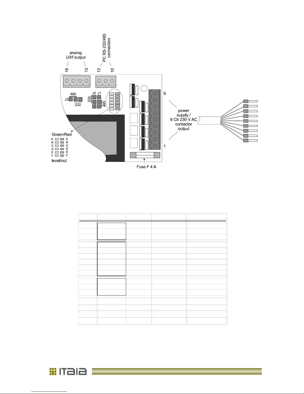
Picture 1: Connectors behind the rear cover
Table 1: Pin out and description
pin port voltage description
1 L-
power
230 V AC power
2
PWR
ground / grounding
3 N-
power
230 V AC power
4 out F 230 V AC
contactor out. F
5 out E 230 V AC
contactor out. E
6
contactor
out D 230 V AC
contactor out. D
7
out
out C 230 V AC
contactor out. C
8 out B 230 V AC
contactor out. B
9 out A 230 V AC
contactor out. A
10
PC
GND 0 V DC
programming/control
11
RS 232
RX / D+
±
12 V DC
programming/control
12
/485
TX / D-
±
12 V DC
programming/control
13
LOGIC I/O
f
port
0-15 V DC
freq./range
out
; Event
in
14
analog
GND 0 V DC
15
analog
I
out
4-20 mA current output
16
analog
U
out
0-10 V DC voltage output
Operating manual: PHOTOMETER FM
-
6
6
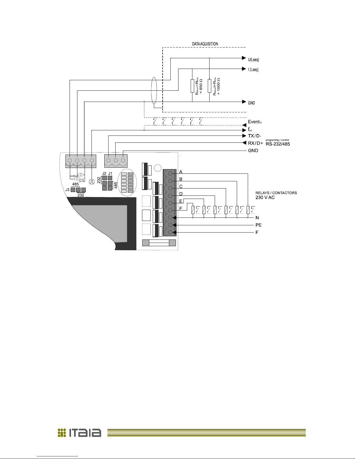
Picture 2: Photometer connection
2. 4. Onboard Indicators
From back side visible LED indicators on PCB indicate current light conditions - green and
contactor output status – red (see Picture 1). Other LEDs are status indicators and have no
meaning for the user.
2. 4. 1. Serial Communication Port
The photometer's selectable communication port can be configured for RS-232 or RS-485.
Set jumpers J1...J3 to select the protocol. Connection distance can be up to 20 m for RS232 and 300 m for RS-485. Communication supports the complete set of photometer’s
functions, setup parameters and output values.
When serial communication is used for on-line data transfer always choose RS-485. Use
RS-232 for parametric setup or laboratory use only.
 Loading...