


iC5000 & iC5700 Debug Adapters V1.6
User Manual

This document and all documents accompanying it are copyrighted by iSYSTEM AG and all
rights are reserved. Duplication of these documents is allowed for personal use. In all other
cases, written consent from iSYSTEM is required.
Copyright iSYSTEM AG.
All rights reserved.
All trademarks are property of their respective owners.
iSYSTEM is an ISO 9001 certified company.
www.isystem.com

Contents
Introduction ................................................................................................................................. 1
20-pin 2.54mm ARM Debug Adapter ........................................................................................... 2
Texas Instruments 14-pin 2.54mm Adapter ............................................................................ 3
20-pin 2.54mm Cortex Debug Adapter ......................................................................................... 4
14-pin 2.54mm ARM Debug Adapter ........................................................................................... 5
20-pin 1.27mm AMP Cortex Debug Adapter ............................................................................... 6
38-pin Mictor ARM ETM 16-bit D. Adapter .................................................................................. 7
Texas Instruments 60-pin MIPI Adapter.............................................................................. 9
10-pin 1.27mm Cortex Debug Adapter ...................................................................................... 11
10-pin 1.27mm Custom Cortex D. Adapter ................................................................................ 14
20-pin 1.27mm Cortex Debug Adapter ....................................................................................... 15
20-pin 1.27 x 2.54mm Compact TI-20 D. Adapter ...................................................................... 19
16-pin 1.27mm Custom ARM Debug Adapter ............................................................................ 21
14-pin 2.54mm MPC5xxx Debug Adapter .................................................................................. 22
ECU14 JTAG 10-pin 1.27mm Adapter ................................................................................ 24
38-pin Mictor MPC5xxx Nexus 16-bit D. Adapter ...................................................................... 26
50-pin ERF8 MPC5xxx Nexus Adapter ............................................................................... 28
50-pin ERF8 MPC5xxx Nexus 16-bit D. Adapter ......................................................................... 30
16-pin 2.54mm Infineon JTAG Debug Adapter .......................................................................... 32
10-pin 1.27mm Tricore ECU14 Debug Adapter .......................................................................... 33
10-pin 1.27mm Tricore MEDC17 Debug Adapter ...................................................................... 35
6-pin 2.54mm Infineon I2C Debug Adapter ................................................................................ 36
10-pin 1.27mm Infineon DAP2 Wide D. Adapter ....................................................................... 38
22-pin ERF8 DAP2 Debug Adapter ............................................................................................. 42
20-pin 2.54mm Renesas V850/RH850 D. Adapter ..................................................................... 44
14-pin 2.54mm Renesas RH850 Debug Adapter ......................................................................... 45
10-pin 1.27mm Renesas RH850 Debug Adapter ........................................................................ 46
38-pin Mictor RH850 Nexus 16-bit D. Adapter .......................................................................... 49

1
Introduction
The iC5000 and the iC5700 BlueBox adapt to the specific target architecture and target debug
connector through a dedicated debug adapter.
This document provides detailed information on all debug adapters which are used in
conjunction with the iC5000 and the iC5700 BlueBox, and are supported by winIDEATM 9.17.0
or newer.
Ordering Code
Description
IC50111-1
20-pin 2.54mm ARM Debug Adapter
IC50111-2
20-pin 2.54mm Cortex Debug Adapter
IC50112
14-pin 2.54mm ARM Debug Adapter
IC50113-AMP
20-pin 1.27mm AMP Cortex Debug Adapter
IC50115
38-pin Mictor ARM ETM 16-bit Debug Adapter
IC50116-2
10-pin 1.27mm Cortex Debug Adapter
IC50116-CUST2
10-pin 1.27mm Custom Cortex Debug Adapter
IC50118-2
20-pin 1.27mm Cortex Debug Adapter
IC50119
20-pin 1.27 x 2.54mm Compact TI-20 Debug Adapter
IC50120
16-pin 1.27mm Custom ARM Debug Adapter
IC50150
14-pin 2.54mm MPC5xxx Debug Adapter
IC50152
38-pin Mictor MPC5xxx Nexus 16-bit Debug Adapter
IC50152-12
38-pin Mictor MPC5xxx Nexus 16-bit Debug Adapter, 12cm length
IC50156
50-pin ERF8 MPC5xxx Nexus 16-bit Debug Adapter
IC50160
16-pin 2.54mm Infineon JTAG Debug Adapter
IC50160-ECU14
10-pin 1.27mm Tricore ECU14 Debug Adapter
IC50160-MEDC17
10-pin 1.27mm Tricore MEDC17 Debug Adapter
IC50162
6-pin 2.54mm Infineon I2C Debug Adapter
IC50163-2
10-pin 1.27mm Infineon DAP2 Wide Debug Adapter
IC50164
22-pin ERF8 DAP2 Debug Adapter
IC50171
20-pin 2.54mm V850/RH850 Debug Adapter
IC50176
14-pin 2.54mm RH850 Debug Adapter
IC50176-EPS
10-pin 1.27mm RH850 Debug Adapter
IC50177
38-pin Mictor RH850 Nexus 16-bit Debug Adapter
More information can be found on our website at www.isystem.com or simply contact
our sales team via sales@isystem.com
This symbol is used within the manual to highlight important safety notices.

2
20-pin 2.54mm ARM Debug Adapter
Ordering code
IC50111-1
This debug adapter is used to connect the iC5000 and the iC5700 BlueBox to the Cortex-A, the
Cortex-R, the ARM7 and the ARM9 based target. It’s used to connect to the embedded target
featuring a 20-pin 2.54 mm pitch target debug connector with the ARM pinout.
The debug adapter connects to the 25cm 40-pin ribbon cable coming from the BlueBox and to
the target debug connector on the other side. Refer to the BlueBox User Manual for more
details on connecting the debug adapter.
The following pinout is valid on the target side:
Signal direction
Signal
Pin
Pin
Signal
Signal direction
I
VTref
1 2 NC
O
nTRST
3 4 GND O
NC / TDI
5 6 GND
I/O / O
SWDIO / TMS
7 8 GND O
SWDCLK / TCK
9
10
GND
I
RTCK
11
12
GND I
SWO / TDO
13
14
GND
I/O
nSRST
15
16
GND O
DBGRQ
17
18
GND
I
DBACK
19
20
GND
20-pin ARM pinout
When connecting the BlueBox to the new embedded target for the first time, double
check that the debug adapter pinout matches with the target debug connector. Note
that a mismatch can result in a hardware failure.
The debug adapter features resettable fuses on all pins except for pin 11 and 19. These fuses
protect debug signals against overcurrent and cycle back to a conductive state after the
excessive current fades away.
The debug adapter connects to the target via a 20-pin 2.54 mm connector, for example
Yamaichi FAS-2001-2101-2-0BF. A target should feature a matching part, for example WÜRTH
ELEKTRONIK 61202021621.

3
Texas Instruments 14-pin 2.54mm Adapter
Embedded targets based on Texas Instruments (TI) ARM microcontroller can feature Texas
Instruments ARM 14-pin target debug connector with the TI the proprietary pinout.
An adapter connecting at the end of the 20-pin 2.54mm ARM Debug Adapter is available for
Texas Instruments ARM 14-pin pinout and must be ordered separately under the
IAPIN20ARM14TI ordering code. Make sure you don’t mix up Texas Instruments pinout with
the standard 14-pin 2.54mm ARM pinout (debug adapter IC50112).
Ordering code
IAPIN20ARM14TI
The following pinout is valid on the target side:
Signal direction
Signal
Pin
Pin
Signal
Signal direction
NC
1 2 GND
O
nTRST
3 4 GND O
TDI
5 6 GND
O
TMS
7 8 GND O
TCK
9
10
GND
I
TDO
11
12
nSRST
I/O
I
VTref
13
14
GND
14-pin TI ARM pinout
When connecting the BlueBox to the new embedded target for the first time, double
check that the adapter pinout matches with the target debug connector. Note that a
mismatch can result in a hardware failure.
A jumper is present on the adapter. If the jumper is populated, the SYSTEM RESET line is
connected to pin 14 on the target side. If SYSTEM RESET is not needed, the jumper should be
removed.
The adapter connects to the target via a 14-pin 2.54 mm connector, for example Yamaichi FAS1401-2101-2-0BF. A target should feature a matching part, for example WÜRTH ELEKTRONIK
61201421621.
This adapter can only be used in conjunction with the 20-pin 2.54mm ARM Debug
Adapter (ordering code IC50111-1).

4
20-pin 2.54mm Cortex Debug Adapter
Ordering code
IC50111-2
This debug adapter is used to connect the iC5000 and the iC5700 BlueBox to the Cortex-M
based target. It’s used to connect to the embedded target featuring a 20-pin 2.54 mm pitch
target debug connector with the ARM pinout.
The debug adapter connects to the 25cm 40-pin ribbon cable coming from the BlueBox and to
the target debug connector on the other side. Refer to the BlueBox User Manual for more
details on connecting the debug adapter.
The following pinout is valid on the target side:
Signal direction
Signal
Pin
Pin
Signal
Signal direction
I VTref
1
2
SWDIO/TMS
I/O
GND
3
4
SWCLK/TCK
O
GND
5
6
SWO/TDO
I
GND
7
8
NC/TDI
O
GND
9
10
nSRST
I/O
GND
11
12
TRCLK
I
GND
13
14
TRD0
I
GND
15
16
TRD1
I
GND
17
18
TRD2
I
I GND
19
20
TRD3
I
20-pin Cortex-M pinout
When connecting the BlueBox to the new embedded target for the first time, double
check that the debug adapter pinout matches with the target debug connector. Note
that a mismatch can result in a hardware failure.
The debug adapter features resettable fuses on pins 1, 2, 4, 6, 8 and 10. These protect debug
signals against overcurrent. These fuses cycle back to a conductive state after the excessive
current fades away.
The debug adapter connects to the target via a 20-pin 2.54 mm connector, for example
Yamaichi FAS-2001-2101-2-0BF. A target should feature a matching part, for example WÜRTH
ELEKTRONIK: 612 020 216 21.

5
14-pin 2.54mm ARM Debug Adapter
Ordering code
IC50112
This debug adapter is used to connect the iC5000 and the iC5700 BlueBox to the Cortex-A, the
Cortex-R, the ARM7 and the ARM9 based target. It’s used to connect to the embedded target
featuring a 14-pin 2.54 mm pitch target debug connector with the ARM pinout.
The debug adapter connects to the 25cm 40-pin ribbon cable coming from the BlueBox and to
the target debug connector on the other side. Refer to the BlueBox User Manual for more
details on connecting the debug adapter.
The following pinout is valid on the target side:
Signal direction
Signal
Pin
Pin
Signal
Signal direction
NC 1 2
GND
O
nTRST
3 4 GND O
TDI
5 6 GND
O
TMS
7 8 GND O
TCK
9
10
GND
I
TDO
11
12
nSRST
I/O
I
VTref
13
14
GND
14-pin ARM pinout
When connecting the BlueBox to the new embedded target for the first time, double
check that the debug adapter pinout matches with the target debug connector. Note
that a mismatch can result in a hardware failure.
The debug adapter features resettable fuses on all pins. These fuses protect debug signals
against overcurrent and cycle back to a conductive state after the excessive current fades
away.
The debug adapter connects to the target via a 14-pin 2.54 mm connector, for example
Yamaichi FAS-1401-2101-2-0BF. A target should feature a matching part, for example WÜRTH
ELEKTRONIK 61201421621.

6
20-pin 1.27mm AMP Cortex Debug Adapter
Ordering code
IC50113-AMP
This debug adapter is used to connect the iC5000 and the iC5700 BlueBox to the Cortex-M
based target. It’s used to connect to the embedded target featuring a 20-pin 1.27mm
AMPMODU target debug connector with the Cortex-M pinout.
The debug adapter connects to the 25cm 40-pin ribbon cable coming from the BlueBox and to
the target debug connector on the other side. Refer to the BlueBox User Manual for more
details on connecting the debug adapter.
The following pinout is valid on the target side:
Signal direction
Signal
Pin
Pin
Signal
Signal direction
I
VTref
1 2 SWDIO / TMS
I/O / O
GND
3 4 SWCLK / TCK
O
GND
5 6 SWO / TDO
I GND
7 8 NC / TDI
O
GND
9
10
nSRST
I/O
GND
11
12
TRCLK
I
GND
13
14
TRD0 I
GND
15
16
TRD1
I
GND
17
18
TRD2 I
GND
19
20
TRD3
I
20-pin Cortex-M pinout
Blue colored signals are parallel trace signals.
When connecting the BlueBox to the new embedded target for the first time, double
check that the debug adapter pinout matches with the target debug connector. Note
that a mismatch can result in a hardware failure.
The debug adapter features resettable fuses on pins 1, 2, 4, 6, 8 and 10. These protect debug
signals against overcurrent and cycle back to a conductive state after the excessive current
fades away. Signals on pins 12, 14, 16, 18 and 20 are protected via 100 ohm serial resistors.
The debug adapter connects to the target via a 20 -pin AMP connector, for example TE
connectivity, part number 1-111196-8. A target should feature a matching part, for example TE
connectivity part number 5-104549-2 in SMT technology.

7
38-pin Mictor ARM ETM 16-bit D. Adapter
Ordering code
IC50115
This debug adapter is used to connect the iC5000 and the iC5700 BlueBox to the Cortex-A, the
Cortex-R, the ARM7 and the ARM9 based target. It’s used to connect to the embedded target
featuring a 38-pin Mictor target debug connector with the ARM ETMv1 or the ARM ETMv3
pinout.
The debug adapter connects to the BlueBox through the two ribbon cables and to the target
debug connector on the other side. Refer to the BlueBox User Manual for more details on
connecting the debug adapter.
The same debug adapter covers the ARM ETMv1 and the ARM ETMv3 pinout. The following
pinout is valid on the target side for the ARM ETMv1:
Signal direction
Signal
Pin
Pin
Signal
Signal direction
NC
1 2 NC
NC
3 4 NC
NC
5 6 TRACECLK
I NC
7 8 NC
O
nSRST
9
10
NC
I
TDO
11
12
VTref I
NC
13
14
NC O
TCK
15
16
TRACEPKT[7]
I
O
TMS
17
18
TRACEPKT[6]
I
O
TDI
19
20
TRACEPKT[5]
I
O
nTRST
21
22
TRACEPKT[4]
I
I
TRACEPKT[15]
23
24
TRACEPKT[3]
I
I
TRACEPKT[14]
25
26
TRACEPKT[2]
I
I
TRACEPKT[13]
27
28
TRACEPKT[1]
I
I
TRACEPKT[12]
29
30
TRACEPKT[0]
I
I
TRACEPKT[11]
31
32
TRACESYNC
I
I
TRACEPKT[10]
33
34
PIPESTAT[2]
I
I
TRACEPKT[9]
35
36
PIPESTAT[1]
I
I
TRACEPKT[8]
37
38
PIPESTAT[0]
I
ETMv1 target pinout

8
Blue colored signals are trace signals.
When connecting the BlueBox to the new embedded target for the first time, double
check that the debug adapter pinout matches with the target debug connector. Note
that a mismatch can result in a hardware failure.
The following pinout is valid on the target side for the ARM ETMv3:
Signal direction
Signal
Pin
Pin
Signal
Signal direction
NC
1 2 NC
NC
3 4 NC
GND
5 6 TRACECLK I
NC
7 8 NC O
nSRST
9
10
NC I
TDO
11
12
VTref I
NC
13
14
NC O
TCK
15
16
TRACEDATA7
I O TMS
17
18
TRACEDATA6
I O TDI
19
20
TRACEDATA5
I O nTRST
21
22
TRACEDATA4
I
I
TRACEDATA15
23
24
TRACEDATA3
I
I
TRACEDATA14
25
26
TRACEDATA2
I
I
TRACEDATA13
27
28
TRACEDATA1
I
I
TRACEDATA12
29
30
GND I I
TRACEDATA11
31
32
GND I I
TRACEDATA10
33
34
VCC I I
TRACEDATA9
35
36
TRACECTL I I
TRACEDATA8
37
38
TRACEDATA0
I
ETMv3 target pinout
Blue colored signals are trace signals.
When connecting the BlueBox to the new embedded target for the first time, double
check that the debug adapter pinout matches with the target debug connector. Note
that a mismatch can result in a hardware failure.
The debug adapter features resettable fuses on pins 9, 11, 12, 15, 17, 19 and 21. These protect
debug signals against overcurrent and cycle back to a conductive state after the excessive
current fades away. Signals on pins 6, 16, 18, 20 and 22-38 are protected via 47 ohm serial
resistors.
The debug adapter connects to the target via a 38-pin Mictor connector, for example Tyco
Electronics 5767055-1. A target should feature a matching part, for example Tyco Electronics
5767081-1 in SMT technology.
9
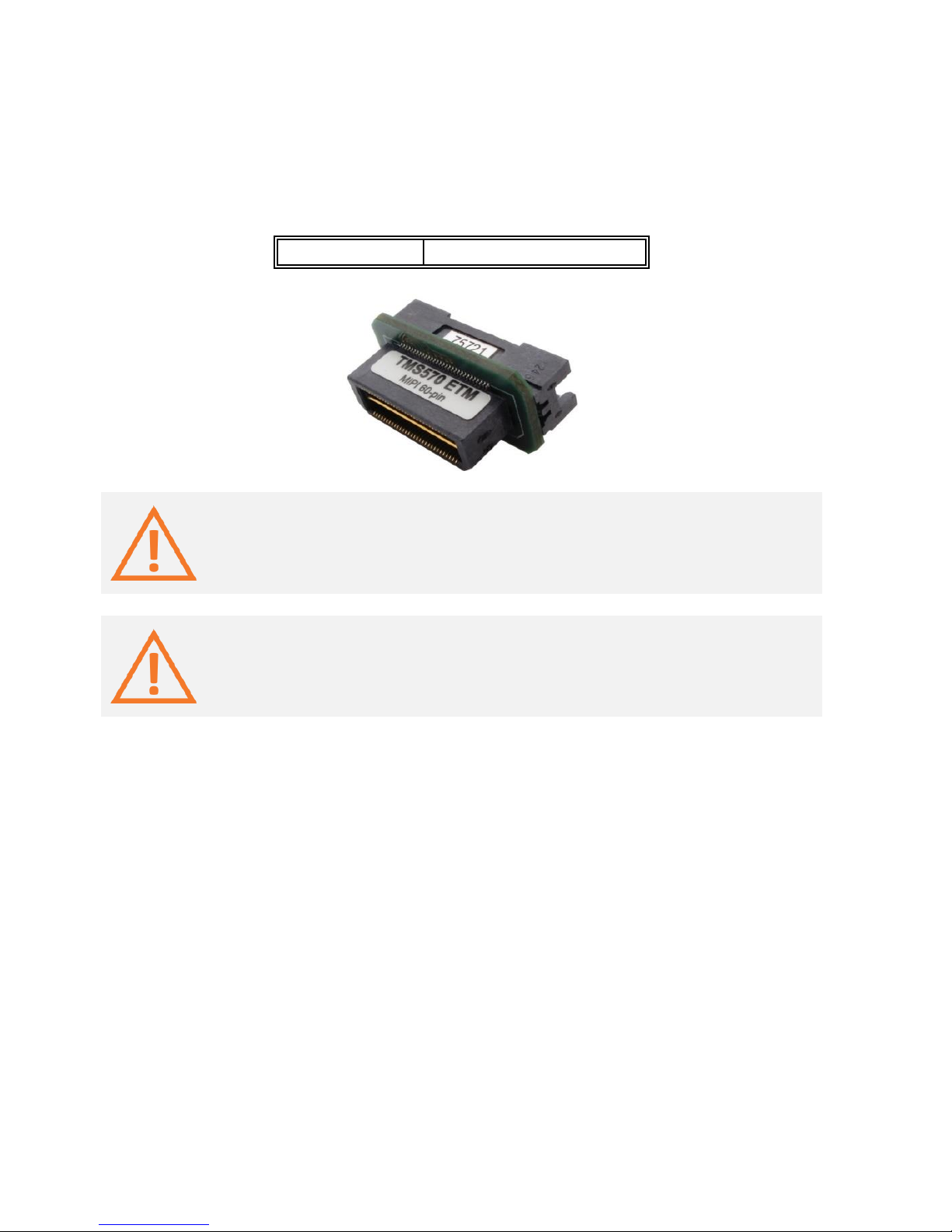
Texas Instruments 60-pin MIPI Adapter
Embedded targets based on Texas Instruments (TI) TMS570 microcontroller can feature Texas
Instruments 60-pin MIPI target debug connector with the TI proprietary pinout.
An adapter connecting at the end of the Mictor 38-pin ARM ETM 16-bit Debug Adapter is
available for Texas Instruments 60-pin MIPI pinout and must be ordered separately under the
IAMIC38MIPI60TMS570 ordering code.
Ordering code
IAMIC38MIPI60TMS570
The iC5000 and the iC5700 can trace up to 16 trace data lines. The target
microcontroller has to be configured for 16-bit trace port operation if the target
features 60-pin MIPI connector with 32 data trace lines connected.
Note that signal naming in iSYSTEM documentation uses target signal names and not
the ones from the MIPI standard. Refer to ‘MIPI Alliance Recommendation for Debug
and Trace Connectors’ and ‘ARM Target Interface Connections’ documentation for more
information about signal names and their functions.
The debug adapter connects to the target via a 60-pin MIPI connector, for example Samtec
QTH-030-01-L-D-A. A target should feature a matching part, for example Samtec QSH-030-01-LD-A.

10
The following pinout is valid on the target side:
Signal direction
Signal
Pin
Pin
Signal
Signal direction
I
VTref
1 2 TMS O O
TCK
3 4 TDO I O
TDI
5 6 nSRST O O
RTCK
7 8 nTRST_PD O O
nTRST_PU
9
10
NC
NC
11
12
NC I
TRACECLK
13
14
NC
NC
15
16
GND I
TRACECTL
17
18
NC I
TRACEDATA0
19
20
NC I
TRACEDATA1
21
22
NC I
TRACEDATA2
23
24
NC I
TRACEDATA3
25
26
NC I
TRACEDATA4
27
28
NC I
TRACEDATA5
29
30
NC I
TRACEDATA6
31
32
NC I
TRACEDATA7
33
34
NC I
TRACEDATA8
35
36
NC I
TRACEDATA9
37
38
NC I
TRACEDATA10
39
40
NC I
TRACEDATA11
41
42
NC I
TRACEDATA12
43
44
NC I
TRACEDATA13
45
46
NC I
TRACEDATA14
47
48
NC I
TRACEDATA15
49
50
NC
NC
51
52
NC
NC
53
54
NC
NC
55
56
NC
GND
57
58
GND
NC
59
60
NC
60-pin MIPI target pinout
Blue colored signals are trace signals.
This adapter can only be used in conjunction with the Mictor 38-pin ARM ETM 16-bit
Debug Adapter (ordering code IC50115).

11
10-pin 1.27mm Cortex Debug Adapter
Ordering code
IC50116-2
This debug adapter is used to connect the iC5000 and the iC5700 BlueBox to the Cortex-M
based target. It’s used to connect to the embedded target featuring a 10-pin 1.27mm target
debug connector with the Cortex-M pinout.
The debug adapter connects to the 25cm 40-pin ribbon cable coming from the BlueBox and to
the target debug connector on the other side. Refer to the BlueBox User Manual for more
details on connecting the debug adapter.
The following pinout is valid on the target side:
Signal direction
Signal
Pin
Pin
Signal
Signal direction
I
VTref
1 2 SWDIO/TMS
I/O
GND
3 4 SWCLK/TCK
O
GND
5 6 SWO/TDO
I
KEY
7 8 NC/TDI O
GND
9
10
nSRST
I/O
10-pin Cortex-M pinout
10-pin 1.27mm Cortex-M Debug Adapter features resettable fuses on pins 1, 2, 4, 6, 8 and 10.
These fuses protect debug signals against overcurrent and cycle back to a conductive state
after the excessive current fades away.
The debug adapter connects to the target through one of the two 10-pin 1.27mm connectors.
Note that only one is to be connected to the target!
The one at the end of the cable is with a so called “strain relief” option (Samtec FFSD-05-01-NSR) and is the robust type when it comes to connecting and disconnecting it from the target
very often. This is the recommended connection connector to be used. However, the
connector is a bit wider and therefore the target must have a matching part populated.
Matching part on the target side is e.g. Samtec ESHF-105-01-L-D (full frame connector) or
Samtec FTSH-105-01-F-DV-K (connector without the frame at the side).
The second connector is 1cm away from the first one toward the blue box and is a “standard”
type (Samtec FFSD-05-01-N). It’s much less robust and is prone to fail if the cable is not handled
cautiously or just connected/disconnected too many times. This connector should be used
when the target doesn’t provide the matching target connector for the “strain relief” type

12
connector. Matching part on the target is Samtec SHF-105-01-L-D or Samtec FTSH-105-01-FDV-K (connector without the frame at the side).
Recommendation for the target side connector is the FTSH-105-01-F-DV-K connector, which
matches the connector with and without the strain relief option.
Robust and less
prone to fail

13
If the 10-pin 1.27 mm pitch ribbon cable gets damaged, it can be ordered as a spare part under
the ordering code IA10PIN10PIN127.
IC50116-2 with detached 10-pin 1.27mm pitch ribbon cable
Optionally, a longer ribbon cable can be ordered under the ordering code IA10PIN10PIN127CUST. A cable length must be specified at the order. Note that the optional length should be
reasonable (e.g. 10 cm) since the quality of electrical signals degrades with prolonging the
cable. iSYSTEM gives no assurance for BlueBox operation with this cable. The cable is meant to
be used only for boundary cases where BlueBox cannot be connected to the target hardware
through the standard debug adapter, for example due to the physical obstacles of the target
system. In such cases, operating the BlueBox at lower JTAG scan speeds and not using the trace
functionality at all, might be still an acceptable compromise. It’s up to the user to thoroughly
test and qualify the BlueBox operation using custom length ribbon cable and to determine
working winIDEATM settings for his system.

14
10-pin 1.27mm Custom Cortex D. Adapter
Ordering code
IC50116-CUST2
This debug adapter is used to connect the iC5000 and the iC5700 BlueBox to the Cortex-M
based target. It’s used to connect to the embedded target featuring a 20-pin 1.27mm target
debug connector with the custom Cortex-M pinout. Optionally connecting the RTCK or the
JTAG TRST to pin 7 (KEY pin otherwise) makes this debug adapter distinct from the IC50116-2
debug adapter.
The debug adapter connects to the 25cm 40-pin ribbon cable coming from the BlueBox and to
the target debug connector on the other side. Refer to the BlueBox User Manual for more
details on connecting the debug adapter.
The following pinout is valid on the target side:
Signal direction
Signal
Pin
Pin
Signal
Signal direction
I VTref
1
2
SWDIO / TMS
I/O
GND
3
4
SWCLK / TCK
O
GND
5
6
SWO / TDO
I
KEY
7
8
NC / TDI
O I GND
9
10
nSRST
I/O
10-pin custom Cortex-M pinout
This debug adapter features custom Cortex-M pinout. When connecting the BlueBox to
the new embedded target for the first time, double check that the debug adapter
pinout matches with the target debug connector. Note that a mismatch can result in a
hardware failure.
Jumper J1
Jumper position 1-2: pin 7 = JTAG-TRST
Jumper position 3-2: pin 7 = RTCK
Jumper position floating: pin 7 = KEY (default)
10-pin 1.27mm Cortex-M debug adapter features resettable fuses on pins 1, 2, 4, 6, 8 and 10.
These fuses protect debug signals against overcurrent and cycle back to a conductive state
after the excessive current fades away.
The debug adapter connects to the target via a 10-pin 1.27mm connector, for example SAMTEC
FFSD-05-01-N. A target should feature a matching part, for example SAMTEC: SHF-105-01-L-DTH.

15
20-pin 1.27mm Cortex Debug Adapter
Ordering code
IC50118-2
This adapter is used to connect the iC5000 and the iC5700 development system to the CortexM based target. It’s used to connect to the embedded target featuring a 20-pin 1.27mm target
debug connector with the Cortex-M pinout.
The debug adapter connects to the 25cm 40-pin ribbon cable coming from the BlueBox and to
the target debug connector on the other side. Refer to the BlueBox User Manual for more
details on connecting the debug adapter.
The following pinout is valid on the target side:
Signal direction
Signal
Pin
Pin
Signal
Signal direction
I
VTref
1 2 SWDIO / TMS
I/O / O
GND
3 4 SWCLK / TCK
O
GND
5 6 SWO / TDO
I
KEY
7 8 NC / TDI
O
GND
9
10
nSRST
I/O
NC_CAPGND
11
12
TRCLK
I
NC_CAPGND
13
14
TRD0
I
GND
15
16
TRD1
I
GND
17
18
TRD2
I
GND
19
20
TRD3
I
20-pin Cortex-M pinout
Blue colored signals are parallel trace signals.
When connecting the BlueBox to the new embedded target for the first time, double
check that the debug adapter pinout matches with the target debug connector. Note
that a mismatch can result in a hardware failure.

16
20-pin 1.27mm Cortex-M Debug Adapter features resettable fuses on pins 1, 2, 4, 6, 8 and 10.
These protect debug signals against overcurrent and cycle back to a conductive state after the
excessive current fades away. Signals on pins 12, 14, 16, 18 and 20 are protected via 100 ohm
serial resistors.
The debug adapter connects to the target through one of the two 20-pin 1.27mm connectors.
Note that only one is to be connected to the target!
The one at the end of the cable is with a so called “strain relief” option (Samtec FFSD-10-01-NSR) and is the robust type when it comes to connecting and disconnecting it from the target
very often. This is the recommended debug tool connector to be used. However the connector
is a bit wider and therefore the target must have a matching part populated. Matching part on
the target side is e.g. Samtec ESHF-110-01-L-D (full frame connector) or Samtec FTSH-110-01-FDV-K (connector without the frame at the side).
The second connector is 1cm away from the first one toward the blue box and is a “standard”
type (Samtec FFSD-10-01-N). It’s much less robust and is prone to fail if the cable is not handled
cautiously or just connected/disconnected too many times. This connector should be used
when the target doesn’t provide the matching target connector for the “strain relief” type
connector. Matching part on the target is Samtec SHF-110-01-L-D or Samtec FTSH-110-01-FDV-K (connector without the frame at the side).
Recommendation for the target side connector is the FTSH-110-01-F-DV-K connector since it
matches with the connector with and without the strain relief option.

17
Robust, less
prone to fail

18
If the 20-pin 1.27 mm pitch ribbon cable gets damaged, it can be ordered as a spare part under
the ordering code IA20PIN20PIN127.
IC50118-2 with detached 20-pin 1.27mm pitch ribbon cable
Optionally, a longer ribbon cable can be ordered under the ordering code IA20PIN20PIN127CUST. A cable length must be specified at the order. Note that the optional length should be
reasonable (e.g. 10 cm) since the quality of electrical signals degrades with prolonging the
cable. iSYSTEM gives no assurance for BlueBox operation with this cable. The cable is meant to
be used only for boundary cases where BlueBox cannot be connected to the target hardware
through the standard debug adapter, for example due to the physical obstacles of the target
system. In such cases, operating the BlueBox at lower JTAG scan speeds and not using the trace
functionality at all, might be still an acceptable compromise. It’s up to the user to thoroughly
test and qualify the BlueBox operation using custom length ribbon cable and to determine
working winIDEATM settings for his system.

19
20-pin 1.27 x 2.54mm Compact TI-20 D. Adapter
Ordering code
IC50119
This debug adapter is used to connect the iC5000 and the iC5700 BlueBox to the Cortex-M
based target. It’s used to connect to the embedded target featuring a 20-pin 1.27 x 2.54 mm
target debug connector with the Compact TI-20 pinout.
The debug adapter connects to the 25cm 40-pin ribbon cable coming from the BlueBox and to
the target debug connector on the other side. Refer to the BlueBox User Manual for more
details on connecting the debug adapter.
The following pinout is valid on the target side:
Signal direction
Signal description
Signal
Pin
Pin
Signal
Signal description
Signal direction
O
Standard JTAG
TMS 1 2
nTRST
Standard JTAG
O
O
Standard JTAG
TDI 3 4
GND
Ground
I
Reference voltage
VTref
5 6 KEY
Not connected
I
Standard JTAG
TDO 7 8
GND
Ground
I
Return TCK
RTCK
9
10
GND
Ground
O
Standard JTAG
TCK
11
12
GND
Ground
I
Emulation pins
EMU0
13
14
EMU1
Emulation pins
I
I/O
System Reset
nSRST
15
16
GND
Ground
I
Emulation pins
EMU2
17
18
EMU3
Emulation pins
I
I
Emulation pins
EMU4
19
20
GND
Ground
20-pin Compact TI-20 pinout
When connecting the BlueBox to the new embedded target for the first time, double
check that the debug adapter pinout matches with the target debug connector. Note
that a mismatch can result in a hardware failure.

20
20-pin 1.27 x 2.54 mm Compact TI-20 Debug Adapter features resettable fuses on all pins
except for pin 9, 13, 14, 17-19. These fuses protect debug signals against overcurrent and cycle
back to a conductive state after the excessive current fades away. Signals on pins 13, 14, 17-19
are protected via 100 ohm serial resistors.
Jumpers J1 and J2
Jumpers J1 and J2 selects whether the EMU0 (J1) or the EMU1 (J2) is tied to pull-up (position 1-
2) or directly to the GND (position 2-3).
The EMU signals’ functions may vary from board to board. See target board manual and
schematics for more information on how to set the jumpers.
The debug adapter connects to the target via a 20-pin 1.27 x 2.54 mm connector, for example
Sullins Connector Solutions: SFH41-PPPB-D10-ID-BK. A target should feature a matching part,
for example Samtec FTR-110-51-G-D-P.

21
16-pin 1.27mm Custom ARM Debug Adapter
Ordering code
IC50120
This debug adapter is used to connect the iC5000 and the iC5700 BlueBox to the Cortex-M
based target. It’s used to connect to the embedded target featuring a 16-pin 1.27 mm pitch
target debug connector with the custom ARM pinout.
The debug adapter connects to the 25cm 40-pin ribbon cable coming from the BlueBox and to
the target debug connector on the other side. Refer to the BlueBox User Manual for more
details on connecting the debug adapter.
The following pinout is valid on the target side:
Signal direction
Signal
Pin
Pin
Signal
Signal direction
I TCK
1
2
GND
O
TMS
3
4
GND
I
TDO
5
6
GND
O
TDI
7
8
GND
O
TRST
9
10
GND
I
VREF
11
12
GND
O
PRESETn
13
14
GND
Q
NC
15
16
GND
16-pin custom ARM pinout
This debug adapter features custom ARM pinout. When connecting the BlueBox to the
new embedded target for the first time, double check that the debug adapter pinout
matches with the target debug connector. Note that a mismatch can result in a
hardware failure.
The debug adapter features resettable fuses on pins 1, 3, 5, 7, 9, 11 and 13. These protect
debug signals against overcurrent. These fuses cycle back to a conductive state after the
excessive current fades away.
The adapter connects to the target via a 16-pin 1.27mm connector, for example Samtec FFSD08-01-N. A target should feature a matching part, for example Samtec FTSH-108-01-F-DV-K.

22
14-pin 2.54mm MPC5xxx Debug Adapter
Ordering code
IC50150
This debug adapter is used to connect the iC5000 and the iC5700 BlueBox to the Cortex-M
based target. It’s used to connect to the embedded target featuring a 14-pin 2.54mm pitch
target debug connector with MPC5xxx/SPC5 pinout.
The debug adapter connects to the 25cm 40-pin ribbon cable coming from the BlueBox and to
the target debug connector on the other side. Refer to the BlueBox User Manual for more
details on connecting the debug adapter.
The following pinout is valid on the target side:
Signal direction
Signal
Pin
Pin
Signal
Signal direction
O
TDI
1 2 GND
I
TDO
3 4 GND O
TCK
5 6 GND
O
EVTIN
7 8 PORST* O I/O
nSRST
9
10
TMS
O
I
VTref
11
12
GND
NC
13
14
JCOMP
O
14-pin MPC5xxx & SPC5 target pinout
When connecting the BlueBox to the new embedded target for the first time, double
check that the debug adapter pinout matches with the target debug connector. Note
that a mismatch can result in a hardware failure.
14-pin 2.54mm MPC5xxx Debug Adapter features resettable fuses on all connected pins. These
protect debug signals against overcurrent and cycle back to a conductive state after the
excessive current fades away.
Mandatory pins on the microcontroller side are the GND, VDD, nSRST, TMS, TDI, TDO and TCK.

23
Pin 8 (Power on reset) is supported with the debug adapter revision C1 or newer.
The JCOMP pin is optional. Some microcontrollers don’t have this pin. Internally, this is actually
the JTAG TRST which resets the JTAG TAP state machine. Because the JTAG TAP state machine
can be reset also via the TMS and the TCK toggling, this pin is optional also for the debugger. If
microcontroller has the JCOMP pin but it is not connected to the target debug connector then
it must be set to non-active state in the target via a pull-up resistor. If not then the JTAG TAP
state machine remains in the reset state and debugging is not possible.
Jumper J1 (TCK)
If the TCK (debug JTAG clock) signal path from the target debug connector to the target
microcontroller is not designed as a single point to point connection, user may experience
signal integrity problems. For example, the TCK signal degrades electrically if it’s is routed to
multiple points, e.g. to the target microcontroller and also to some other IC(s), or expansion
connector(s) or even to another PCB. In such cases, signal integrity gets improved by adding a
buffer on the TCK driver side (J1: position 2-3).
Normally jumper J1 should be kept in default 1-2 position. When experiencing problems with
the initial debug connection or just unstable operation of the debugger, position 2-3 should be
tested.
Jumper J1 was introduced with the debug adapter revision D1. Previous versions A1, A2,
B1, C1 and C2 do not provide this jumper.
Jumper J2 (EVTIN)
Under some circumstances it can happen that the debugger cannot find any absolute program
counter message in the analyzed Nexus trace block. Consequentially, trace reconstruction fails
and errors or nothing gets displayed in the trace window. To avoid such situations, the
debugger can feed periodic signal to the EVTIN CPU pin connecting to the on-chip Nexus
engine, which then periodically generates and broadcasts program counter synchronization
messages.
In order to use this feature, the jumper J2 must be bridged and the ‘Force periodic Nexus SYNC’
option in the ‘Hardware/emulation Options/CPU Setup/Nexus’ tab must be checked. Refer to
iSYSTEM ‘Freescale MPC5xxx & ST SPC56 Family On-Chip Emulation’ technical notes document
for more details on the ‘Force periodic Nexus SYNC’ option use.
Note that the EVTI (Nexus Event In) CPU pin may be shared with other CPU functionalities. For
instance, on the MPC5516 the same pin can operate as the GPIO, the EBI read/write or the
EVTI. Whenever the CPU pin is configured and used for the EVTI alternate operation, the
jumper J2 must not be populated in order to prevent electrical conflicts.
Typically there is no need to use the ‘Force periodic Nexus SYNC’ functionality unless a
specific application code is traced, which does not generate messages containing
absolute program counter information. As long as the user has no problems with the
trace use, it is recommended to keep the jumper J2 disconnected.

24
Jumper J2 was introduced with the debug adapter revision C1. Previous versions A1, A2,
B1 and D1 don’t provide this jumper.
The debug adapter connects to the target via a 14-pin 2.54 mm connector, for example
Yamaichi FAS-1401-2101-2-0BF. A target should feature a matching part, for example WÜRTH
ELEKTRONIK: 612 014 216 21.
ECU14 JTAG 10-pin 1.27mm Adapter
The ECU14 connector standard has been defined by Bosch and can feature either the JTAG or
the DAP debug interface.
An adapter connecting at the end of the 14-pin 2.54mm MPC5xxx Debug Adapter is available
for the MPC5xxx/SPC5 embedded target featuring the ECU14 10-pin 1.27mm connector and
must be ordered separately under the IAMPC_TC2ECU14 ordering code. Toward the BlueBox
the adapter features 14-pin 2.54 mm male connector featuring the MPC5xxx/SPC5 JTAG debug
interface and 16-pin 2.54 mm male connector featuring Infineon JTAG debug interface.
Ordering code
IAMPC_TC2ECU14
The following pinout is valid on the target side:
Signal direction
Signal
Pin
Pin
Signal
Signal direction
GND
1 2 TCLK
O
O
~TRST
3 4 TDO I O
TMS
5 6 TDI
O
I/O
USERIO
7 8 Vref I
NC
9
10
~RESET
O
10-pin Bosch ECU14 target pinout
When connecting the BlueBox to the new embedded target for the first time, double
check that the debug adapter pinout matches with the target debug connector. Note
that a mismatch can result in a hardware failure.

25
Jumper J2
The jumper J2 is optional and by default not populated. It connects 10k pull-down resistor to
the USERIO pin when bridged.
The jumper has been introduced for a custom target, where the target watchdog gets disabled
during the debugging, when low level at the USERIO signal (target debug connector pin 7) is
detected.
The debug adapter connects to the target via a 10-pin 1.27mm connector, Samtec SFM-105-01S-D). A target should feature a matching part, for example Samtec TFM-105-01-L-D.
This adapter is used only in conjunction with the 14-pin 2.54mm MPC5xxx Debug
Adapter (ordering code IC50150) and optionally with the 16-pin 2.54mm Infineon JTAG
Debug Adapter (ordering code IC50160).

26
38-pin Mictor MPC5xxx Nexus 16-bit D. Adapter
Ordering code
IC50152
IC50152-12
This debug adapter is used to connect the iC5000 and the iC5700 BlueBox to Freescale
MPC5xxx or ST SPC5 based target. It’s used to connect to the embedded target featuring a 38pin Mictor target debug connector with the MPC5xxx Nexus pinout.
The debug adapter connects to the BlueBox through the two ribbon cables and to the target
debug connector on the other side. Refer to the BlueBox User Manual for more details on
connecting the debug adapter.
The debug adapter under the IC50152 ordering code features a standard ribbon cable length,
which is cca. 24 cm. A debug adapter with shorter cable length (12 cm) has been introduced
(ordering code IC50152-12) for situations when standard length doesn’t work e.g. due to a
badly designed target board layout where reliable Nexus trace capture with the standard 24 cm
ribbon cable cannot be achieved. In such situations shorter cable usually helps.
Jumper J2 (EVTIN)
Under some circumstances it can happen that the debugger cannot find any absolute program
counter message in the analyzed Nexus trace stream. Consequentially, the program trace
reconstruction fails and errors or nothing gets displayed in the trace window. To avoid such
situations, the BlueBox can feed periodic signal to the EVTIN CPU pin connecting to the on-chip
Nexus trace engine, which then periodically generates and broadcasts program counter
synchronization messages.
In order to use this feature, the jumper J2 must be bridged and the ‘Force periodic Nexus SYNC’
option in the ‘Hardware/emulation Options/CPU Setup/Nexus’ tab must be checked in
winIDEATM. Refer to iSYSTEM ‘Freescale MPC5xxx & ST SPC56 Family On-Chip Emulation’
technical notes document for more details on the ‘Force periodic Nexus SYNC’ option use.
Note that the EVTI (Nexus Event In) CPU pin may be shared with other CPU functionalities. For
instance, on the MPC5516 the same pin can operate as the GPIO, the EBI read/write or the
EVTI. Whenever the CPU pin is configured and used for the EVTI alternate operation, the J2
must not be populated in order to prevent electrical conflicts.

27
Typically there is no need to use the ‘Force periodic Nexus SYNC’ functionality unless a
specific application code is traced, which does not generate messages containing
absolute program counter information. As long as the user has no problems with the
trace use, it is recommended to keep the jumper J2 disconnected.
Jumper J2 was introduced with the debug adapter revision N1. Earlier versions don’t
provide this jumper.
The following pinout is valid on the target side:
Signal direction
Signal
Pin
Pin
Signal
Signal direction
I
MDO12
1 2 MDO13 I I
MDO14
3 4 MDO15
I
I
MDO9
5 6 NC
NC
7 8 MDO8
I
I/O
RSTIN
9
10
EVTIN O I
TDO
11
12
VTREF
I
I
MDO10
13
14
NC I O
TCK
15
16
MDO7
I
O
TMS
17
18
MDO6 I O
TDI
19
20
MDO5
I
O
NTRST
21
22
MDO4 I I
MDO11
23
24
MDO3
I
NC
25
26
MDO2 I
NC
27
28
MDO1
I
NC
29
30
MDO0 I
NC
31
32
EVTO
I
NC
33
34
MCKO I
NC
35
36
MSEO1
I
NC
37
38
MSEO0
I
MPC5xxx and SPC56 16-bit Nexus target pinout
Blue colored signals are trace signals.
When connecting the BlueBox to the new embedded target for the first time, double
check that the debug adapter pinout matches with the target debug connector. Note
that a mismatch can result in a hardware failure.
38-pin Mictor MPC5xxx Nexus 16-bit Debug Adapter features resettable fuses on pins 9, 10, 11,
12, 15, 17, 19 and 21. These protect debug signals against overcurrent and cycle back to a
conductive state after the excessive current fades away. Signals on pins 1, 2, 3, 4, 5, 8, 13, 14,
16, 18, 20, 22, 23, 24, 26, 28, 30, 32, 34, 36 and 38 are protected via 47 ohm serial resistors.
The debug adapter connects to the target via a 38-pin Mictor connector, Tyco Electronics
5767055-1. A target should feature a matching part, for example Tyco Electronics 5767081-1 in
the SMT technology.

28
50-pin ERF8 MPC5xxx Nexus Adapter
Ordering code
IAMIC38SAM50MPC
IAMIC38SAM50MPC adapter
Some targets based on Freescale Qorivva Power Architecture or PX Series Power Architecture
microcontroller(s) (e.g. MPC5675K) can also feature a 50-pin Samtec ERF8 connector for the
Nexus debug interface instead of the popular 38-pin Mictor connector. In this case, the
IAMIC38SAM50MPC adapter is connected to the target first and then used in conjunction with
the 38-pin Mictor MPC5xxx Nexus 16-bit Debug Adapter.
It has been noticed that the 50-pin Samtec ERF8 target connector may not always
provide good mechanical stability in a vertical direction which can in worst case yield an
unreliable debug connection. Special care must be taken when connecting this debug
adapter to the target to prevent potential connection problems.

29
The following pinout is valid on the target side:
Signal direction
Signal
Pin
Pin
Signal
Signal direction
I
MSEO0
1 2 VTREF I
MSEO1
3 4 TCK
O
GND
5 6 TMS O I
MDO0
7 8 TDI
O
I
MDO1
9
10
TDO I
GND
11
12
nTRST
O
I
MDO2
13
14
NC I
MDO3
15
16
EVTI
O
GND
17
18
EVTO I I
MCKO
19
20
nSRST
O
I
MDO4
21
22
NC O
GND
23
24
GND
I
MDO5
25
26
NC I
MDO6
27
28
NC
GND
29
30
GND I
MDO7
31
32
NC
I
MDO8
33
34
NC
GND
35
36
GND
I
MDO9
37
38
NC I
MDO10
39
40
NC
GND
41
42
GND I
MDO11
43
44
MDO13
I
I
MDO12
45
46
MDO14 I
GND
47
48
GND
I
MDO15
49
50
NC
50-pin Samtec ERF8 MPC5xxx Nexus target pinout
Blue colored signals are trace signals.
When connecting the BlueBox to the new embedded target for the first time, double
check that the debug adapter pinout matches with the target debug connector. Note
that a mismatch can result in a hardware failure.
The debug adapter connects to the target via a 50-pin Samtec ERM8 connector, Samtec ERM8025-01-L-D-EM2-TR. A target should feature a matching part, for example Samtec ERF8-025-
05.0-L-DV.

30
50-pin ERF8 MPC5xxx Nexus 16-bit D. Adapter
Ordering code
IC50156
This debug adapter is used to connect the iC5000 and the iC5700 BlueBox to Freescale
MPC5xxx or ST SPC56 based target featuring a 50-pin Samtec ERF8 target debug connector
with the MPC5xxx Nexus pinout.
The debug adapter connects to the BlueBox through the two ribbon cables and to the target
debug connector on the other side. Refer to the BlueBox User Manual for more details on
connecting the debug adapter.
It has been noticed that the 50-pin Samtec ERF8 target connector may not always
provide good mechanical stability in a vertical direction which can in worst case yield an
unreliable debug connection. Special care must be taken when connecting this debug
adapter to the target to prevent potential connection problems.
Jumper J2 (EVTIN)
Under some circumstances it can happen that the debugger cannot find any absolute program
counter message in the analyzed Nexus trace stream. Consequentially, the program trace
reconstruction fails and errors or nothing gets displayed in the trace window. To avoid such
situations, the BlueBox can feed periodic signal to the EVTIN CPU pin connecting to the on-chip
Nexus trace engine, which then periodically generates and broadcasts program counter
synchronization messages.
In order to use this feature, the jumper J2 must be bridged and the ‘Force periodic Nexus SYNC’
option in the ‘Hardware/emulation Options/CPU Setup/Nexus’ tab must be checked in
winIDEATM. Refer to iSYSTEM ‘Freescale MPC5xxx & ST SPC56 Family On-Chip Emulation’
technical notes document for more details on the ‘Force periodic Nexus SYNC’ option use.
Note that the EVTI (Nexus Event In) CPU pin may be shared with other CPU functionalities. For
instance, on the MPC5516 the same pin can operate as the GPIO, the EBI read/write or the
EVTI. Whenever the CPU pin is configured and used for the EVTI alternate operation, the J2
must not be populated in order to prevent electrical conflicts.

31
Typically there is no need to use the ‘Force periodic Nexus SYNC’ functionality unless a
specific application code is traced, which does not generate messages containing
absolute program counter information. As long as the user has no problems with the
trace use, it is recommended to keep the jumper J2 disconnected.
The following pinout is valid on the target side:
Signal direction
Signal
Pin
Pin
Signal
Signal direction
I
MSEO0
1 2 VTREF I
MSEO1
3 4 TCK
O
GND
5 6 TMS O I
MDO0
7 8 TDI
O
I
MDO1
9
10
TDO I
GND
11
12
nTRST
O
I
MDO2
13
14
NC I
MDO3
15
16
EVTI
O
GND
17
18
EVTO I I
MCKO
19
20
nSRST
O
I
MDO4
21
22
NC O
GND
23
24
GND
I
MDO5
25
26
NC I
MDO6
27
28
NC
GND
29
30
GND I
MDO7
31
32
NC
I
MDO8
33
34
NC
GND
35
36
GND
I
MDO9
37
38
NC I
MDO10
39
40
NC
GND
41
42
GND I
MDO11
43
44
MDO13
I
I
MDO12
45
46
MDO14 I
GND
47
48
GND
I
MDO15
49
50
NC
50-pin Samtec ERF8 MPC5xxx Nexus target pinout
Blue colored signals are trace signals.
When connecting the BlueBox to the new embedded target for the first time, double
check that the debug adapter pinout matches with the target debug connector. Note
that a mismatch can result in a hardware failure.
50-pin ERF8 MPC5xxx Nexus 16-bit Debug Adapter features resettable fuses on pins 2, 4, 6, 8,
10, 12, 16 and 20. These protect debug signals against overcurrent and cycle back to a
conductive state after the excessive current fades away. All other signals are protected via the
47 ohm serial resistor.
The debug adapter connects to the target via a 50-pin Samtec connector, Samtec ERM8-02501-L-D-EM2. A target should feature a matching part, for example Samtec ERF8-025-05.0-L-DV
in the SMT technology.

32
16-pin 2.54mm Infineon JTAG Debug Adapter
Ordering code
IC50160
This debug adapter is used to connect the iC5000 and the iC5700 BlueBox to Infineon TriCore
and XC2000/XC166 based target featuring a 16-pin 2.54mm pitch target debug connector with
Infineon JTAG pinout.
The debug adapter connects to the 25cm 40-pin ribbon cable coming from the BlueBox and to
the target debug connector on the other side. Refer to the BlueBox User Manual for more
details on connecting the debug adapter.
The following pinout is valid on the target side:
Signal
direction
Signal description
Signal
Pin
Pin
Signal
Signal description
Signal
direction
O
Standard JTAG
TMS
1 2 VTref
Reference voltage
I
I
Standard JTAG
TDO
3 4 GND
Ground
O (optional)
CPUCLK
5 6 GND
Ground
O Standard JTAG
TDI
7 8 RESET
Power On Reset
O O Standard JTAG
TRST
9
10
BRK_OUT
Break Output
I I Standard JTAG
TCLK
11
12
GND
Ground
O Break Input
BRK_IN
13
14
OCDS_E
(optional)
O Not Connected
NC
15
16
NC
Not Connected
16-pin Infineon JTAG target pinout
When connecting the BlueBox to the new embedded target for the first time, double
check that the debug adapter pinout matches with the target debug connector. Note
that a mismatch can result in a hardware failure.
16-pin 2.54mm Infineon JTAG Debug Adapter features resettable fuses on all connected pins.
These protect debug signals against overcurrent and cycle back to a conductive state after the
excessive current fades away.
Mandatory pins on the microcontroller side are TMS, TDO, TDI, TRST, TCLK and RESET. BRK_IN
and BRK_OUT signals can be used optionally.
The debug adapter connects to the target via a 16-pin 2.54 mm connector, Yamaichi FAS-16012101-2-OBF. A target should feature a matching part, for example WÜRTH ELEKTRONIK
61201621621.

33
10-pin 1.27mm Tricore ECU14 Debug Adapter
Ordering code
IC50160-ECU14
This connector has been defined by Bosch and supports the JTAG and the DAP debug interface.
This debug adapter is used to connect the iC5000 and the iC5700 BlueBox to Infineon TriCore
and XC2000/XC166 based target featuring a 10-pin 1.27mm pitch target debug connector with
Bosch ECU14 pinout.
This debug adapter supports only the JTAG debug interface. It doesn’t support the DAP
debug interface.
The debug adapter connects to the 25cm 40-pin ribbon cable coming from the BlueBox and to
the target debug connector on the other side. Refer to the BlueBox User Manual for more
details on connecting the debug adapter.
The following pinout is valid on the target side:
Signal direction
Signal description
Signal
Pin
Pin
Signal
Signal description
Signal direction
Ground
GND 1 2
TCLK
Standard JTAG
O
O
Standard JTAG
~TRST
3 4 TDO
Standard JTAG
I
O
Standard JTAG
TMS 5 6
TDI
Standard JTAG
O
I/O
User specific
USERIO
7 8 Vref
Reference voltage
I
Not Connected
NC 9 10
~RESET
Power On Reset
O
10-pin Bosch ECU14 target pinout
When connecting the BlueBox to the new embedded target for the first time, double
check that the debug adapter pinout matches with the target debug connector. Note
that a mismatch can result in a hardware failure.

34
10-pin 1.27mm TriCore ECU14 Debug Adapter features resettable fuses on all connected pins.
These protect debug signals against overcurrent and cycle back to a conductive state after the
excessive current fades away. Mandatory pins on the microcontroller side are the TMS, the
TDO, the TDI, the ~TRST, the TCLK and the ~RESET. The USERIO signal is used optionally.
Pin 1 position
The pin next to the alignment pin is pin 10 and not pin 1!
The pin 1 position is marked with a small white square on the PCB. Additionally the pin is
marked with a number 1 directly on the debug adapter target connector from revision C1 on.
Jumper J1
The jumper J1 has been put on the debug adapter only for making provision for future
extensions of the “ECU14” target connection.
The USERIO signal (target debug connector pin 7) is connected to the BlueBox output (J1 in the
position 1-2) or to the BlueBox input (J1 in the position 2-3). Currently the signal has no
functionality and consequentially the J1 is not populated.
Jumper J2
The jumper J2 is optional and by default not populated. It connects 10k pull-down resistor to
the USERIO pin when bridged.
The jumper has been introduced for a custom target, where the target watchdog gets disabled
during the debugging, when low level at the USERIO signal (target debug connector pin 7) is
detected.
The debug adapter connects to the target via a 10-pin 1.27mm connector, Samtec SFM-105-01S-D. A target should feature a matching part, for example Samtec TFM-105-01-L-D.

35
10-pin 1.27mm Tricore MEDC17 Debug Adapter
Ordering code
IC50160-MEDC17
This connector has been defined by Bosch and supports the JTAG debug interface only.
This debug adapter is used to connect the iC5000 and the iC5700 BlueBox to Infineon TriCore
and XC2000/XC166 based target (via the JTAG debug interface) featuring a 10-pin 1.27mm
pitch target debug connector with Bosch MEDC17 pinout.
The debug adapter connects to the 25cm 40-pin ribbon cable coming from the BlueBox and to
the target debug connector on the other side. Refer to the BlueBox User Manual for more
details on connecting the debug adapter.
The following pinout is valid on the target side:
Signal
direction
Signal description
Signal
Pin
Pin
Signal
Signal description
Signal
direction
O
Break Input
~BRK_IN
1 2 ~TRST
Standard JTAG
O
Ground
GND
3 4 TCLK
Standard JTAG
O O Standard JTAG
TMS
5 6 ~BRK_OUT
Break Output
I
O
Power On Reset
~RESET
7 8 TDI
Standard JTAG
O I Reference voltage
VTref
9
10
TDO
Standard JTAG
I
10-pin Bosch MEDC17 target pinout
When connecting the BlueBox to the new embedded target for the first time, double
check that the debug adapter pinout matches with the target debug connector. Note
that a mismatch can result in a hardware failure.
10-pin 1.27mm Tricore MEDC17 Debug Adapter features resettable fuses on all connected pins.
These protect debug signals against overcurrent and cycle back to a conductive state after the
excessive current fades away.
Mandatory pins on the microcontroller side are TMS, TDO, TDI, ~TRST, TCLK and ~RESET.
~BRK_IN and ~BRK_OUT signals can be used optionally.
The debug adapter connects to the target via a 10-pin 1.27mm connector, Samtec FFSD-05-01N. A target should feature a matching part, for example Samtec SHF-105-01-L-D-TH.

36
6-pin 2.54mm Infineon I2C Debug Adapter
Ordering code
IC50162
This debug adapter is used to connect the iC5000 and the iC5700 BlueBox to Infineon
SP37/SP40 based target featuring a 6-pin 2.54mm pitch target debug connector with Infineon
I2C pinout.
The debug adapter connects to the 25cm 40-pin ribbon cable coming from the BlueBox and to
the target debug connector on the other side. Refer to the BlueBox User Manual for more
details on connecting the debug adapter.
The following pinout is valid on the target side:
Pin
Signal
Signal description
Signal direction
1
VDDBAT
Reference voltage
2
PP0 I/O
3
PP1 I/O
4
GND
Ground
5
PP2 I/O
6
PP3 I/O
6-pin 2.54mm Infineon I2C pinout
When connecting the BlueBox to the new embedded target for the first time, double
check that the debug adapter pinout matches with the target debug connector. Note
that a mismatch can result in a hardware failure.
6-pin 2.54mm Infineon I2C Debug Adapter features resettable fuses on pins 1, 2, 3, 4, 5 and 6.
These fuses protect debug signals against overcurrent and cycle back to a conductive state
after the excessive current fades away.
Emulation Notes
The MCU can run in normal, debug or programming mode. Mode is always selected after
power-on and cannot be changed later. Because of this the VDDBAT (pin 1 on the debug
connector) is a power supply output from the emulator and the target power supply (battery)
must be removed while debugging. Before the debug download takes place, power off/on
sequence is generated by the emulator and programming mode selected. During the debug

37
download, first user flash is erased, then the application code programmed into the flash and
at the end the complete flash is read back. This last step is required since the code memory can
be no longer read once the MCU is in the debug mode. Beside of the user flash, the SP41 has
also the Firmware ROM which cannot be read by the debugger.
After the debug download, the MCU is reset again since it was in the programming mode
during the debug download. This means a power off/on sequence is initiated again and the
debug mode selected. This same sequence is also applied when debug reset command is
executed from winIDEATM.
During the debugging (the MCU in the debug mode) two hardware execution breakpoints are
available. No software breakpoints in flash are available since the user flash cannot be
modified in the debug mode.
Real time access is not available.
On-chip debug logic does not implement a stop command. Therefore the MCU cannot be
stopped by the debugger while the application is running. The MCU will stop only if hardware
execution breakpoint is hit.
Note: The 4-pin “connector” located on the side of the debug adapter is meant for future
extensions of debug functionalities. Currently it provides no functionality.
The debug adapter connects to the target via a 6-pin 2.54 mm connector, LUMBERG: 2,5 MBX
06. A target should feature a matching part, for example WÜRTH ELEKTRONIK: 613 006 111 21.

38
10-pin 1.27mm Infineon DAP2 Wide D. Adapter
Ordering code
IC50163-2
This debug adapter is used to connect the iC5000 and the iC5700 BlueBox to Infineon TriCore
and XC2000/XC166 based target featuring a 10-pin 1.27mm pitch target debug connector with
Infineon DAP pinout.
The debug adapter connects to the BlueBox through the two ribbon cables and to the target
debug connector on the other side. Refer to the BlueBox User Manual for more details on
connecting the debug adapter.
Jumper J1
With the jumper J1 in the position 1-2 (default), normal debug operation is configured. The
debugger drives the MCU reset line low during the initial debug connection and then takes
control over the microcontroller.
With the jumper J1 in the position 2-3, the Hot Attach operation is configured. In this case, all
debug signals from the BlueBox are disconnected and the target starts running as soon as the
power is applied to the target. When the Hot Attach command is issued from winIDEATM, the
debugger connects to the MCU and control over the MCU is taken without resetting the MCU.
Refer to the TriCore technical notes document for more details on the Hot Attach configuration
and use.
The following pinout is valid on the target side:
Signal
direction
Signal description
Signal
Pin
Pin
Signal
Signal description
Signal
direction
I
Reference voltage
Vref
1 2 DAP1
Bidirectional data
I/O Ground
GND
3 4 DAP0
DAP clock
O Ground
GND
5 6 DAP2
Bidirectional data
I/O
Not Connected
NC
7 8 USER_IN
Optional
O Ground
GND
9
10
RESET
System Reset
I/O
10-pin Infineon DAP pinout
When connecting the BlueBox to the new embedded target for the first time, double
check that the debug adapter pinout matches with the target debug connector. Note
that a mismatch can result in a hardware failure.

39
10-pin 1.27mm Infineon DAP Debug Adapter features resettable fuses on pins 1, 2, 3, 4, 5, 6, 8,
9 and 10. These fuses protect debug signals against overcurrent and cycle back to a conductive
state after the excessive current fades away.
The debug adapter connects to the target through one of the two 10-pin 1.27mm connectors.
Note that only one is to be connected to the target!
The one at the end of the cable is with a so called “strain relief” option (Samtec FFSD-05-01-NSR) and is the robust type when it comes to connecting and disconnecting it from the target
very often. This is the recommended connection connector to be used. However, the
connector is a bit wider and therefore the target must have a matching part populated.
Matching part on the target side is e.g. Samtec ESHF-105-01-L-D (full frame connector) or
Samtec FTSH-105-01-F-DV-K (connector without the frame at the side).
The second connector is 1cm away from the first one toward the blue box and is a “standard”
type (Samtec FFSD-05-01-N). It’s much less robust and is prone to fail if the cable is not handled
cautiously or just connected/disconnected too many times. This connector should be used
when the target doesn’t provide the matching target connector for the “strain relief” type
connector. Matching part on the target is Samtec SHF-105-01-L-D or Samtec FTSH-105-01-FDV-K (connector without the frame at the side).
Recommendation for the target side connector is the FTSH-105-01-F-DV-K connector, which
matches the connector with and without the strain relief option.

40
Robust and less
prone to fail
If the 10-pin 1.27 mm pitch cable gets damaged, it can be ordered as a spare part under the
ordering code IA10PIN10PIN127.

41
IC50163-2 with the detached 10-pin 1.27mm pitch cable
Optionally, a longer ribbon cable can be ordered under the ordering code IA10PIN10PIN127CUST. A cable length must be specified at the order. Note that the optional length should be
reasonable (e.g. 10 cm) since the quality of electrical signals degrades with prolonging the
cable. iSYSTEM gives no assurance for BlueBox operation with this cable. The cable is meant to
be used only for boundary cases where BlueBox cannot be connected to the target hardware
through the standard debug adapter, for example due to the physical obstacles of the target
system. In such cases, operating the BlueBox at lower JTAG scan speeds and not using the trace
functionality at all, might be still an acceptable compromise. It’s up to the user to thoroughly
test and qualify the BlueBox operation using custom length ribbon cable and to determine
working winIDEATM settings for his system.

42
22-pin ERF8 DAP2 Debug Adapter
Ordering code
IC50164
This debug adapter is used to connect the iC5000 and the iC5700 BlueBox to Infineon Aurix
based target providing Aurora trace interface along the DAP debug interface and featuring a
22-pin Samtec ERF8 target debug connector with the 22-pin ERF8 Aurix target pinout.
The debug adapter connects to the BlueBox through the two ribbon cables and to the target
debug connector on the other side. Refer to the BlueBox User Manual for more details on
connecting the debug adapter.
With the jumper J1 in the position 1-2 (default), normal debug operation is configured. The
debugger drives the MCU reset line low during the initial debug connection and then takes
control over the microcontroller.
With the jumper J1 in the position 2-3, the Hot Attach operation is configured. In this case, all
debug signals from the BlueBox are disconnected and the target starts running as soon as the
power is applied to the target. When the Hot Attach command is issued from winIDEATM, the
debugger connects to the MCU and control over the MCU is taken without resetting the MCU.
Refer to the TriCore technical notes document for more details on the Hot Attach configuration
and use.
The following pinout is valid on the target side:
Signal direction
Signal
Pin
Pin
Signal
Signal direction
Not Connected
1 2 Vref
I
Not Connected
3 4 DAP0
O
Ground
GND
5 6 DAP1
I/O
Not Connected
7 8 Not Connected
Not Connected
9
10
DAP2
I/O
Ground
GND
11
12
~TRST
O
Not Connected
13
14
Not Connected
Not Connected
15
16
Not Connected
Ground
GND
17
18
Not Connected
Not Connected
19
20
Not Connected
Not Connected
21
22
RESET
I/O
22-pin ERF8 Aurix target pinout

43
When connecting the BlueBox to the new embedded target for the first time, double
check that the debug adapter pinout matches with the target debug connector. Note
that a mismatch can result in a hardware failure.
22-pin ERF8 DAP2 Debug Adapter features resettable fuses on pins 2, 4, 5, 6, 10, 11, 12, 17 and
22. These fuses protect debug signals against overcurrent and cycle back to a conductive state
after the excessive current fades away.
The debug adapter connects to the target via a 22-pin ERF8 connector, Samtec ASP-137971-02.
The target must have populated a matching part, for example Samtec ASP-137969-01, Samtec
Series ERF8, Rugged High Speed Socket.

44
20-pin 2.54mm Renesas V850/RH850 D. Adapter
Ordering code
IC50171
This debug adapter is used to connect the iC5000 and the iC5700 BlueBox to Renesas RH850
based target featuring a 20-pin 2.54 mm pitch target debug connector with the V850/RH850
pinout.
The debug adapter connects to the 25cm 40-pin ribbon cable coming from the BlueBox and to
the target debug connector on the other side. Refer to the BlueBox User Manual for more
details on connecting the debug adapter.
The following pinout is valid on the target side:
Signal direction
Signal description
Signal
Pin
Pin
Signal
Signal description
Signal direction
Ground
GND 1 2
TCK
Debug JTAG
O
Ground
GND 3 4
TMS
Debug JTAG
O Ground
GND 5 6
TDI
Debug JTAG
O
Ground
GND 7 8
TRST
Debug JTAG
O Ground
GND
9
10
NC
Not Connected
Ground
GND
11
12
RESET
CPU Reset
I/O
Ground
GND
13
14
FLMD0
Flash Mode
O
Ground
GND
15
16
~RDY
Synchronization
I Ground
GND
17
18
TDO
Debug JTAG
I
Ground
GND
19
20
VDD
Reference voltage
I
20-pin V850/RH850 target pinout
When connecting the BlueBox to the new embedded target for the first time, double
check that the debug adapter pinout matches with the target debug connector. Note
that a mismatch can result in a hardware failure.
20-pin 2.54mm V850/RH850 Debug Adapter features resettable fuses on all pins except for pin
16. These fuses protect debug signals against overcurrent and cycle back to a conductive state
after the excessive current fades away. A signal on pin 16 is protected via 100 ohm serial
resistor.
The debug adapter connects to the target via a 20-pin 2.54 mm connector, Yamaichi FAS-20012101-2-OBF. A target should feature a matching part, for example WÜRTH ELEKTRONIK
61202021621.

45
14-pin 2.54mm Renesas RH850 Debug Adapter
Ordering code
IC50176
This debug adapter is used to connect the iC5000 and the iC5700 BlueBox to Renesas RH850
based target featuring a 14-pin 2.54 mm pitch target debug connector with the RH850 pinout.
The debug adapter connects to the 25cm 40-pin ribbon cable coming from the BlueBox and to
the target debug connector on the other side. Refer to the BlueBox User Manual for more
details on connecting the debug adapter.
The following pinout is valid on the target side:
Signal
direction
Signal description
Signal
Pin
Pin
Signal
Signal description
Signal
direction
O
Debug JTAG
TCK
1 2 GND
Ground
O
Debug JTAG
TRST
3 4 FLMD0
Flash Mode
O I Debug JTAG
TDO
5 6 FLMD1
Flash Mode
O
O
Debug JTAG
TDI
7 8 VTREF
Reference voltage
I O Debug JTAG
TMS
9
10
NC
Not Connected
I
Synchronization
~RDY
11
12
GND
Ground
I/O
CPU Reset
RESET
13
14
GND
Ground
14-pin RH850 target pinout
When connecting the BlueBox to the new embedded target for the first time, double
check that the debug adapter pinout matches with the target debug connector. Note
that a mismatch can result in a hardware failure.
14-pin 2.54mm RH850 Debug Adapter features resettable fuses on all pins except for pin 11.
These fuses protect debug signals against overcurrent and cycle back to a conductive state
after the excessive current fades away. A signal on pin 11 is protected via 22 ohm serial
resistor.
The debug adapter connects to the target via a 14-pin 2.54 mm connector, Yamaichi FAS-14012101-2-OBF. A target should feature a matching part, for example WÜRTH ELEKTRONIK
61201421621.

46
10-pin 1.27mm Renesas RH850 Debug Adapter
Ordering code
IC50176-EPS
This debug adapter is used to connect the iC5000 and the iC5700 BlueBox to Renesas RH850
based target featuring a 10-pin 1.27 mm pitch target debug connector with the RH850
proprietary (EPS) pinout.
The debug adapter connects to the 25cm 40-pin ribbon cable coming from the BlueBox and to
the target debug connector on the other side. Refer to the BlueBox User Manual for more
details on connecting the debug adapter.
The following pinout is valid on the target side:
Signal direction
Signal
Pin
Pin
Signal
Signal direction
I
JP05/RDY
1 2 RESET
I/O
O
JP02/TCK
3 4 JP00/TDI
O
O
JP03/TMS
5 6 JP04/TRST
O
I
JP01/TDO
7 8 FLMD0
O
3V3
9
10
GND
10-pin RH850 proprietary (EPS) target pinout
When connecting the BlueBox to the new embedded target for the first time, double
check that the debug adapter pinout matches with the target debug connector. Note
that a mismatch can result in a hardware failure.
10-pin 1.27mm RH850 Debug Adapter features resettable fuses on all pins except for pin 1 and
pin 10. These fuses protect debug signals against overcurrent and cycle back to a conductive
state after the excessive current fades away. A signal on pin 1 is protected via 22 ohm serial
resistor.
The debug adapter connects to the target through one of the two 10-pin 1.27mm connectors.
Note that only one is to be connected to the target!
The one at the end of the cable is with a so called “strain relief” option (Samtec FFSD-05-01-NSR) and is the robust type when it comes to connecting and disconnecting it from the target
very often. This is the recommended connection connector to be used. However, the
connector is a bit wider and therefore the target must have a matching part populated.
Matching part on the target side is e.g. Samtec ESHF-105-01-L-D (full frame connector) or
Samtec FTSH-105-01-F-DV-K (connector without the frame at the side).
The second connector is 1cm away from the first one toward the blue box and is a “standard”
type (Samtec FFSD-05-01-N). It’s much less robust and is prone to fail if the cable is not handled

47
cautiously or just connected/disconnected too many times. This connector should be used
when the target doesn’t provide the matching target connector for the “strain relief” type
connector. Matching part on the target is Samtec SHF-105-01-L-D or Samtec FTSH-105-01-FDV-K (connector without the frame at the side).
Recommendation for the target side connector is the FTSH-105-01-F-DV-K connector, which
matches the connector with and without the strain relief option.
Robust and less
prone to fail

48
If the 10-pin 1.27 mm pitch ribbon cable gets damaged, it can be ordered as a spare part under
the ordering code IA10PIN10PIN127.
IC50176-EPS with detached 10-pin 1.27mm pitch ribbon cable
Optionally, a longer ribbon cable can be ordered under the ordering code IA10PIN10PIN127CUST. A cable length must be specified at the order. Note that the optional length should be
reasonable (e.g. 10 cm) since the quality of electrical signals degrades with prolonging the
cable. iSYSTEM gives no assurance for BlueBox operation with this cable. The cable is meant to
be used only for boundary cases where BlueBox cannot be connected to the target hardware
through the standard debug adapter, for example due to the physical obstacles of the target
system. In such cases, operating the BlueBox at lower JTAG scan speeds and not using the trace
functionality at all, might be still an acceptable compromise. It’s up to the user to thoroughly
test and qualify the BlueBox operation using custom length ribbon cable and to determine
working winIDEATM settings for his system.

49
38-pin Mictor RH850 Nexus 16-bit D. Adapter
Ordering code
IC50177
This debug adapter is used to connect the iC5000 and the iC5700 BlueBox to Renesas RH850
based target featuring a 38-pin Mictor target debug connector with the RH850/F1H Nexus
pinout.
The debug adapter connects to the BlueBox through the two ribbon cables and to the target
debug connector on the other side. Refer to the BlueBox User Manual for more details on
connecting the debug adapter.
Jumper J1
The jumper J1 on the debug adapter is used to isolate (jumper removed) the target
microcontroller EVTI input pin from the debugger, which can optionally control it too.
The following pinout is valid on the target side:
Signal direction
Signal
Pin
Pin
Signal
Signal direction
I
MDO12
1 2 MDO13
I
I
MDO14
3 4 MDO15 I I
MDO9
5 6 NC
NC
7 8 MDO8 I O
NRESET
9
10
EVTI
O
I
TDO
11
12
VTREF
I
I
MDO10
13
14
~RDY
I
O
TCK
15
16
MDO7 I O
TMS
17
18
MDO6
I
O
TDI
19
20
MDO5 I O
TRST
21
22
MDO4
I
I
MDO11
23
24
MDO3 I
NC
25
26
MDO2
I
NC
27
28
MDO1
I
NC
29
30
MDO0
I
NC
31
32
EVTO
I
NC
33
34
MCKO
I
NC
35
36
MSEO1 I O
FLMD0
37
38
MSEO0
I
RH850/F1H 16-bit Nexus target pinout

50
Blue colored signals are trace signals.
When connecting the BlueBox to the new embedded target for the first time, double
check that the debug adapter pinout matches with the target debug connector. Note
that a mismatch can result in a hardware failure.
Mictor 38-pin Renesas RH850 Nexus 16-bit Debug Adapter features resettable fuses on pins 9,
11, 12, 15, 17, 19, 21, 37. Fuse on pin 33 is not assembled. The fuses protect debug signals
against overcurrent and cycle back to a conductive state after the excessive current fades
away. All other signals are protected via 47 ohm serial resistor.
The debug adapter connects to the target via a 38-pin Mictor connector, Tyco Electronics
5767055-1. A target should feature a matching part, for example Tyco Electronics 5767081-1 in
SMT technology.

iSYSTEM has made every effort to ensure the accuracy and reliability of the information
provided in this document at the time of publishing. While iSYSTEM reserves the right to make
changes to its products and/or the specifications detailed herein, it does not make any
representations or commitments to update this document.
iSYSTEM. All rights reserved.
 Loading...