

Page 1

isuzu :: Isuzu Truck Trooper S 2WD V6-3.5L (
2001)
Page 2

> Relays and Modules > Relays and Modules - Accessories and Optional Equipment > Alarm Module, (Vehicle Antitheft) > Component Information > Locations
62 - Behind Front Console
Page 3

Page 4

> Relays and Modules > Relays and Modules - Accessories and Optional Equipment > Alarm Module, (Vehicle Antitheft) > Component Information > Locations > Page 7
Alarm Module: Service and Repair
REMOVAL
1. Disconnect the battery ground cable.2. Remove the front console assembly.
- Refer to Instrument Panel, Gauges and Warning Indicators.
3. Remove the lower cluster assembly.
- Refer to Instrument Panel, Gauges and Warning Indicators.
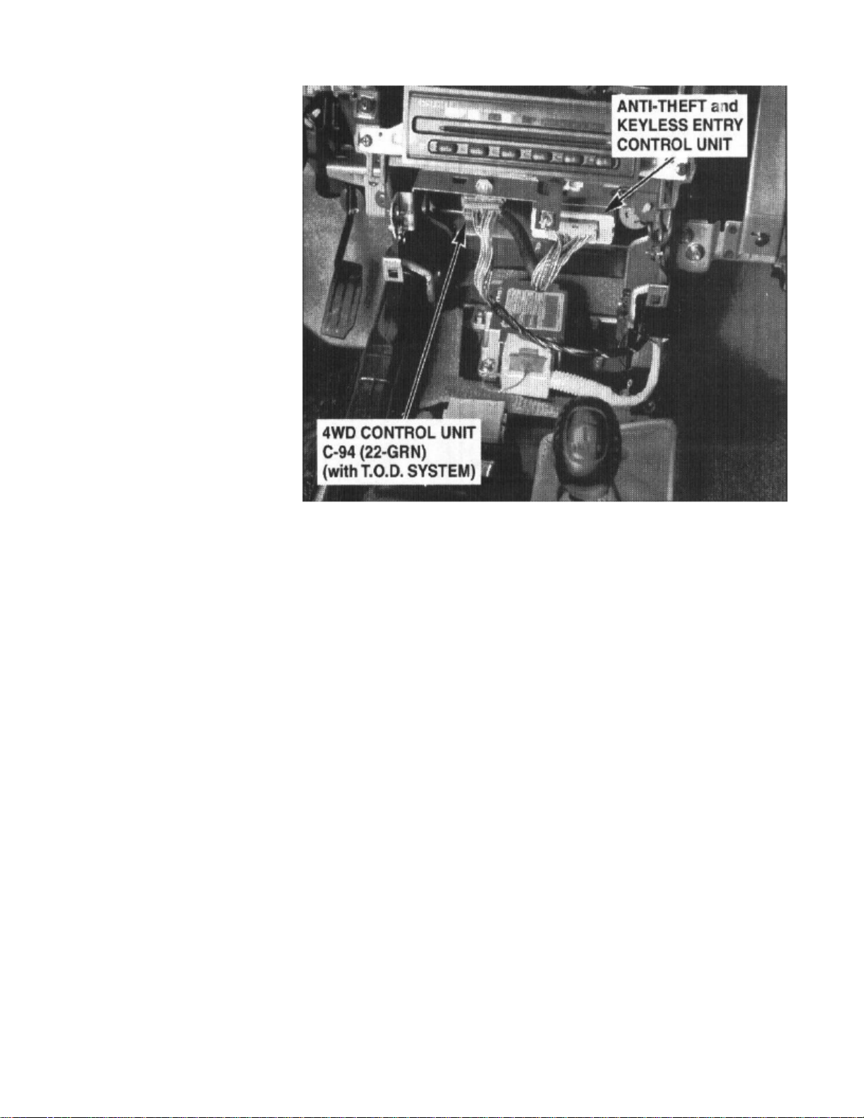
4. Disconnect the connector (2).5. Remove four screws to remove the anti-theft & keyless entry control unit with bracket (1).
Page 5

6. Remove two nuts from the anti-theft & keyless entry control unit with bracket (3) to remove the anti-theft & keyless entry controller (4).
INSTALLATION
To install, follow the removal steps in the reverse order.
Page 6

> Relays and Modules > Relays and Modules - Accessories and Optional Equipment > General Module > Component Information > Diagrams > Diagram Information and Instructions
General Module: Diagram Information and Instructions
How to Read Circuit Schematics
Circuit schematics break the entire electrical system into individual circuits. Electrical components that work together are shown together.
Each drawing is arranged so that current flows from positive at the top of the page, to ground, at the bottom of the page. The "hot" labels at the top of afuse show when the starter switch supplies power to that fuse.
Wires that connect to another circuit are shown with an arrowhead pointing in the direction of current flow. The name of the circuit that shares wiring isprovided for reference.
"See Dash Fuse Box" means that there are other connections to circuits that are not shown. These shared circuits are shown on the Dash Fuse Box circuitschematic. "See Ground Distribution" means that there are shared ground circuits which are shown on the Ground Distribution circuit schematic.
4-foot
No attempt is made on the schematic to represent components and wiring as they physically appear on the car. For example, a length of wire is nottreated any differently in a schematic than one which is only a few inches long. The number of cavities for each connector is listed in the ComponentLocation Index rather than being illustrated. Similarly, switches and other components are shown as simply as possible with regard to function only.
The example shows a horns schematic. Locate the horn schematic by using the Circuit Index. The circuit schematic will look similar to the one shown.The schematic is read from top to bottom.
Page 7

> Relays and Modules > Relays and Modules - Accessories and Optional Equipment > General Module > Component Information > Diagrams > Diagram Information and
Instructions > Page 12
Trooper S 2WD V6-3.5L (2001)
Voltage is applied to the horn relay at all times. When the relay coil is grounded by closing the horn switch, the relay contacts close. When the relaycontacts are closed, both the LH and RH horns are energized.
Lighting Switch Details Schematics
Page 8

The Lighting Switch Details schematic shows all the wiring between the light switch, light relays, and the components connected to the output of thelight switch and relays. The Lighting Switch Details schematic is helpful in locating a short circuit on the output side of the light switch and relays.
Component Locations
Page 9

> Relays and Modules > Relays and Modules - Accessories and Optional Equipment > General Module > Component Information > Diagrams > Diagram Information and
Instructions > Page 13
Trooper S 2WD V6-3.5L (2001)
A component location index follows each schematic. Except for the location of obvious components like left headlight, the index lists the location of
Page 10

every component, connector and ground in the schematic. The index also gives references to component location photographs located in/Locations/Photographs. See: Locations The number of cavities in each connector and the connector color is also listed. Wires may not be used in allconnector cavities.
Ground Distribution Schematics
The Ground Distribution schematics show which components share a ground point. This information can often be a time-saver when troubleshootingground circuits. For example, in the schematic, if both headlights and the park/turn light on one side are all out, you could suspect an open in theircommon ground wire or the ground connection itself. On the other hand, if one of the lights works, you know that the ground and the wire up to thesplice are good. You have learned this just by inspecting the schematic and knowing the vehicle's symptoms. No actual work on the lighting system isneeded.
Page 11

> Relays and Modules > Relays and Modules - Accessories and Optional Equipment > General Module > Component Information > Diagrams > Diagram Information and
Instructions > Page 14
Trooper S 2WD V6-3.5L (2001)
Power Distribution Schematics
Page 12

The Power Distribution schematic shows the wiring from the battery and generator to the starter solenoid, fuse box, starter switch and light switch. Thefirst component after a fusible link is also shown. In certain instances, the first component after a fuse box fuse and light switch is also shown.
The Power Distribution schematic refers to Dash Fuse Box and Lighting Switch Details schematics. By using these three (3) schematics, powerdistribution wiring can be followed from the battery and generator to the first component after a fusible link, fuse, and light switch. The ability to followthe power distribution wiring to the first component in each circuit is extremely helpful in locating short circuits which cause fusible links and fuses toopen.
The fuses in the schematic are "Hot At All Times," since battery voltage is always applied to them.
Dash Fuse Box Schematics
Page 13

> Relays and Modules > Relays and Modules - Accessories and Optional Equipment > General Module > Component Information > Diagrams > Diagram Information and
Instructions > Page 15
Trooper S 2WD V6-3.5L (2001)
Page 14

The Dash Fuse Box schematic shows all of the wiring between a fuse and the components connected to that fuse. The Dash Fuse Box schematic ishelpful in locating a short circuit that causes a fuse to open. This schematic may aid in troubleshooting an inoperative circuit by showing a second circuitthat uses the same fuse. If the second circuit works, then the fuse and certain wires of the inoperative circuit are good.
Page 15

> Relays and Modules > Relays and Modules - Accessories and Optional Equipment > General Module > Component Information > Diagrams > Diagram Information and
Instructions > Page 16
Trooper S 2WD V6-3.5L (2001)
Page 16

1 Of 3
Page 17

> Relays and Modules > Relays and Modules - Accessories and Optional Equipment > General Module > Component Information > Diagrams > Diagram Information and
Instructions > Page 17
Trooper S 2WD V6-3.5L (2001)
Page 18

2 Of 3
Page 19

> Relays and Modules > Relays and Modules - Accessories and Optional Equipment > General Module > Component Information > Diagrams > Diagram Information and
Instructions > Page 18
Trooper S 2WD V6-3.5L (2001)
Page 20

3 Of 3
Page 21

> Relays and Modules > Relays and Modules - Accessories and Optional Equipment > General Module > Component Information > Diagrams > Diagram Information and
Instructions > Page 19
Trooper S 2WD V6-3.5L (2001)
Page 22

Part 1 Of 5
Page 23

> Relays and Modules > Relays and Modules - Accessories and Optional Equipment > General Module > Component Information > Diagrams > Diagram Information and
Instructions > Page 20
Trooper S 2WD V6-3.5L (2001)
Page 24

Part 2 Of 5
Page 25

> Relays and Modules > Relays and Modules - Accessories and Optional Equipment > General Module > Component Information > Diagrams > Diagram Information and
Instructions > Page 21
Trooper S 2WD V6-3.5L (2001)
Page 26

Part 3 Of 5
Page 27

> Relays and Modules > Relays and Modules - Accessories and Optional Equipment > General Module > Component Information > Diagrams > Diagram Information and
Instructions > Page 22
Trooper S 2WD V6-3.5L (2001)
Page 28

Part 4 Of 5
Page 29

> Relays and Modules > Relays and Modules - Accessories and Optional Equipment > General Module > Component Information > Diagrams > Diagram Information and
Instructions > Page 23
Trooper S 2WD V6-3.5L (2001)
Page 30

Part 5 Of 5
Page 31

> Relays and Modules > Relays and Modules - Accessories and Optional Equipment > General Module > Component Information > Diagrams > Diagram Information and
Instructions > Page 24
Trooper S 2WD V6-3.5L (2001)
Page 32

Part 1 Of 5
Page 33

> Relays and Modules > Relays and Modules - Accessories and Optional Equipment > General Module > Component Information > Diagrams > Diagram Information and
Instructions > Page 25
Trooper S 2WD V6-3.5L (2001)
Page 34

Part 2 Of 5
Page 35

> Relays and Modules > Relays and Modules - Accessories and Optional Equipment > General Module > Component Information > Diagrams > Diagram Information and
Instructions > Page 26
Trooper S 2WD V6-3.5L (2001)
Page 36

Part 3 Of 5
Page 37

> Relays and Modules > Relays and Modules - Accessories and Optional Equipment > General Module > Component Information > Diagrams > Diagram Information and
Instructions > Page 27
Trooper S 2WD V6-3.5L (2001)
Page 38

Part 4 Of 5
Page 39

> Relays and Modules > Relays and Modules - Accessories and Optional Equipment > General Module > Component Information > Diagrams > Diagram Information and
Instructions > Page 28
Trooper S 2WD V6-3.5L (2001)
Page 40

Page 41

Part 5 Of 5
Page 42

> Relays and Modules > Relays and Modules - Accessories and Optional Equipment > General Module > Component Information > Diagrams > Diagram Information and Instructions > Page 29
General Module: Diagnostic Aids
Voltmeter and Test Light
Use a voltmeter or test light to check for voltage. While a test light shows whether or not voltage is present, a voltmeter indicates how much voltage thereis.
CAUTION: 10-megohms
A number of circuits include solid state devices. Voltages in these circuits should be tested only with a or higher impedancedigital multimeter. Never use a test light on circuits that contain solid-state devices. Damage to the device may result.
12-volts
On circuits without solid-state devices, a test light may be used to check for voltage. A test light is made up of a bulb with a pair of leadsattached. After grounding one lead, touch the other lead to various points along the circuit where voltage should be present. The bulb will go on if thevoltage at the point being tested is greater than .5 volts
Self-Powered Test Light and Ohmmeter
Use a self-powered test light or ohmmeter to check for continuity. The ohmmeter shows how much resistance there is between two points along a circuit.Low resistance means good continuity.
Never use a self-powered test light on circuits that contain solid-state devices. Damage to these devices may result.CAUTION:
Diodes and solid-state devices in a circuit can make an ohmmeter give a false reading. To find out if a component is affecting a measurement, take onereading, reverse the leads, and take a second reading. If the readings differ, the component is affecting the measurement.
Circuits that contain solid-state devices should only be tested with a or higher impedance digital multimeter.10-megaohm
A self-powered test light consists of a light bulb, battery and two leads. If the leads are touched together, the bulb will go on.
Fused Jumper Wire
Page 43

> Relays and Modules > Relays and Modules - Accessories and Optional Equipment > General Module > Component Information > Diagrams > Diagram Information and
Instructions > Page 30
Trooper S 2WD V6-3.5L (2001)
A self-powered test light is only used on an un-powered circuit. First disconnect the battery or remove the fuse that feeds the circuit you are working on.Select two points along the circuit through which there should have continuity. Connect one lead of the self-powered test light to each point. If there iscontinuity, the test light's circuit will be completed and the bulb will go on.
Use a jumper wire to bypass an open circuit. A jumper wire is made up of an in-line fuse holder connected to a set of test leads. It should have a fiveampere fuse. Never use a jumper wire across any load. This direct battery short will blow the fuse.
Short Finder
Short finders are available to locate shorts to ground. The short finder creates a pulsing magnetic field in the shorted circuit and shows you the locationof the short through body trim or sheet metal. Its use is explained in the troubleshooting tests.
Testing For Voltage
Page 44

This test measures voltage in a circuit. When testing for voltage at a connector, you may not have to separate the two halves of the connector. Instead,probe the connector from the back. Always check both sides of the connector because dirt and corrosion between its contact surfaces can cause electricalproblems.
1. Connect one lead of test light to known good ground, or if you are using a voltmeter, be sure you connect its negative lead to ground.2. Connect the other lead of the test light or voltmeter to the point you want to check.3. If the test light glows, there is voltage present. If you are using a voltmeter, note the voltage reading. It should be within of measuredone volt
battery voltage. A loss of more than indicates a problem.one volt
Testing For Continuity
Page 45

> Relays and Modules > Relays and Modules - Accessories and Optional Equipment > General Module > Component Information > Diagrams > Diagram Information and
Instructions > Page 31
Trooper S 2WD V6-3.5L (2001)
This test checks for continuity within a circuit. When testing for continuity at a connector, you may not have to separate the two halves of the connector.Instead, probe the connector from the back. Always check both sides of the connector because dirt and corrosion between contact surfaces can causeelectrical problems.
zero ohms
1. Disconnect the negative cable from the car battery.2. If you are using an ohmmeter, hold the leads together and adjust the ohmmeter to read .3. Connect one lead of self-powered test light or ohmmeter to one end of the part of the circuit you wish to test.4. Connect the other lead to the other end.5. If the self-powered test light glows, there is continuity. If you're using an ohmmeter, low or no resistance means good continuity.
Testing For A Voltage Drop
Page 46

This test checks for voltage drop along a wire, or through a connection or switch.
1. Connect the positive lead of a voltmeter to the end of the wire (or to the side of the connector or switch) closest to the battery.2. Connect the negative lead to the other end of the wire (or the other side of the connector or switch).3. Operate the circuit.4. The voltmeter will show the difference in voltage between the two points. A difference, or drop of more than may indicate a problem.0.5 volts
Check the circuit for loose or dirty connections.
Testing For Short to Ground With Test Light or Voltmeter
Page 47

> Relays and Modules > Relays and Modules - Accessories and Optional Equipment > General Module > Component Information > Diagrams > Diagram Information and
Instructions > Page 32
Trooper S 2WD V6-3.5L (2001)
1. Remove the blown fuse and disconnect the load.2. Connect a test light or voltmeter across the fuse terminals. Make sure voltage is being applied to the battery side fuse terminal. Check schematic to
see if the ignition switch needs to be in RUN.
3. Beginning near the fuse box, wiggle the harness. Continue this at convenient points about apart while watching the test light orsix inches
voltmeter.
4. When the test light blinks or the voltmeter needle moves, there is a short to ground in the wiring near that point.
Testing For A Short With A Self-Powered Test Light or Ohmmeter
Page 48
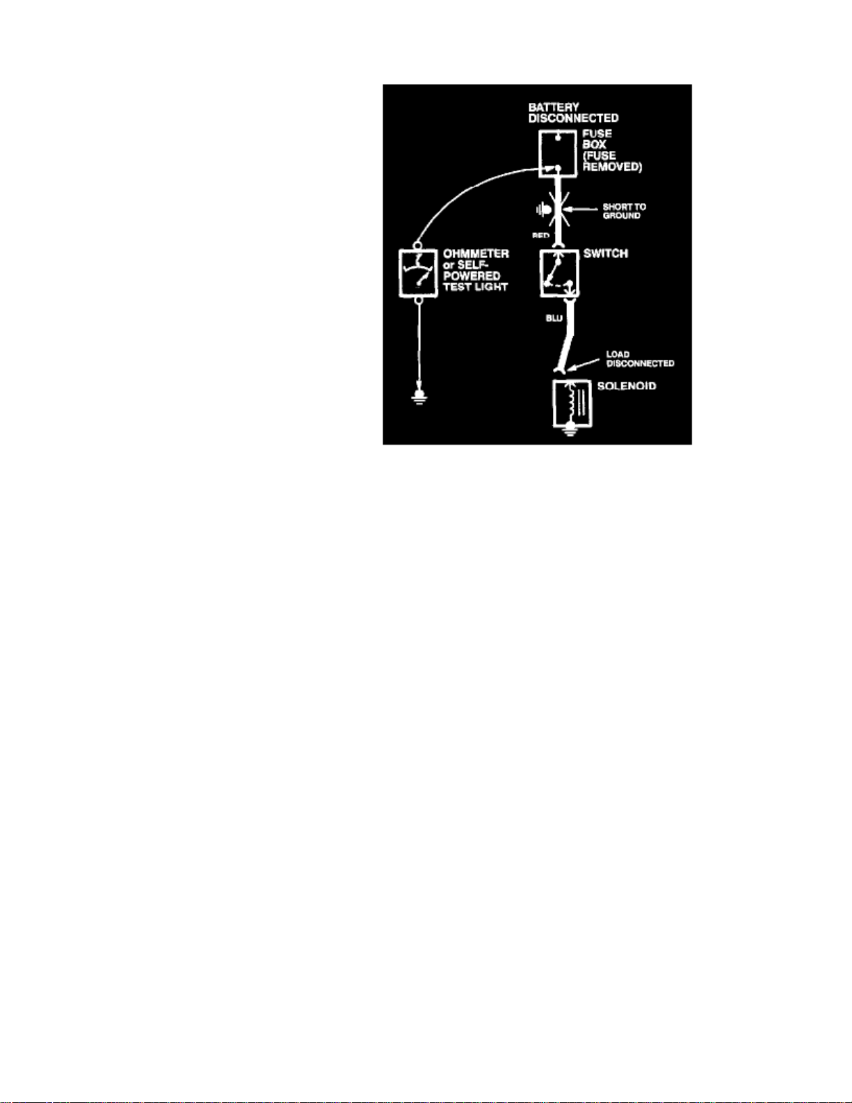
1. Remove the blown fuse and disconnect the battery and load.2. Connect one lead of a self-powered test light or ohmmeter to the fuse terminal load side.3. Connect the other lead to a known good ground.4. Beginning near the fuse box, wiggle the harness. Continue this at convenient points about apart while watching the test light orsix inches
ohmmeter.
5. If the self-powered test light blinks or the ohmmeter needle moves, there is a short to ground in the wiring near that point.
Testing For A Short to Ground With A Short Finder
Page 49

> Relays and Modules > Relays and Modules - Accessories and Optional Equipment > General Module > Component Information > Diagrams > Diagram Information and
Instructions > Page 33
Trooper S 2WD V6-3.5L (2001)
Page 50

1. With the battery connected, remove the blown fuse.2. Connect the short finder between the positive battery terminal and the load side fuse terminal.3. Close all switches in series with the wire that you are troubleshooting.4. Turn on the short finder This will send pulses of current to the short and create a pulsing magnetic field around the wiring between the fuse box
and the short.
5. Beginning at the fuse box, slowly move the short finder meter along the circuit wiring. The meter will show current pulses through sheet metal and
body trim. As long as the meter is between the fuse and the short, the needle will move with each current pulse. Once you move the meter past thepoint of the short, the needle will stop moving. Check around this area to locate the cause of the short circuit.
Page 51

Page 52

> Relays and Modules > Relays and Modules - Accessories and Optional Equipment > General Module > Component Information > Diagrams > Diagram Information and Instructions > Page 34
General Module: Electrical Diagrams
Page 53

> Relays and Modules > Relays and Modules - Accessories and Optional Equipment > General Module > Component Information > Diagrams > Diagram Information and
Instructions > Page 35
Trooper S 2WD V6-3.5L (2001)
Alarm & Relay Controls (1 Of 3) Image 70
Page 54

Alarm & Relay Controls (2 Of 3) Image 70-1
Page 55

> Relays and Modules > Relays and Modules - Accessories and Optional Equipment > General Module > Component Information > Diagrams > Diagram Information and
Instructions > Page 36
Trooper S 2WD V6-3.5L (2001)
Page 56

Alarm & Relay Controls (3 Of 3) Image 70-2
Page 57

Page 58

> Relays and Modules > Relays and Modules - Accessories and Optional Equipment > General Module > Component Information > Diagrams > Page 37
General Module: Description and Operation
The alarm and relay control unit controls the Key-in ignition warning, seat belt warning, windshield wiper/washer system, rear wiper/washer system,doors open, dome light, and the rear defogger.
Page 59

Page 60

> Relays and Modules > Relays and Modules - Accessories and Optional Equipment > General Module > Component Information > Diagrams > Page 38
General Module: Service and Repair
REMOVAL
1. Disconnect the battery ground cable.2. Remove the glove box.3. Remove the instrument panel passenger lower cover assembly.4. Remove the passenger Knee bolster reinforcement assembly.
5. Remove the fixing bolts, disconnect the connectors and then remove the alarm & relay control unit (1).
INSTALLATION
To install, follow the removal steps in the reverse order.
Page 61

Page 62
> Relays and Modules > Relays and Modules - Accessories and Optional Equipment > Keyless Entry Module > Component Information > Locations
62 - Behind Front Console
Page 63

Page 64

> Relays and Modules > Relays and Modules - Accessories and Optional Equipment > Keyless Entry Module > Component Information > Locations > Page 42
Keyless Entry Module: Service and Repair
1. Remove and install the control unit.
- Refer to Keyless Entry Module / Removal and Installation. See:
2. Register ID code in Keyless Entry / Service and Repair.
-
Refer to ID Code Registration in Keyless Entry / Service and Repair. See: Accessories and Optional Equipment/Antitheft and AlarmSystems/Keyless Entry/Service and Repair
3. Check that the keyless entry system works normally.
Page 65

Page 66

> Relays and Modules > Relays and Modules - Body and Frame > Keyless Entry Module > Component Information > Locations
62 - Behind Front Console
Page 67

Page 68

> Relays and Modules > Relays and Modules - Body and Frame > Keyless Entry Module > Component Information > Locations > Page 47
Keyless Entry Module: Service and Repair
1. Remove and install the control unit.
- Refer to Keyless Entry Module / Removal and Installation. See:
2. Register ID code in Keyless Entry / Service and Repair.
-
Refer to ID Code Registration in Keyless Entry / Service and Repair. See: Accessories and Optional Equipment/Antitheft and AlarmSystems/Keyless Entry/Service and Repair
3. Check that the keyless entry system works normally.
Page 69

Page 70

> Relays and Modules > Relays and Modules - Brakes and Traction Control > Electronic Brake Control Module > Component Information > Locations
Page 71

Page 72

> Relays and Modules > Relays and Modules - Brakes and Traction Control > Electronic Brake Control Module > Component Information > Locations > Page 52
Page 73

Page 74

> Relays and Modules > Relays and Modules - Brakes and Traction Control > Electronic Brake Control Module > Component Information > Locations > Page 53
Electronic Brake Control Module: Service Precautions
Computer System Service Precautions
(EHCU)
The Anti-lock Brake System interfaces directly with the Electronic Hydraulic Control Unit which is a control computer that is similar insome regards to the Powertrain Control Module. These modules are designed to withstand normal current draws associated with vehicle operation.However, care must be taken to avoid overloading any of the EHCU circuits. In testing for opens or shorts, do not ground or apply voltage to any ofthe circuits unless instructed to do so by the appropriate diagnostic procedure. These circuits should only be tested with a high impedance multimeter(J-39200) or special tools. Power should never be removed or applied to any control module with the ignition in the "ON" position.Before removing or connecting battery cables, fuses or connectors, always turn the ignition switch to the "OFF" position.
Page 75

Page 76

> Relays and Modules > Relays and Modules - Brakes and Traction Control > Electronic Brake Control Module > Component Information > Locations > Page 54
Electronic Brake Control Module: Description and Operation
Electronic Hydraulic Control Unit (EHCU)
The EHCU consists of ABS control circuits, fault detector, and a fail-safe. It drives the hydraulic unit according to the signal from each sensor,canceling ABS to return to normal braking when a malfunction has occurred in the ABS.The EHCU has a self-diagnosing function which can indicate faulty circuits during diagnosis.The EHCU is mounted on the engine compartment front right side. It consists of a Motor, Plunger Pump, Solenoid Valves and Check Valve.On the outside, the relay box containing a motor relay and a valve relay is installed.
Solenoid Valves:
Reservoir:
Plunger Pump:
Motor:
Reduces or holds the caliper fluid pressure for each front disc brake or both rear disc brakes according to the signal sent from theEHCU. Temporarily holds the brake fluid that returns from the front and rear disc brake caliper so that pressure of front disc brake caliper can bereduced smoothly. Feeds the brake fluid held in the reservoir to the master cylinder. Drives the pump according to the signal from EHCU. Controls the brake fluid flow.Check Valve:
Page 77

Page 78
> Relays and Modules > Relays and Modules - Brakes and Traction Control > Electronic Brake Control Module > Component Information > Locations > Page 55
Electronic Brake Control Module: Service and Repair
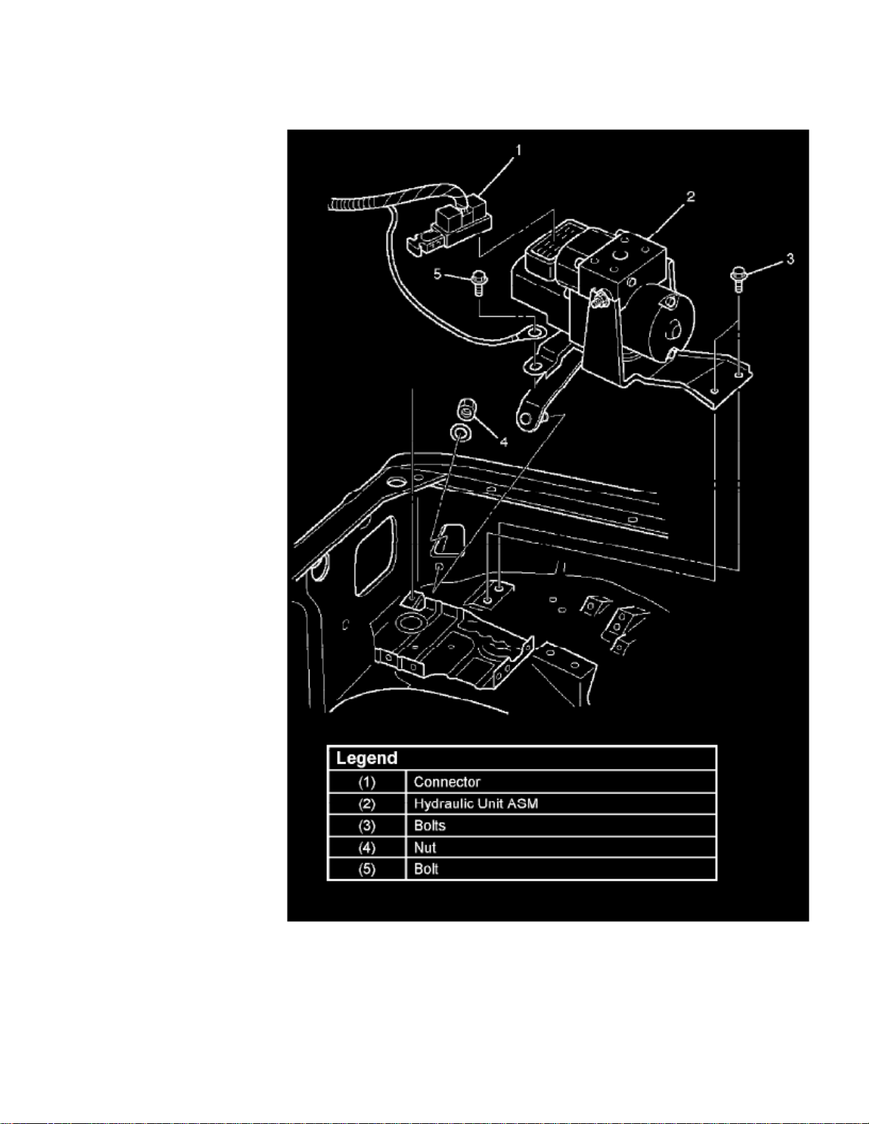
Removal
1. Remove battery ASM.2. Remove harness connector.3. Remove EHCU fixing nuts.4. Remove brake pipes.
- After disconnecting brake pipe, cap or tape the openings of the brake pipe to prevent the entry of foreign matter.
Page 79

5. Remove hydraulic unit fixing nuts.
Installation
To install, follow the removal steps in the reverse order, noting the following points:-
22 Nm (16 ft. lbs.)
TorqueHydraulic unit fixing nuts: Ground cable: Brake pipe (joint bolts): 14 Nm (10 ft. lbs.) 16 Nm (12 ft. lbs.)
- After installing the hydraulic unit, bleed brakes completely.
Page 80

> Relays and Modules > Relays and Modules - HVAC > Compressor Clutch Relay > Component Information > Locations
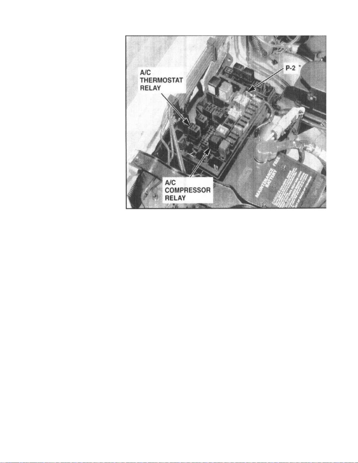
36 - Fuse/Relay Box (Cover Removed)
Page 81

Page 82

> Relays and Modules > Relays and Modules - HVAC > Compressor Clutch Relay > Component Information > Testing and Inspection > A/C Clutch Relay
Compressor Clutch Relay: Testing and InspectionA/C Clutch Relay
Relays Test
This test is conducted to check Fuel Pump Relay and A/C Clutch for proper operation.
Tech 2 must be used for this test.
Test Procedure:
1. Connect Tech 2 to the vehicle DLC.2. Ignition SW is "On".
3. Select F3: Miscellaneous Test in the Application Menu.
4. Select F1 : Relay Test in the Miscellaneous Test.
Page 83

> Relays and Modules > Relays and Modules - HVAC > Compressor Clutch Relay > Component Information > Testing and Inspection > A/C Clutch Relay > Page 62
Trooper S 2WD V6-3.5L (2001)
Page 84

5. Select F0: Fuel Pump Relay.
6. Push "On" soft key.7. Control Fuel Pump Relay and check data list.
- If the data list changes, the Fuel Pump Relay is normal.
8. Select F1 : A/C Clutch Relay.9. Run the Engine at idle.
Page 85

10. Turn on Air Conditioning.11. Turn "On" and "Off" A/C Switch.12. Control A/C Clutch Relay and check data list.
- If the data list changes, the Fuel Pump Relay is normal.
Page 86

> Relays and Modules > Relays and Modules - HVAC > Compressor Clutch Relay > Component Information > Testing and Inspection > A/C Clutch Relay > Page 63
Compressor Clutch Relay: Testing and InspectionHeater, A/C, Thermostat and Compressor Relay
Heater and A/C (B-36), Thermostat (X-5) and Compressor (X-7) Relay
1. Disconnect relays and check for continuity and resistance between relay terminals.
- For handling of these relays, refer to Heater & A/C Relay.
Page 87

Page 88

> Relays and Modules > Relays and Modules - HVAC > Compressor Clutch Relay > Component Information > Testing and Inspection > Page 64
Compressor Clutch Relay: Service and Repair
Removal Procedure
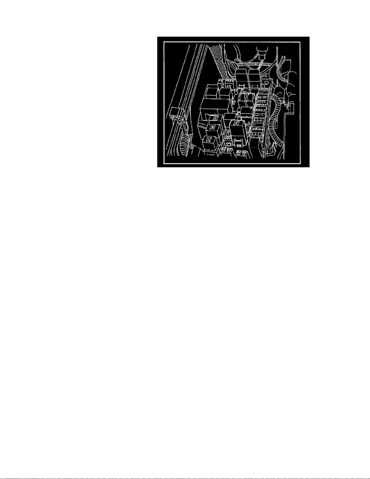
1. Remove the fuse and relay box cover from under the hood.2. Consult the diagram on the cover to determine which is the correct relay.3. Insert a small screwdriver into the catch slot on the forward side of the fuel pump relay.
4. The screwdriver blade will release the catch inside.
Page 89

> Relays and Modules > Relays and Modules - HVAC > Compressor Clutch Relay > Component Information > Testing and Inspection > Page 65
Trooper S 2WD V6-3.5L (2001)
5. Pull the relay straight up and out of the fuse and relay box.
Installation Procedure
1. Insert the relay into the correct place in the fuse and relay box with the catch slot facing forward.2. Press down until the catch engages.
- An audible "click" will be heard.
Page 90
3. Install the fuse and relay box cover.
Page 91

Page 92

> Relays and Modules > Relays and Modules - HVAC > Control Module HVAC > Component Information > Locations
64 - Center Of Dash
Page 93

Page 94
> Relays and Modules > Relays and Modules - HVAC > System Relay, HVAC > Component Information > Locations
36 - Fuse/Relay Box (Cover Removed)
Page 95

Page 96

> Relays and Modules > Relays and Modules - HVAC > System Relay, HVAC > Component Information > Locations > Page 72
System Relay: Testing and Inspection
Heater and A/C (B-36), Thermostat (X-5) and Compressor (X-7) Relay
1. Disconnect relays and check for continuity and resistance between relay terminals.
- For handling of these relays, refer to Heater & A/C Relay.
Page 97

Page 98

> Relays and Modules > Relays and Modules - HVAC > System Relay, HVAC > Component Information > Locations > Page 73
System Relay: Service and Repair
1. Disconnect the heater and the A/C relay (B-36).
- When removing the connector for relay, unfasten the tang lock of the connector by using a screwdriver, then pull the relay (1) out.
2. Check for continuity between the heater and the A/C relay (B-36) terminals.
Page 99

Page 100

> Relays and Modules > Relays and Modules - Instrument Panel > A/T Shift Indicator Module > Component Information > Locations
74 - Behind Lower Left Dash Panel
 Loading...