

istobal Twash 4TA6000 Civil Work And Installation

WASH TUNNEL
MOD. 4TA6000
Departamento de Formación V_07_14
TRANSLATED FROM THE ORIGINAL MANUAL
CIVIL WORK AND INSTALLATION
34GJ100B
ISTOBAL, S.A. Avda. Conde del Serrallo, 10 46250 L’Alcúdia (Valencia - España)
Teléfono 96 299 79 40 Fax 96 299 79 91 E-mail: istobal@istobal.com www.istobal.com
GB
1
34GJ100B
1. SAFETY 3
2. BUILDING SPECIFICATIONS 7
3. EXCAVATION PLAN 12
4. NO ENCLOSURE 14
1
INDEX
2.1. Excavation work 7
2.2. Filling work and embankment 7
2.3. Bed 7
2.4. Reinforced concrete slab 8
2.5. Concrete specifications 9
2.6. Drainage gutters 10
2.7. Drainage piping 11
2.8. Rain gutters, with enclosure 11
3.1. No enclosure 12
3.2. With enclosure 13
4.1. Design measurements and sections 14
4.2. Electrical lines 16
4.3. Air and water lines 17
4.4. Dimensions 18
5. WITH ENCLOSURE MP 20
5.1. Design measurements and sections 20
5.2. Dimensions 22
5.3. Electrical lines 24
5.4. Air and water lines 25
6. WITH ENCLOSURE CM 26
6.1. Design measurements and sections 26
6.1. Adjoining bays 28
6.2. Dimensions 30
6.1. Electrical lines 32
6.1. Air and water lines 33
7. CONNECTION DETAILS 34
8. INSTALLATION 36
8.1. Service lines and pipes 36
8.2. Electrical data 38
8.3. Electrical distribution cabinet 39
GB
2

1
SAFE PRACTICE AND SAFETY RULES
To guarantee your safety, please cooperate with the company at all times and obey the safety rules detailed here
to help ensure that accidents are avoided. (Article 29. Safety at Work Act). The following list of obligations shall
be respected by all workers carrying out work whether directly employed by ISTOBAL or subcontracted.
SAFETY
• Please make proper use of the personal protection equipment provided.
• Follow the instructions of your superiors, and any indications given by the person responsible for the
facility.
• Keep tools and personal and collective protection equipment in good order. If you observe any deterioration
in them, advise your superior immediately.
• Keep the work site clean and tidy.
• Advise your superiors and colleagues of any danger or risk that you perceive on the facility. In case of
serious and imminent risk, do as indicated above while also ceasing to perform any activity which may add
to such risk.
PREVENTIVE MEASURES
ISTOBAL, S.A. personnel and workers subcontracted by the company are to take into account the following
preventive measures while carrying out work:
• Hand-held ladders are not permitted for performing jobs. For work where use of a scaffold is not physically
possible or where its use would be an added risk, a platform step ladder is to be used.
• If a certied scaffold is used, follow the manufacturer's assembly instructions closely. Make sure it is in
perfect condition before use. Do not place it near power lines. If the scaffold is moveable, put the brakes on
all the wheels and use securing bars to stop it moving unexpectedly. Do not move the scaffold with workers
on it. Do not leave tools or materials lying around on the scaffold.
• If a platform step ladder is used, it must only be used by duly trained and authorised personnel. Make sure
that it is used in accordance with the instructions supplied with it.
• All waste generated is to be collected and removed from the work area as and when it is generated. The
work area should be kept as clean as possible at all times.
• Make sure the work area is organised - do not leave materials and tools lying around as these could cause
accidents.
• When materials are being loaded and unloaded with winches / cranes; materials are being lifted; heavy parts
are being mounted, etc., make sure there are no workers underneath. Check this before starting to move
anything.
CONDUCT ON SITE
• Station your vehicle in designated parking zones. Turn off the engine. Parking is not permitted in classied
areas or where the vehicle would obstruct the passage of persons or vehicles.
• Inform the supervisor or person responsible for the facility of the presence of the vehicle and why it is
there.
CIVIL WORK AND INSTALLATION
• Before starting work, put up signs and cordon off the areas where you will be setting up equipment such as
winches, compressors, etc.
• After the work is completed, remove leftover waste from the work area, such as plastic, cardboard, wood,
etc.
• Collect your tools and other equipment.
• Inform the Supervisor or person responsible for the facility that the work is completed and what the situation
is now.
GB
3
SAFETY
PROTECTION EQUIPMENT
Personal and collective protection equipment used should be appropriate to the task, certied with the mark,
and display the corresponding inspection dates.
Personal protection equipment should give effective protection against the risks they are intended for. Such
equipment should not constitute a risk in itself nor cause unnecessary inconvenience. The equipment should:
• Respond to the conditions existing in the workplace.
• Take into account the anatomy, physiology, and state of health of the operator.
• Fit the bearer properly after the pertinent adjustments.
• Where multiple risks are involved which require several types of personal protection equipment to be
used together, they should be mutually compatible and maintain their level of efciency in relation to the
corresponding risk or risks.
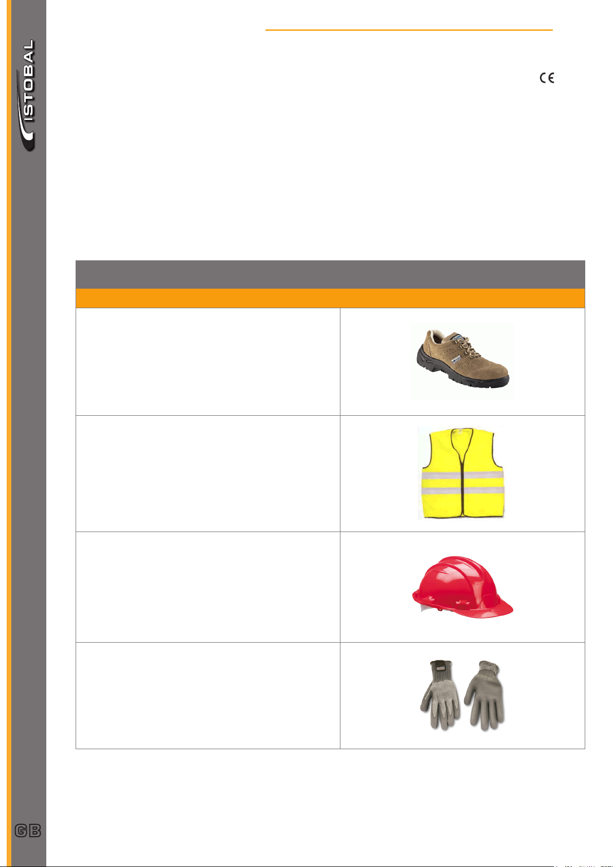
PERSONAL PROTECTION EQUIPMENT
COMPULSORY PROTECTION
1
Safety footwear.
Mechanical protection, waterproof, and with a dielectric
sole, anti-slip, and anti-perforation protection.
High visibility reective vest.
Safety helmet.
GB
4
Safety gloves.
1
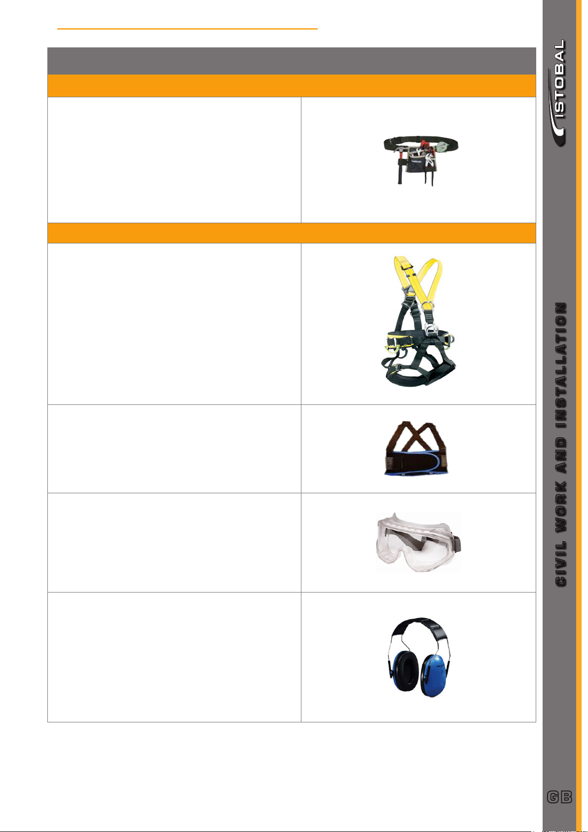
PERSONAL PROTECTION EQUIPMENT
OTHER PROTECTION DEPENDING ON THE WORK TO BE DONE
Tool belt.
OTHER PROTECTION DEPENDING ON THE WORK TO BE DONE
SAFETY
Safety harness.
For work at a height of 2 m. and above.
Back support belt.
For tasks which require unusual positions to be adopted, or straining.
High impact safety goggles.
Use of drills, radial saws, etc.
CIVIL WORK AND INSTALLATION
Ear protection.
Use of drills, radial saws, etc.
GB
5
SAFETY
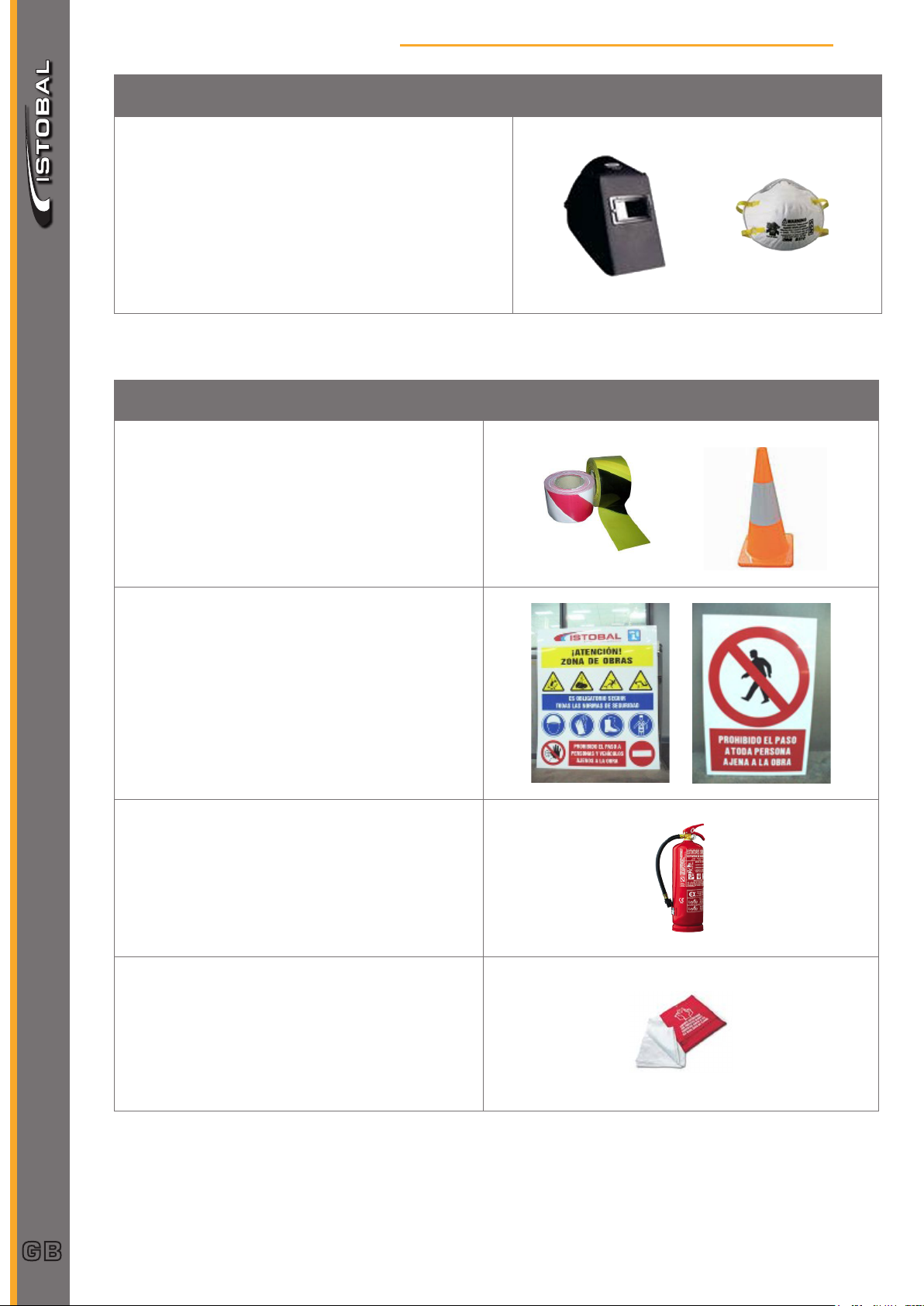
PERSONAL PROTECTION EQUIPMENT
Welding screens and masks with metal smoke lter.
Use of welding sets.
COLLECTIVE PROTECTION EQUIPMENT
1
Safety tape and cones
To indicate and cordon off the work area.
No entry sign.
To prevent unauthorized access, and indicate the
need for PPE to be worn.
Portable re extinguisher.
GB
6
Fire blankets
For work generating heat (welding, radial saws,
etc.).

2
BUILDING SPECIFICATIONS
2.1. Excavation work
Any vegetation will be cleared, and any elements or small infrastructures will be removed, should there be any.
The whole site will be cleared and the vegetation soil all over it will be removed.
Once the desired level has been reached, soil moisture and compaction will be checked.
2.2. Filling work and embankment
'Esplanade' or 'embankment' is the nished excavated area where the paving layers (bed and slab) will be
built.
The esplanade must be correctly compacted until it is totally even and homogeneous, which requires a number
of roller operations.
• Minimum esplanade type E1 (5 < CBR < 10)
If the esplanade needs to be formed or if the features of the existing plot are not suitable, these can be either
improved by means of stabilization, or replaced at an adequate depth by a bed with the right features.
• Materials to be used Features:
- Minimum: Adequate ground (as per PPTG PG3)
- Stones with max. diameter below 10 cm. Sieved with
sieve no. 200, 35% of weight.
- LL < 40
- Maximum density, normal Proctor test, 1.75 kg/dm3,
CBR>5
- Organic matter < 1%
- Soluble salts (including gypsum) < 0.2%
In the esplanade work and the subsequent bed, please bear in mind that the work to be done shall cover an
additional 3.0 m band parallel to the boundaries of the wash tunnel area so as to allow for drainage and for a
transition between the facility level and that of the adjoining areas.
2.3. Bed
Granular material layer between the esplanade and the slab, consisting of natural aggregates or aggregates
derived from quarry stone grinding or natural gravel, or clay/marl-free selected soils.
CIVIL WORK AND INSTALLATION
To be compacted in a single layer (15 cm course minimum) until 97% PM is reached.
• Type - Wet-mix macadam
• Thickness - See civil works ground plan.
GB
7

BUILDING SPECIFICATIONS
• Granulometry - Fractions going through the 0.08 sieve will be smaller than
• Compacted density - Over 100% of maximum density. Modied Proctor Test
2.4. Reinforced concrete slab
2
half the fractions sieved with the 0.40 sieve. Measured by
weight.
- Maximum aggregate size will be smaller than half the
compacted layer.
- The fraction retained by Sieve 5 should at least have 50%
(weight) elements with two or more fracture surfaces.
- Abrasion measured by Los Angeles test should be lower
than A 30.
- The material must be non-plastic and the sand-content
equivalent must be over A 35.
- CBR > 80 for 100% compaction, Modied Proctor Test
density, even in singular project areas (edges, meeting
points, elements).
• Thickness - See civil works ground plan.
• Reinforcement - Electro-welded mesh AEH 500 (fyk=5100 Kp/cm2)
• Slopes - See civil works ground plan.
• Contraction joints - every 5.0 m
- width 4 mm
- depth 40 mm
• Expansion joints - every 25.0 m
- width 20 mm
- lled and sealed
• Finishing process - Spreading and compacting with concrete screeder.
- Surface smoothing by screeder.
GB
8
- Mechanical oating once concrete is resistant enough
(helicopter, xed at propeller).
- Repeat previous operations as many times as necessary
until the desired nish is obtained. In our case, surface
nish must be non-slip.
- Curing by wax-based curing liquid (Bettocure-C).

2
BUILDING SPECIFICATIONS
2.5. Concrete specications
The slab concrete's corrosion exposure class is “IIa” (normal reinforcement for high moisture conditions). It is
adequate for areas that are not by the sea. For other types of exposure, check regulations in force.
Concerning exposure relating to concrete degradation phenomena other than corrosion, the concrete is ero-
sion-classed, “E”.
If the area were affected by frost, no melting salts would be needed for the foreseen purpose. Designation
would be “H” (frost exposure, no salt de-icing).
• Denition - with compression HM-30 / B / 20 / IIa+E
- with frost risk: HM-30 / B / 20 / E+H
• Water/cement rate
- (Table 37.3.2.a EHE-08)
- Below 0.50 (Exposure class E)
• Minimum concrete strength - (Table 37.3.2.b EHE-08)
- 30 N/mm2
• Cement - Portland cement EN 197-1 CEM I 32.5 N (APPENDIX
4. Tables A.4.2 and A.4.5 CE Marking EHE-08
and Appendix I RD 956/2008 RC-08)
- (Table 37.3.2.a EHE-08)
- Minimum content 325 kg/m3. (Do not exceed maximum
cement content 375kg/m3.
• Consistency - Concrete slump test, base 6 to 9 cm.
- (Art. 31.5 EHE-08) Consistency SOFT
CIVIL WORK AND INSTALLATION
• Coating - (Art. 37.2.4.1 EHE-08)
- Without blinding concrete, minimum nominal coating
80 mm.
- With blinding concrete, nominal coating 4mm.
• Curing - (Art. 37.3.7 EHE-08)
- Prolonged curing, at least 50% above normal, that is,
10 days approximately in normal conditions.
GB
9

BUILDING SPECIFICATIONS
• Aggregates - (Art. 37.3.7 EHE-08)
• Additives - Waterproong liquid (Sika-1), 3% of cement weight.
2
- Fine aggregates will be QUARTZ or a material with at
least the same hardness.
- Los Angeles coefcient for thick aggregates under 30.
- (Table 28.4.1.a. EHE-08)
- Thick aggregates: maximum % passing through sieve
0.063: 1.5 %.
- Fine aggregates: maximum % passing through sieve
0.063: 6 %.
- In case of frost risk (exposure class “F”), minimum
occluded air content 4.5%, as per UNE-EN 12350-7.
• Waterproong - (Art. 37.3.3 EHE-08)
- Concrete waterproong must be tested according to
UNE EN 12390-8, since the environmental exposure
class is “E”.
2.6. Drainage gutters
To be made on site using concrete with the same specications as the slab concrete and tting a prefabricated
PVC drainage gutter.
The gutters must be covered with perforated steel sheets seated on a 12 mm continuous prole on the gutter
edge.
• Width - 24 cm minimum.
• Depth - 19 cm minimum.
GB
10
• Slope - inner slope 1.0 % (minimum)
• Reinforcement - See civil works ground plan.
• Cover - Perforated steel sheet, thickness = 8 mm
- Dimensions: depending on gutter type (see details).

2
BUILDING SPECIFICATIONS
2.7. Drainage piping
Gutter and central trap drainage is via a number of pipes that run along the boundaries of the wash tunnel.
The pipes are PVC, with connection boxes and pits at intersection points where necessary.
The pipework facilitates the drainage of water coming from the wash tunnel, taking it to the sludge settler,
where water treatment starts for water to be recycled and reused in new wash processes.
• Pipes - PVC 160 mm minimum diameter
• Slope - minimum 1.0%
• Connection pits - Perforated bricks, rendered and smoothed.
2.8. Rain gutters, with enclosure
Rain water is collected and channelled by separate gutters that run parallel to the drainage piping. As in the
previous case, the pipes are arranged on the sides of the wash tunnel.
For wash tunnels without an enclosure, rain water is collected together with that of the actual tunnel.
All pipes must be PVC, even the special parts.
Pipe slope should not be under 1.0%. Pipes must lean on a concrete or sand bed.
Couplings as per drawings, in connection boxes or pits built with bricks, rendered and smoothed. Pit dimensions are indicated in the corresponding drawings.
CIVIL WORK AND INSTALLATION
GB
11
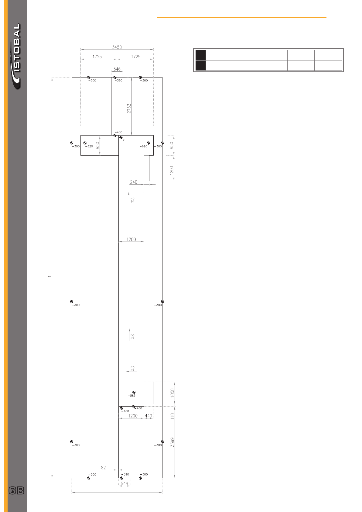
EXCAVATION PLAN
3.1. No enclosure
3
L1 15640 17360 18990 20610
Z 755 790 820 855
22240
885
GB
12
Measurements in mm.
 Loading...