

Page 1
FLOWMETER
415 Hope Avenue, PO Box 618, Roselle, NJ 07203
ENGINEERING MANUAL
1800 SERIES
FLOW MEASUREMENT & CONTROL SOLUTIONS
Phone: (908) 241-8880 Fax: (908) 241-7288 www.istec-corp.com
Page 2

PRODUCT OVERVIEW
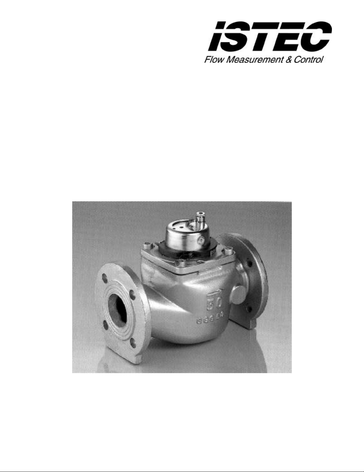
ISTEC’s “Super-Jet” 1800 Series are industrial grade water meters available in ½” through 12” sizes.
All sizes incorporate a variety of standard features such as U.S. gallon register, hermetically sealed nonresettable counter, trickle flow indicator and pulse output. ISTEC “Super-Jet” design leaves only the
turbine immersed, resulting in reliable and long lasting performance.
For easy installation, all ISTEC flow meters up to 1½’’ are available with union connections; 2’’ and
larger sizes are designed with standard flanges. The smooth running turbine, together with a selfaligning suspension bearing system and other innovative features provides superior reliability and
accuracy that meets or exceeds AWWA standards.
In addition, a high temperature version (350ºF) of the 2”, 3” and 4” meters is available.
COMPONENT DESCRIPTION
BODY
Pipe Size ½” (15mm) To 1½” (40mm) Brass
Pipes Size 2” (50mm) To 12” (300mm) Cast Iron
FLOW INSERT
Turbine Fiberglass
Turbine Axle Chrome/Nickel/Steel
Bearing Material Stainless Steel/Sapphire
Magnetic Transfer Cobalt/Samarium
Gears, Axles, Screws Stainless Steel
COUNTER
Calibration U.S. Gallons (Metric Available)
Housing Plastic, Hermetically Sealed
Gears Plastic
Axles Chrome/Nickel/Steel
ENVIRONMENTAL
Maximum Temperature 248ºF (120ºC)
Maximum Pressure 232 PSI (16 BAR)
1
Page 3

TECHNICAL SPECIFICATIONS
1825
1830
1835
1840
1845
1850
1855
R
F
A
L
N
O
G
W
E
PULSE
WEIGHT
R
F
A
L
N
O
G
W
E
PULSE
WEIGHT
P/N
MIN
CONT
MAX
gal/pulse 1 1 1 1 1 1 10
liters/pulse 1 1 1 1 1 1 10
pounds 2.3 2.5 6.4 6.8 11.3 12.1 27.5
kilograms 1 1.1 2.9 3.1 5.1 5.5 12.5
P/N
MIN
CONT
MAX
gal/pulse 10 10 10 100 100 100 100
liters/pulse 10 10 10 100 100 100 100
pounds 24.4 27.5 43.7 71.6 99.2 260.0 300.0
kilograms 11.1 12.5 19.8 32.5 45 118 136
1800 1805 1810 1811 1815 1816 1820
0.13 gpm 0.22 gpm 0.4 gpm 0.4 gpm 0.7 gpm 0.7 gpm 0.88 gpm
30 lph 50 lph 90 lph 90 lph 160 lph 160 lph 200 lph
6.6 gpm 11 gpm 26.32 gpm 26.32 gpm 43.86 gpm 43.86 gpm 65.8 gpm
1.5 m3ph 2.5 m3ph 6 m3ph 6 m3ph 10 m3ph 10 m3ph 15 m3ph
13.2 gpm 22 gpm 52.6 gpm 52.6 gpm 87.22 gpm 87.22 gpm 131.6 gpm
3 m3ph 5 m3ph 12 m3ph 12 m3ph 20 m3ph 20 m3ph 30 m3ph
2.64 gpm 14.09 gpm 5.26 gpm 26.32 gpm 43.86 gpm 53 gpm 66 gpm
0.6 m3ph 3.2 m3ph 1.2 m3ph 6 m3ph 10 m3ph 12 m3ph 15 m3ph
66.04 gpm 140.89 gpm 263.2 gpm 657.9 gpm 1096.5 gpm 1761 gpm 2642 gpm
15 m3ph 32 m3ph 60 m3ph 150 m3ph 250 m3ph 400 m3ph 600 m3ph
264.2 gpm 396.26 gpm 790 gpm 1535 gpm 2631 gpm 4400 gpm 5284 gpm
60 m3ph 90 m3ph 180 m3ph 350 m3ph 600 m3ph 1000 m3ph 1200 m3ph
TYPICAL FLOWMETER ACCURACY CHART
2
Page 4

DIMENSIONS
15mm
20mm
25mm
25mm
40mm
40mm
50mm
20mm
20mm
45mm
31mm2"50mm
21mm
83mm
3"
75mm
3-3/4"
94mm
4-3/8"
110mm
5-3/4"
145mm
6-3/4"
172mm
8"
203mm
9-1/2"
241mm
141mm
141mm
200mm
217mm
217mm
240mm
260mm
P/N
Size
h
H
L
P/N 1825 1830 1835 1840 1845 1850 1855
Size
h
H
L
1800 1805 1810 1811 1815 1816 1820
½’’(H)
3/4"
3-3/4"
95mm
4-1/2"
114mm5"127mm
2"(A)
50mm
5-1/2"
7-7/8"
200mm
¾” (A)
3/4"
3-3/4"
95mm
3"(A)
80mm
5-1/2"
8-7/8"
225mm
1" (H)
1-3/4"
5-1/2"
140mm
10-1/4"
260mm
4"(A)
100mm
7-7/8"
9-7/8"
250mm
1" (D)
1-1/4"
7-1/2"
191mm
5-7/8"
150mm
6"(A)
150mm
8-1/2"
11-7/8"
300mm
1½’’ (H)
6-1/4"
155mm
11-7/8"
300mm
8"(A)
200mm
8-1/2"
13-3/4"
350mm
1½’’ (D)
7/8"
8-3/4"
221mm
7-7/8"
200mm
10"(A)
250mm
9-1/4"
17-3/4"
450mm
2"(H)
3-1/4"
7-1/8"
180mm
10-1/2"
270mm
12"(A)
300mm
10-1/4"
19-3/4"
502mm
Flowmeter ½” to 1-1/2” Flowmeter 2” to 12”
Flowmeter 1” & 1-1/2” Downflow
3
Page 5

FLOWMETER SPECIFICATION: 1800 SERIES
AS MANUFACTURED BY ISTEC CORPORATION
415 HOPE AVENUE, ROSELLE, NJ 07203
The contractor shall furnish and install as shown on the plans a multi-wing turbine type Flowmeter. The
Flowmeter shall be factory assembled, calibrated and tested, incorporating the following features:
BODY
The Flowmeter shall have a line size of ______ inch(s)/________mm(s). The body shall be constructed
of brass (from ½” (15mm) to 1-1/2” (40mm) sizes) or cast iron (from 2” (50mm) to 12” (300mm)).
FLOW INSERT
The Flow Insert shall be the “single-jet” type on the ½” (15mm) and ¾” (20mm) sizes. It shall be the
“multi-jet” style on the 1” (25mm) through 12” (300mm) sizes. The insert assembly shall be capable of
being replaced without removing the meter body.
COUNTER
The unit shall have a hermetically sealed “dry-type” mechanical counter. The counter will read in U.S.
gallons (cubic meters available) and shall be non-resettable.
ACCURACY
The Flowmeter shall have an accuracy of + 1.5%.
FLOW RANGE
The Flowmeter shall have a minimum flow rating of ______ gpm (_________ lph/or m3ph). It shall
have a continuous flow rating of________ gpm (________ m3ph). The peak flow, which the meter can
not be subjected to for more than one hour per day, shall be________ gpm (_________ m3ph).
PULSER
The Flowmeter shall provide a “pulse” type output of 1 contact closure for every 1/10/100 gallon(s) of
flow (metric counters provide 1 pulse for every 1/10/100 liters of flow).
4
 Loading...