

ISTEC 1820, 1825, 1700 Series Installation Instructions Manual
1. Before beg inning the installation, verify that the system temperature, pressure and flow
type” reed switch). Each contact clo sure is equal to one (1), ten (10) or one h undred (100)
5 Park Lake Road, Init 6
PAGE 1 OF 2
1800 SERIES INSTALLATION INSTRUCTIONS
rate do not exceed the ratings indicated on the meter.
2. The meter is designed to o perate at a su stained flow of ½ the Maximum Flow Rating
(indicate d as the Continuous Flow Rating). The meter should not
Maximum Flow Rating for more than one hour per day as excessive wear and/or failure
will result.
3. Flush the pipeline thor oughly after any plumbing changes to e liminate the possibility of
foreign m aterials reac hing the me ter.
4. The ½” and ¾” meters may be installed in horizontal or vertical pipelines (either up or
down flow). To achieve the rated accuracy, there should be at least five (5) pipe
diameters of stra i gh t pi pe ( same size as meter) befor e and after the meter. The 1” through
2” meters ha ve a specific flow orientation and must
straight pipe requirement before or after the 1” through 2” (1820 on ly)
(1825 only)
least five (5) pipe diameters of straight pipe (same size as meter) before and after the
meter. In horizontal installations, the flow counter should be facing stra ight upward.
5. Pay careful attention to the flow direction as indic ated by the arrow cast into the meter
body.
6. It is highly recommended that a strainer be installed upstrea m of the meter inlet. It is also
recommended that a shut off valve be l ocated befor e and after the meter to facilitate
service.
7. Care should be taken to protect the m eter from wate r hammer as well as freezing
temperatures.
8. The counter is calibrated in U.S. gal lons and can not be reset. It will roll aro und to zero
after reac hing its maximum reading. See page 2 for additional information on the
counter.
9. All 1800 Series meters are equipped with a pulse output (magnetically driven “dry contact
gallons of water as indic ated on the meter. The elec trical rating of the switch is 0.2 amp
at 24 volt.
and larger meters may be installed horizontally or vertica lly and requir e at
SPARTA, NJ 07871
be installed accordin gly. There is no
be operated at the
meters. T he 2”
5 Park Lake Road, Init 6
PAGE 2 OF 2
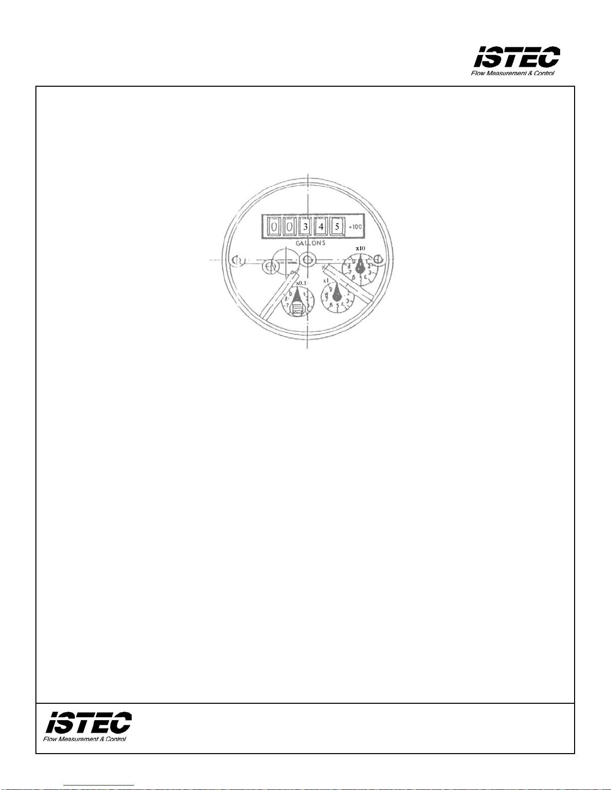
The 1800 Ser ies counter consists of a row of numbers (roller counter) and one or more
circular dials with rotating pointers. There is also a star shape d whe el th at ro tat e s whe ne ver
flow is present (tri c kl e indic a tor ).
The roller counter is calibrated in U.S. gallons and cannot be reset. It indicates the total flow
through the meter in gallons, hundreds of gallons, thousands of gallons, etc. The correct
multiplier is indicated on the face adjacent to the roller cou nter. In the example above, the
amount indica te d is 3 45 x 100 or 34, 5 00.
The circular dials indicate tenths of gallons, gallons, tens of g allons, etc. The respective
multiplier is marked adjacent to t he dial. For example, on the dial marked “x10”, each
number repr esents increments of ten gallons (i.e. 3 = 30 gallons, etc.) and one full rotation
equals 100 gallons. On the dial marked “x0.1”, each increment is one tenth (1/10) of a gallon
(4 = 0.4) and a full rotation of the dial r epresents a total of 1 gallon. Note tha t if the pointe r
is between two num be rs, the low er number is read.
The counter will roll around to zero and restart once it reaches its maximum reading.
HOW TO READ A 1800 SERIES WATER METER
SPARTA, NJ 07871
 Loading...