

Page 1
D- Storm Series
Rackmount Chassis ( 2U ~4U )
User’s Manual
w w w . i s t a r u s a . c o m
7 2 7 P h i l l i p s D r. C i t y o f I n d u s t r y , C A , 9 1 7 4 8 I ( 6 2 6 ) 3 0 3 - 8 8 8 5
Page 2
Copyright
Safety Instructions
Copyright 2009 by iStarUSA Inc., all rights reserved. No part of this
publication may be reproduced, transmitted, transcribed, stored in a
retrieval system, or translated without written permission of iStarUSA
Inc. 727 Phillips Drive, City of Industry CA 91748.
iStarUSA Inc. reserves the right to make modication and additions to
this product and manual without notice or taking any liability.
©
Trademarks
iStarUSA and D-Storm are all registered trandemark of iStarUSA, Inc. All
other trademarks here in are properties of their respective owners.
Disclaimer
iStarUSA Inc. assumes no liability for errors or omissions in this document, nor does iStarUSA Inc. make any commitment to update the
information contained here in. Pictures in this document are for demonstration purpose only and may not be the same as the actual product.
Please read this section carefully and follow the instructions for your
own safety and proper use of the device.
It also contains information on approval and interference suppression
of your machine.
Please pay attention to the warnings and instructions on the device and
in the manual.
.
- The device must be used in accordance to the instruction by iStarUSA.
- The electrical installation condition in the room must correspond to
the requirements of the respective regulations.
- Only use the cables supplied.
- Do not setup the device in areas around any heat sources or in a
damp location. Make sure the device has adequate ventilation.
- All plugs on the connection cables must be screwed or locked to
the housing.
- Do not touch the board or any other sensitive components without
all necessary anti-static protection.
iii
Page 3
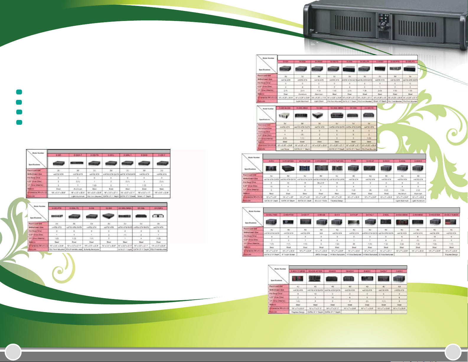
Table of Content
Introduction.......................................................................... 1
3U / 4U Chassis..................................................................... 2
2U Chassis............................................................................... 7
Technical Support & Warranty Policy........................... 11
D Series 3U
D Series 2U
D Series 2U
D Series 2U
D Series 4U
.
D Series 4U
D Series 4U
iii
Page 4
Introduction
D-400/ D-300 ( 4U / 3U )
The D-Storm Series rackmount chassis is a high-end industrial level
server enclosure line. From 1U to 4U, there are total over a dozen dierent model to satisfy various application requirements. D-Storm series
rackmount cases are designed according to the 19’’ rackmount standard
and work with most of the rack in today’s market. D-Storm can provide
your system a safe and durable housing. It can also work with many
dierent accessories to extend the capacity of your system.
The D-Storm series case has been designed and manufactured to
comply with the FCC standard for EMI and RFI resistance.
Features:
Standard 19” Rackmount case
1.2mm SECC Zinc-Coated Steel body or Aluminum
Lockable front door
Detachable card cage for easy installation and maintainence
Washableair filter
USB2.0 port in the found
Optional color door (Red/Blue/Silver/OEM Color)
OptionalDV R Backplane
Optionaltemperaturedetecting board and fan controller
FCC/CW industrial Class A approval
iStarUSA 4U industrial rackmount chassis D Storm D-400/ D-300.
Optional BPU or T Series enable hot-swappable storage capability.
It also supports up to seven add-on cards and total storage capacity of up to 5 storage drives for 1/0/5 raid conguration. D-400
provide your server or cluster maximum reliability and performance. Optional Aluminum Body reduces total chassis weight and
also provides enhanced thermal cooling solution.
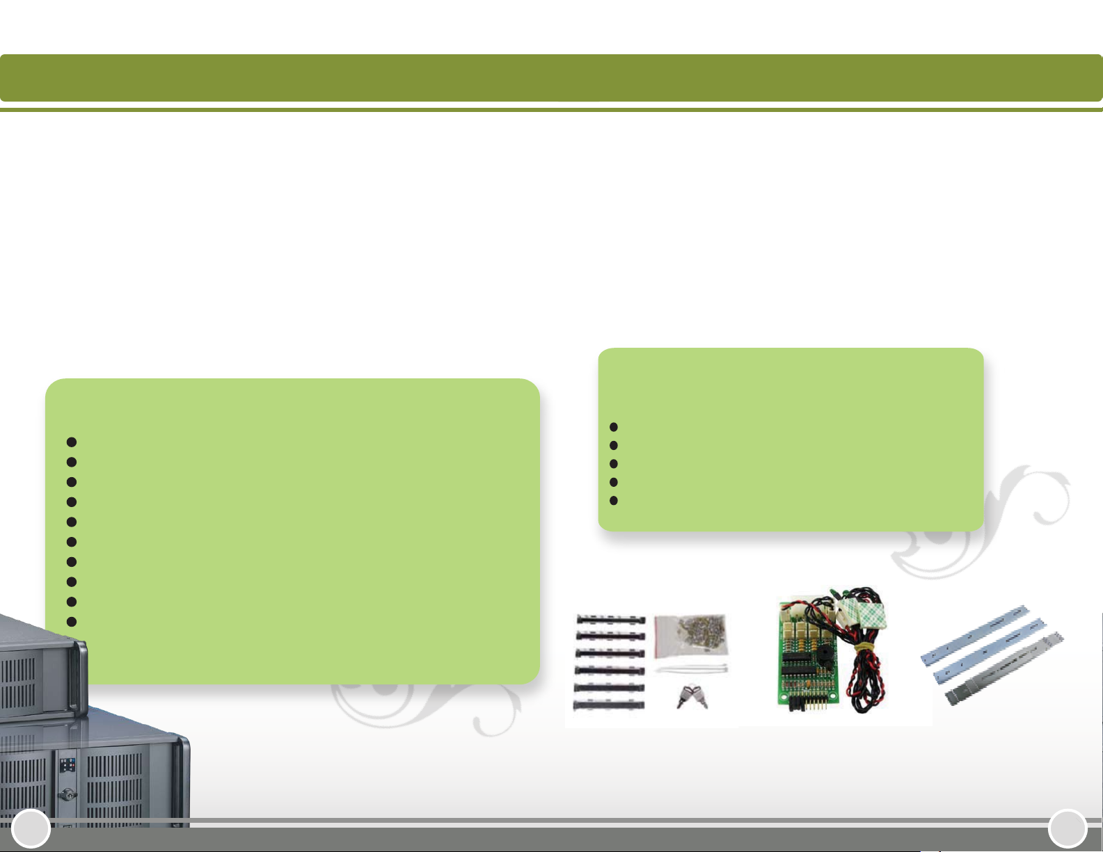
Package Contents:
D-Storm case
Accessory box (keys, screws, slot cover, cable tie )
Temperature and fan controller TC-ISF08 ( optional )
iStarUSA power supply (optional)
Sliding Rail 20’’, 24’’, 26’’. (optional )
4U /3U accessories
TC- ISF08 ( optional )
Sliding Rail (optional )
21
Page 5

D-400/ D-300 ( 4U / 3U )
4
2
2
3
1
6
7
4
5
10
8
9
D-400-7P
Front Panel Access:
10
5
Front Panel indicators
1
3 Temperature Alarm Indicator 1 6 Fan/Temperature Alarm Reset
7 Fan Failure Indicator 8 Temperature Alarm Indicator 2
Power On/Off 9 Reset
2x USB 2.0 Ports
4 Door Lock
System Power 2 HDD Activity
1
D-300L
Top View: ( exact looks may be different depending on model )
1 Drive Cage 2 Fan Bar
3 Temperature Sensor and Fan
Controller TC-ISF08 (optional)
Cleaning the Air Filter
To remove the air filter mat located in the front of
the system, please follow the steps below:
1. Open the door and remove the air filter.
2. To clean the air filter:
a. Rinse with water.
b. Vaccum or use the compressed gas
duster to clean.
c. Rinse with warm water.
DO NOT CLEAN WITH A PIERCING JET
4
Power Supply ( optional )
Polyester material witha UL Class 2 Rating
3
3. Wait until the air filter is completly dry.
43
Page 6

Installation
D-200 ( 2U )
4. Install motherboard and plug in all the USB cable and front control connector
USB connector drawing is shown on the box )
5. Install optional fan controller ( TC-ISF08 )
The 2U compact industrial rackmount chassis D Storm D-200. The full size
I/O supports all ATX motherboard. Combine with T-7 Hot-swappable cage
for raid conguration, and total up to 4 drive storage capacity. D-200
support 3 add-on cards include PCI, PCI-X, AGP, or PCI-Express architecture
that provide your server or cluster maximum exibility and performance.
Optional Aluminum Body reduces total chassis weight and also provides
enhanced thermal cooling solution.
Package Contents:
D-Storm case
Accessory box ( keys, screws, cable tie )
Temperature / fan controller board TC-ISF08. (optional )
iStarUSA power supply (optional)
Sliding rail 20’’, 24’’, 26’’. (optional )
Riser Card ( optional )
Accesories
Riser Card ( optional )
Sliding Rail (optional )
TC-ISF08 ( optional )
65
Page 7

D-200 ( 2U )
10
9
6
4
2
1
5
3
7
8
5
1
2
D-200
4
3
Front Panel Access:
10
Front Panel indicators
1
3 Temperature Alarm Indicator 1 6 Fan/Temperature Alarm Reset
7 Fan Failure Indicator 8 Temperature Alarm Indicator 2
Power On/Off
5
USB Port
System Power LED 2 HDD Activity LED
9 Reset
4 Door Lock
( Optional low profile backplane )
Top View: ( exact looks may be different depending on model )
1 Drive Cage 242U or redundant power supply
3
Horizontal expansion slots
5
1 x 80mm Fan
Riser supporting bar
87
Page 8

Riser Card Installation
1. Remove the supporting bar
2. Install two standoffs onto supporting bar
4. Mount the supporting bar onto the chassis
3. Riser card installed
( more info about riser card please go on to
www.istarusa.com, Product Suppport
Center)
109
Page 9

Technical Support Information
Hours: 9:00 AM - 5:30 PM PST
727 Phillips Drive
One Year Limited Warranty
This limited warranty applies to products manufactured or distributed by
iStarUSA Inc., under iStasrUSA Inc. brand name within the United States.
iStarUSA warrants that the product you have purchased from us or from an
authorized iStarUSA reseller is free from defects in materials and workmanship
under normal use for a period of one year from the original date of purchase.
Your sales receipt, shows the date of purchase of the product. This limited
warranty extends only to the original purchaser, is not transferable and excludes
disposable parts.
City of Industry, CA 91748
Tel: 1 (626) 303- 8885
FAX: 1 (626) 301-0588
Email: tech@istarusa.com
This limited warranty does not extend to any product that has been damaged or
rendered defective, as a result of accident, misuse, or abused by improper
installation, as a result of electrical surges or anomalies; by operating outsideIPC
usage parameters, by unauthorized modication of products, or as a result of
service by anyone other than iStarUSA. iStarUSA is not reponsible for damage to
or loss of any software programs data or information, or for damage to other
computer hardware and peripherals caused by the product.
Please contact our RMA department for repair or replacement of defective parts
under warranty, or request for RMA at www.istarusa.com
11 12
 Loading...