

Page 1

BPU-124DE-SS
User’s Manual
Features of product ---
Frame: Aluminum body & aluminum material for the front bezel
Interface: Support SATA-I, II, III & SAS I, II
Form Factor: 1 x 5.25” Bay for 4 x 2.5” SAS or SATA Hard Drive(SSD)
High performance transfer rate up to SATA 6Gb/s & SAS 6Gb/s
Support RAID Function (Note: SAS or SATA RAID control card needed )
Plug & play, hot swappable and with 15pin power co nnector
Support 2.5” single hard drive up to 14.5mm thickness in height
Built-in 2 X 4cm(4020) coolin g fan and the with mechani cal lock on the front tra y
LED for Power & HDD access and LED enable/disable Switch
---Solid HDD tray with strip-heat ventilating holder(picture A1) ---
HDD Installation:
For 2.5” SATA or SAS HDD (SSD):
Put HDD onto the tray as shown on Pic ture A-1 and use the provided screw s to
mount & secure HDD on the tray for each of the four.
---Safety Lock---
The mechanical lock design keeps each HDD staying inside of the unit and prevents
HDDs being taken out while they are in operation (See Picture B1 & B2.)
Picture B-1 Picture B-2
Picture A-1
Page 2
a) O PE N th e HD D Tra y:
Fi rstl y, unlock the HDD tray and pull out the handle to take o ut H DD tra y(Pictu re B-1 .)
b) L OC K th e HD D Tra y:
Aft er HDD is insta ll ed on th e HDD tray, then, slide in the HDD tr ay an d press the front
ha nd le f or wa rd a nd u se the k ey to lo ck the HDD tr ay onto t he u ni t (P icture B-2.)
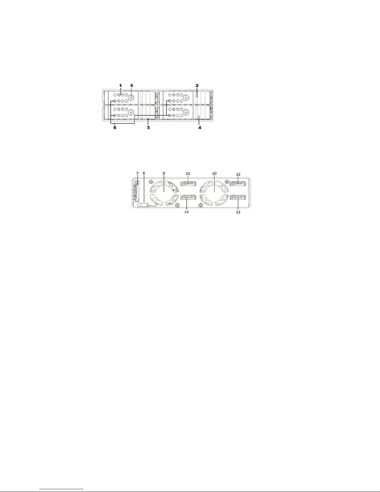
---Fro nt P an el & R ea l View -- - ( See Pi cture C & D)
Picture C:
C1 to C4 : HDD Tray C5 : Mechanical locker for front panel
C6 : LE D indi ca ti on : * Powe r ON : Solid Bl ue *Accessing: Purple blinking
*R ed blin king(fa st):O verheating *Red blin king(s lo w) : fa n fa ilur e
Picture D:
D7 : 15 pi n SATA po wer connector D8 : LE D Enable/D is ab le s witch
D9 – D 10: Cool in g Fa n
D11 , D1 2, D 13, D 14 : Fo r 7p in d at a si gn al p or ts
D8: HDD LED Switch Indication description:
a)
When it is se t t o “disable “ position, the front LED d oes NO T blink while HDD is bein g
accessed. In this case, th e LED shows s olid b lu e
b) Wh en it is set to “enable” position, it will blink in pu rple whil e HD D is bein g accesse d.
c) The def ault setti ng f or D 8 (H DD L ED Switch) is to “enable” position (HDD LED Enabl e) .
Picture C
Picture D
disable enable
 Loading...