

iStartek VT600 User Manual

File Name: VT600 User Manual Version 1.1
Project: VT600 Update Date: 2013-3-20
Sub Project: User Manual Page:
1 of21
GPS Vehicle Tracker
User Guide V1.1
VT600

File Name: VT600 User Manual Version 1.1
Project: VT600 Update Date: 2013-3-20
Sub Project: User Manual Page:
2 of21
Contents
1. Poduct Overview........................................................................................................................ 3
2. For Your Safety ......................................................................................................................... 3
3. VT600 Characteristics ................................................................................................................. 4
4. Getting Started .......................................................................................................................... 4
4.1 Hardware and Accessories ................................................................................................... 4
4.2 View ............................................................................................................................. 5
4.3 Functional Parts ................................................................................................................ 5
4.4 Connecting and Installation .................................................................................................. 6
5. Change Password ...................................................................................................................... 7
6. Time Zone ............................................................................................................................... 7
7. Track ..................................................................................................................................... 7
7.1 Track by SMS .................................................................................................................. 7
7.2 Track by Calling ................................................................................................................ 8
7.3 Track by Preset Interval ....................................................................................................... 8
7.4 Google Earth and Google Map .............................................................................................. 8
7.5 Track by GPRS between Server and Tracker ............................................................................ 9
7.5.1 Set Tracker’s GPRS ID ................................................................................................ 9
7.5.2 Set APN ................................................................................................................. 9
7.5.3 Set IP and Port ......................................................................................................... 9
7.5.4 Set DNS Server IP (optional) ......................................................................................... 9
7.5.5 Enable GPRS Tracking ................................................................................................ 9
7.5.6 Set GPRS Interval ..................................................................................................... 9
7.5.7 Set ACC Off Interval ................................................................................................... 9
7.5.8 Set ACC Off Interval Function ...................................................................................... 10
8. Authorization ....................................................................................................................... 10
9. Application Examples for Inputs .................................................................................................... 10
9.1 SOS Button Connection .................................................................................................... 10
9.2 Detecting Lock Status of Car’s Door or Trunk (Car Boot). ............................................................. 10
9.3 Connecting with Switch Sensors .......................................................................................... 11
9.4 Ignition Detection ............................................................................................................ 11
9.5 Analog Input (AD1) .......................................................................................................... 11
10. Speeding Alarm ..................................................................................................................... 12
11. Movement/Geo-fence ............................................................................................................... 12
11.1 Movement Alarm ............................................................................................................ 12
11.2 Geo-fence Alarm ............................................................................................................ 12
12. Track by Distance ................................................................................................................... 12
13. Listening-in (Optional) .............................................................................................................. 13
14. Set Sensitivity of Tremble Sensor ................................................................................................ 1 3
15. Output Control ....................................................................................................................... 13
15.1 Output Control (Immediate) ............................................................................................... 13
15.2 Output Control (Conditional) .............................................................................................. 13
15.3 Application Examples for Outputs ........................................................................................ 13
15.3.1 Engine Cut ........................................................................................................... 13
15.3.2 Connecting with Car Alarm ........................................................................................ 14
16. Heading Change Report ........................................................................................................... 14
17. Heartbeat ............................................................................................................................. 14
18. Track Log ............................................................................................................................. 15
18.1 Log by Interval .............................................................................................................. 15
18.2 Auto Log when no GPRS ................................................................................................. 15
18.3 Format Buffer ............................................................................................................... 15
19. Power Down ......................................................................................................................... 15
20. Get IMEI .............................................................................................................................. 15
21. Initialization .......................................................................................................................... 16
22. Password Initialization .............................................................................................................. 16
Annex 1. SMS Command List ......................................................................................................... 16
Annex 2. Troubleshooting .............................................................................................................. 20

File Name: VT600 User Manual Version 1.1
Project: VT600 Update Date: 2013-3-20
Sub Project: User Manual Page:
3 of21
1. Poduct Overview
VT600 is a GPS/GPRS based tracking device, specially developed and designed for vehicle real-time tracking and fleet
management.
VT600 has an inbuilt GPS module to obtain accurate position data. This device utilizes its GSM capability to send position
data to a specified mobile phone or server base for tracking and fleet management.
With internal memory, VT600 can store GPS coordinates when there is no GPRS connection, or at a specified interval
requested by the user.
One optional feature of VT600 is that a microphone can be linked and hidden somewhere inside the vehicle for listening to
the cabin.
VT600 has the following functions and features:
SMS and GPRS TCP/UDP Communication
AGPS ( with GSM Base Station ID)
Track on Demand
Show Location Directly on Mobile Phone
Track by Time Interval
Track by Distance
Listen-in (optional)
Anti-Jammer (optional)
GSM Blind Area Memory
Internal Memory for Logging
Inbuilt Motion Sensor for Power Saving
SOS Panic Button
Movement Alarm
Geo-fencing Control
Low Battery Alarm
peeding Alarm
GPS Blind Area Alarm (in/out)
Power-cut Alarm
Engine Cut (Stop Engine)
I/O: 3 digital inputs , 1 outputs and 1 analog inputs of 10 bits resolution
2. For Your Safety
Read these simple guidelines. Not following them may be dangerous or illegal.
Proper Connection
Do not connect any parts of this product to other incompatible devices. When
connecting with other devices, read instructions carefully to ensure proper
installation.
Qualified Accessories
Use original parts, qualified batteries and peripheral equipments to avoid
damage to VT600.
Safe Driving
Drivers should not operate this product while driving.
Qualified Service
Only qualified personnel can install or repair VT600.
Water Resistance
VT600 is not water resistant. Keep it dry. Install this device inside the vehicle or
use a waterproof bag for protection if necessary.
Confidential Phone Numbe
r
For safety reason, do not tell other people the mobile phone number of your
VT600 without taking precautions of security settings.

File Name: VT600 User Manual Version 1.1
Project: VT600 Update Date: 2013-3-20
Sub Project: User Manual Page:
4 of21
3. VT600 Characteristics
Items Specifications
Power Supply 10.6V - 36V / 1.5A
Backup Battery 500mAh
Normal power consumption 55mA/h
Dimension 65 x 61 x 26mm
Weight 90g
Work time 30 hours in power-saving mode and 7.5 hours in normal mode
Operating temperature -20° to 55° C
Humidity 5% to 95% Non-condensing
Frequency Quad Band GSM 850/900/1800/1900Mhz
GPS Module latest GPS SIRF-Star IV chipset
GPS Sensitivity -163Db
GPS Frequency L1, 1575.42 MHz
C/A Code 1.023 MHz chip rate
Channels 48 channel all-in-view tracking
Position Accuracy 10 meters, 2D RMS
Velocity Accuracy 0.1 m/s
Time Accuracy 1 us synchronized to GPS time
Default datum WGS-84
Reacquisition 0.1 sec., average
Hot start 1 sec., average
Warm start 35 sec., average
Cold start 35 sec., average
Altitude Limit 18,000 meters (60,000 feet) max
Velocity Limit 515 meters/second (1000 knots) max
LED 2 LED lights to show GPS/GSM status
Flash Memory 4MB
Button One SOS Button
Interface
3 digital inputs (2 negative and 1 positive triggering)
1 analog inputs
1 outputs.
4. Getting Started
This section will describe how to set up your VT600.
4.1 Hardware and Accessories
VT600 is supplied in a box which includes:
VT600 with battery, GPS antenna, GSM antenna, Wires with SOS button
File Name: VT600 User Manual Version 1.1
Project: VT600 Update Date: 2013-3-20
Sub Project: User Manual Page:
5 of21
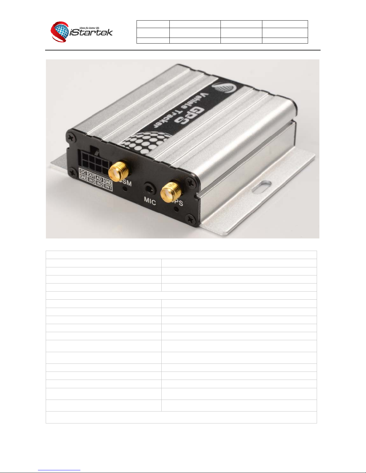
4.2 View
4.3 Functional Parts
GPS LED (Blue)
On One button is pressed or input is active
Flashing ( every 0.1 second) The unit is being initialized
Flashing (0.1 second on and 2.9 seconds off) VT600 has a GPS fix
Flashing (1 second on and 2 seconds off) VT600 has no GPS fix
GSM LED (Green)
On A call is coming in / a call is being made
Flashing ( every 0.1 second) The unit is being initialized
Flashing (0.1 second on and 2.9 seconds off) VT600 is connected to the GSM network
Flashing (1 second on and 2 seconds off) VT600 is not connected to the GSM network
Power On/Off Button
Press and hold for 3~5 seconds to turn on/off VT600
SOS Button
SOS button is connected with the wires. Press it to send SOS
alarm to the preauthorized phone number.
Mini USB
Used for firmware update, configuration on PC and exporting
stored data.
SIM Card Holder
Insert SIM card here
GSM Antenna
Connector for GSM antenna
GPS Antenna
Connector for GPS antenna
Screw Holes
There are 4 screw holes on the tracker, 2 along either side that act
as fixing points to the vehicle
Microphone (optional)
A microphone to be linked out for listening to the cabin
(wiretapping)
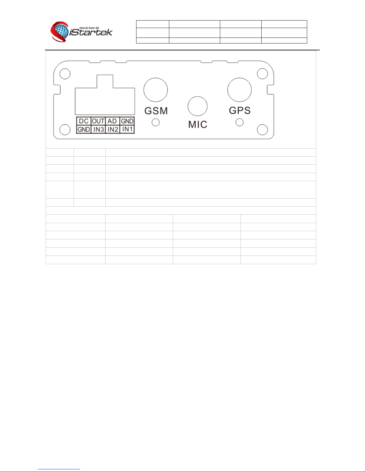
PINs Connector
File Name: VT600 User Manual Version 1.1
Project: VT600 Update Date: 2013-3-20
Sub Project: User Manual Page:
6 of21
PIN Color Function
Power Red DC In (power input). Input voltage: 10.6V~36V. 12V suggested
GND Black Ground
In White Digital Inputs. In1, In2 are negative triggering; In3 is positive triggering
Out Yellow
Outputs. Low voltage (0V) when effective and open drain when ineffective
Output open drain sink voltage (ineffective): 45V max.
Output low voltage sink current (effective): 500mA max.
AD Blue 10 Bits Resolution Analog Inputs. Input voltage: 0~6V
DC Characteristics of PINs
PIN Inactive Active Maximum
Input 1/2 Open drain or >1V 0V(GND) 45V
Input 3 Open drain or 0V(GND) >3V 45V
Output 1 Open drain 0V (GND) 45V/500mA
DC IN / 9-36V 45V
AD 1 / 0-6V 45V
4.4 Connecting and Installation
Read this manual before using your VT600. Check to make sure all parts are included in the packaging box.
4.4.1 Ensure that your VT600 has a working SIM card installed.
- Check that the SIM card has not run out of credit (test the SIM card in a phone to make sure it
can send and receive SMS)
- Check that the SIM card lock code is turned off
- If you require the function of sending an SMS location report to the authorized phone number
when it makes a call to the VT600, please make sure the SIM installed supports displaying
caller ID.
Before inserting SIM card, cut off the power for VT600.
Install SIM Card
- Unscrew and remove the front cover of VT600.
- Insert the SIM card by sliding it into the card slot with the chip module facing the connectors
on PCB.
- Replace the front cover and screw it in.
4.4.2 Antenna Connection
Connect the GSM Antenna to VT600.
Connect the GPS Antenna to VT600.
- GPS antenna is used to receive satellite signals in the sky. It should be fixed to face the sky, (It
is recommended to place this device under the windshield) and should not be covered or
shielded by any objects containing metal.
4.4.3 Find a suitable place inside the car for installing VT600. Wiring connections must be firm
and reliable. The joints should be wrapped tightly with insulating tape. The unused electrical
wire should be properly insulated.

File Name: VT600 User Manual Version 1.1
Project: VT600 Update Date: 2013-3-20
Sub Project: User Manual Page:
7 of21
Check to make sure all wirings have been connected correctly. Then connect the AVL unit to
the motor power.
Make a missed phone call the VT600 using a mobile phone to check if the call can go through.
The VT600 should reply with an SMS indicating long itude, latitude, speed and date.
5. Change Password
Command: W******,001,######
Description: Change user’s password.
Note:
1. ****** is user’s password and the default password is 000000. The tracker will only accept commands from a user with
the correct password. Commands with wrong password will be ignored.
2. ###### is the new password. Password should be 6 digits.
Example:
W000000,001,123456
W123456,001,999999
6. Time Zone
Command: W******,032,T
Description: Correct time to your local time
Note:
1. Default time of the tracker is GMT
2. This correction is applied to location reports by SMS and SMS alarms.
T=0, to turn off this function;
T=[-720,720] to set time difference in minutes to GMT.
For those ahead of GMT, input the time difference in minutes directly.
For example, for GMT+8, W000000,032,480. (8 Hours is 480 minutes)
‘-‘is required for those behind GMT.
For example, W000000,032,-120. (2 hours or 120 minutes behind GMT)
Example:
W000000,032,480
W000000,032,-120
7. Track
7.1 Track by SMS
- Track on Demand - Reply with longitude, latitude, speed and date
Command: W******,000
Description: To get the current location of the tracker, send this command as an SMS or make a telephone call directly to
the tracker. After doing so, the device will report its longitude and latitude by SMS with the format as follows:
Latitude = 22 32 36.63N Longitude = 114 04 57.37E, Speed = 40.5Km/h, 2011-12-24,01:50
Example:
W000000,000
- Track on Demand - Reply with a link to Google Maps
Command: W******,100
Description: Send this command to the tracker and you will receive an SMS with an http link. Click on the link and the
location will be shown directly on your mobile phone using Google maps. For example:
http://maps.google.com/?q=22.540103,114.082329
Note: Only smart phones and PDAs support this function.
Example:
W000000,100
 Loading...