

Ista ultego III smart plus Technical Description
ultego III smart plus
Technical description
32 22 101 001 a
Date: 07.04.2017
ista Middle East FZE
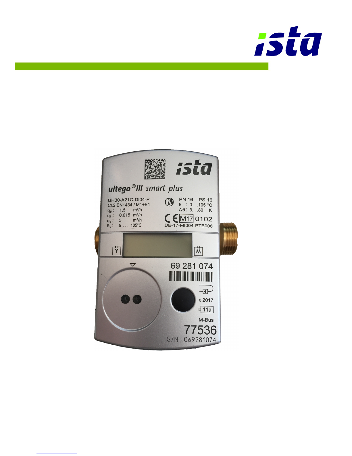
Ultrasonic heating and cooling meter
ultego III smart plus
Residential

Outstanding features 2/26
Outstanding features
Meter for measurement of flow and energy in a heat or cold circuit with water using the ultrasonic principle.
Important properties are:
Non-wearing due to non-moving parts
Compact, space-saving design
Robust all-metal measuring section
Exceptional robust DuraSurface™
Easy installation and read out
Fast and intelligent temperature measuring interval
Large, easy readable display
Flow measurement with maximum values
2 set days per month for 24 months (parameterizable)
Battery lifetime up to 11 years
Integrated communication for remote readout or system connection
Self-diagnosis

Contents 3/26
Contents
1 General notes ____________________________________________________________ 4
Other available documents __________________________________________________ 4
2 Safety information ________________________________________________________ 5
3 Technical data ___________________________________________________________ 7
Dimensions (qp 0,6 – 2,5 m³/h) _______________________________________________ 8
4 Installation _____________________________________________________________ 10
Installation notes _________________________________________________________ 10
Examples of installation ____________________________________________________ 11
Installation notes for sensor adapter set (sensors directly immersed) ________________ 12
4.1 Installation for cooling metering ___________________________________________ 12
5 Dimension of electronic unit _______________________________________________ 13
6 Operating elements ______________________________________________________ 15
6.1 Displaying current meter status ___________________________________________ 15
User loop “LOOP 0” _______________________________________________________ 15
Current values “LOOP 1” ___________________________________________________ 16
Previous month's values “LOOP 2“ ___________________________________________ 16
General / Communication “LOOP 3“ __________________________________________ 17
Other “LOOP 4“ __________________________________________________________ 17
6.2 Monthly values ________________________________________________________ 17
7 Resolution of the display __________________________________________________ 18
8 Power supply ___________________________________________________________ 18
9 Communication _________________________________________________________ 19
Electronic unit interfaces ___________________________________________________ 19
9.1 M-Bus _______________________________________________________________ 19
9.2 Pulse output __________________________________________________________ 19
9.3 Wireless M-Bus _______________________________________________________ 20
Predefined data telegrams _________________________________________________ 20
Data telegram F000 – stationary radio (sending interval 15 min) ____________________ 20
Data telegram F001 – mobile data reading (sending interval 20 sec, battery lifetime 6 years)
21
Data telegram F002 – mobile data reading (sending interval 34 sec, battery lifetime 11
years) 21
10 Error codes _____________________________________________________________ 22
11 Order codes (type number key) ____________________________________________ 23
12 Additional ordering information for wM-Bus __________________________________ 24
13 Pressure loss ___________________________________________________________ 25

General notes 4/26
1 General notes
Note: In the following text, the term meter refers to heat meter and
cooling meter, unless they are otherwise differentiated.
The meter is used as a meter for heating or cooling consumption measurement in systems with water.
The meter consists of a volume measurement unit, two fixed temperature sensors and an electronic unit that calculates the energy consumption from the
volume and temperature difference.
Other available documents
Operating and Installation Instructions T330
Respective module operating and installation instruction
Illustrated catalogue
Datasheet
Additional information is available on request.

Safety information 5/26
2 Safety information
The meter may only be used in building service engineering
systems and only for the applications described.
The local regulations (installation etc.) must be adhered to.
Adhere to the operating conditions according to the dial plate
during use. Non-adherence can cause hazards and the guarantee will expire.
The meter is only suitable for circulating water in heating systems.
The meter is not suitable for drinking water.
Be aware of sharp edges on thread and measuring tube.
The meter is suitable for circulating water in heating systems.
Adhere to the AGFW requirements regarding circulating water
(FW510).
Do not lift the meter by the electronic unit or by the adapter
plate.
Only personnel, trained in the installation and operation of meters in heating and cooling systems, may install and remove the
meter.
Only install or remove the meter when the pipes are pressureless.
After installing the meter, check the leak-tightness of the system.
Guarantee and calibration validity will lapse if the calibration
relevant security seal is broken.
Only clean the meter from outside with a soft, lightly wetted
cloth. Do not use any spirit or cleaning solvent.
As far as disposal is concerned, the meter is a waste electronic
appliance in the sense of European Directive 2012/19/EU
(WEEE) and it must not be disposed of as domestic waste. The
relevant national, legal regulations must be observed as the
appliance must be disposed of via the channels provided for this
purpose. The local and currently valid legislation must be observed.
The meter contains lithium batteries. Do not dispose of the
meter and the batteries with domestic waste. Observe the local
stipulations and laws on disposal.

Safety information 6/26
You can return the lithium batteries to the manufacturer for
appropriate disposal following use. When shipping please observe legal regulations, in particular, those governing the labelling and packaging of hazardous goods.
Do not open the batteries. Do not bring batteries into contact
with water or expose to temperatures above 80 °C.
The meter does not have any lightning protection. Ensure lightning protection by the house installation.

Technical data 7/26
3 Technical data
General
Measuring accuracy
Class 2 or 3 (EN 1434)
Environment class
A (EN 1434) for indoor installation
Mechanical class
M1 / M2 *)
Electromagnetic class
E1 *)
*) acc. to 2014/32/EU Directive on Measuring Instruments
Ambient humidity
< 93 % relative humidity at 25 °C,
without condensation
Max. height
2000 m above sea level
Storage temperature
-20 … 60 °C
Electronic unit
Ambient temperature
5 … 55 °C
Housing protection rating
IP 54 acc. to EN 60529
Power supply
Battery for 6 or 11 years
Operation threshold for T
0.2 K
Temperature difference T
3 K … 80 K
Temperature measurement range
0 ... 180 °C
LCD
7 digit
Optical interface
Standard, EN 62056-21
Communication
Optional
Separability
Always, cable length 1.5 m
Temperature sensor
Type
Pt500 acc. to EN 60751, not detachable
Connection type
Pt500, 2 wire technology
Cable length
1,5 m
Construction type
Bulb sensor ø 5.2 × 45 mm,
DS direct short, M10 x 27.5 mm
Temperature range
0 ... 105 °C
Volume measurement unit
Protection class
IP 54 acc. to EN 60529, optional IP 65
Mounting place
Hot side / cold side
Installation position
Any, horizontal or vertical
Flow straightening
None
Measuring range
1:100
Temperature range
5 … 105 °C
Maximum overload
qs = 2 x qp, permanent
Nominal pressure
PN16 (1.6 MPa; PS16)
PN25 (2.5 MPa; PS25)
qp
Overall length and connection
m³/h
0.6
110 mm (3/4 '')
190 mm (1 '')
1.5
110 mm (3/4 '')
130 mm (1 '')
190 mm (1 '')
2.5
130 mm (1 '')
190 mm (1 '')

Technical data 8/26
Nominal flowrate
q
p
Overall length
Connection
Maximum flowrate
q
s
Minimum flowrate
q
i
Response
threshold
(variable)
Pressure loss at
q
p
Kv-value ati Δp
1 bar
Kv-value at Δp
100 mbar
Pack size (LxBxH)
Weight
m3/h
mm G m3/h
l/h
l/h
mbar
m3/h
m3/h
cm
kg
0.6
110
G 3/41.2 6 1.2
150
1.5
0.5
15.5 x 13.5 x
12.0
0.8
0.6
190
G1
1.2 6 1.2
150
1.5
0.5
22.5 x 18.5 x
11.3
1.1
1.5
110
G 3/43
15 3 150
3.9
1.2
15.5 x 13.5 x
12.0
0.8
1.5
130
G1 3 15 3 160
3.8
1.2
15.5 x 13.5 x
12.0
0.8
1.5
190
G1 3 15 3 160
3.8
1.2
22.5 x 18.5 x
11.3
1.1
2.5
130
G1 5 25 5 200
5.6
1.8
15.5 x 13.5 x
12.0
0.8
2.5
190
G1 5 25 5 210
5.3
1.7
22.5 x 18.5 x
11.3
1.1
Tolerance of pressure loss: +/- 5%
Dimensions (qp 0.6 – 2.5 m³/h)
Fig. 1: Overview dimensions overall length 110 mm
Fig. 2: Overview dimensions overall length 130 mm (thread)
 Loading...