

Page 1
CCTV Lens Controller (LC-1)
Operation Manual (Version 1.3)
Page 2

Innovative Scientific Solutions, Inc.
Made in
U.S.A.
Table of Contents
Features ..................................................................................................................2
Specifications ..........................................................................................................3
NIC Network Setup ..................................................................................................4
Software Operation .................................................................................................5
Multi Control ...........................................................................................................8
Connections ............................................................................................................10
Wiring to Connector ................................................................................................12
Dimensions .............................................................................................................13
Export Disclaimer ....................................................................................................14
Appendix.................................................................................................................15
For questions or comments, please contact ISSI
Innovative Scientific Solutions, Incorporated
7610 McEwen Road
Dayton, OH 45459
Ph: (937) 630-3012
Fax: (937) 630-3015
Email: issi-sales@innssi.com
www.psp-tsp.com
Revision Date: 3/5/2018
1
Page 3
Innovative Scientific Solutions, Inc.
Features
The ISSI CCTV Lens Controller (LC-1) is a control device for motorized zoom lenses. The LC-1
can operate CCTV lenses with up to three-motors, with or without presets. The device is
operated via a graphical user interface and allows for presets to be saved (if using a lens with
preset ability) and then recalled at any time. The presets will save the position of the zoom,
focus and iris. Since the LC-1 is an Ethernet device, it can be networked with other LC-1s or
Ethernet devices. This makes communication and physical cable connections much simpler
than traditional serial lens controllers and also allows them to be operated over a longer
distance than serial devices. The IP address of the LC-1 can be configured to match the local
network. Uses for this device include closed-circuit television systems (CCTV), surveillance,
security, event monitoring, and optical based measurements in wind tunnels or other large
test facilities. The LC-1 comes with a Windows GUI for remote control and also has TCP/IP API
commands available for integration into existing user interfaces.
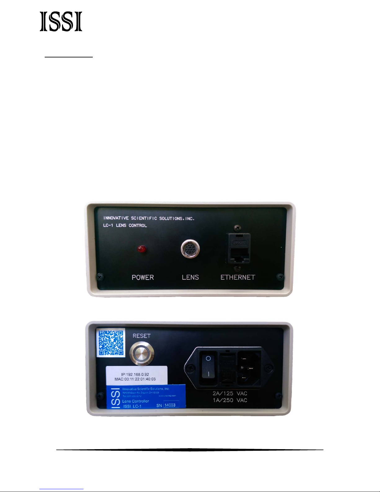
Figure 1: LC-1 Front Panel
Figure 2: LC-1 Rear Panel
2
Page 4
Innovative Scientific Solutions, Inc.
Power
100-240 VAC, 50-60 Hz, 0.3 A
Lens Voltage Range
9-12 V
Operating Temperature
2-60 ˚C
Interface
10/100 Mbps Ethernet
Lens Inputs
1
Presets
Unlimited, programmable
Software
Windows GUI, TCP/IP API
ECCN
EAR99
Power
Device is powered on
Lens
Hirose connection for motorized lens
Ethernet
Ethernet communication connection
Reset
Resets to default IP address, resets entire box
A VAC, A VAC
Device power connections
Specifications
Connections Description
Front Panel
Back Panel
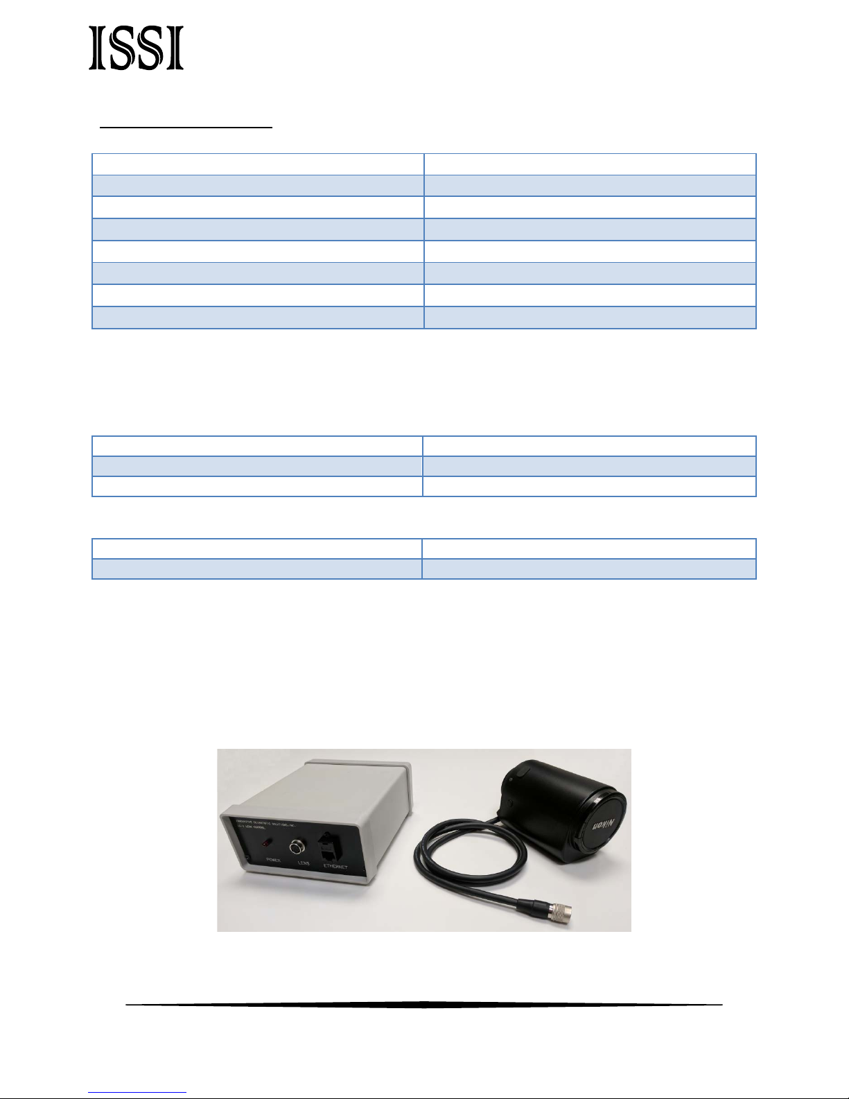
The LC-1 is shipped with:
1. Power cord
2. Ethernet cable
3. Lens cable with Hirose connector for wiring to lens
4. Software and manual on flash drive
**Lens not included**
3
Page 5
Innovative Scientific Solutions, Inc.
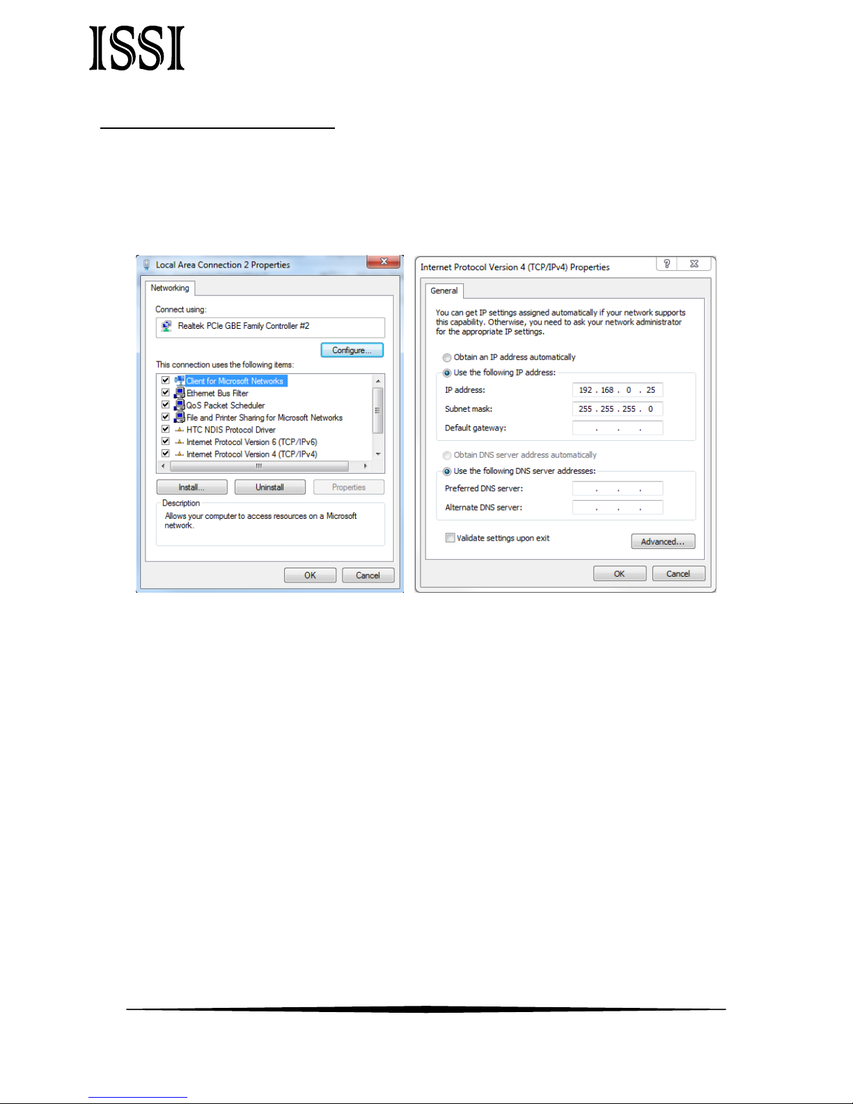
NIC Network Setup
The network on the PC NIC (network interface card) needs to be properly configured for
communication over the network. To do this, navigate to the ‘Network Connections’ page on
the control panel where the local networks of the computer are displayed. Right-click on the
network where the LC-1 is connected and select ‘Properties.’
From the ‘Local Area Connection X Properties’ window (above, left), click on ‘Internet Protocol
Version 4 (TCP/IPv4)’ and then press the ‘Properties’ button, now useable. This will open the
‘Internet Protocol Version 4 (TCP/IPv4) Properties’ window. This is where the IP addresses are
entered so that LC-1 can be reached over the network. The settings needed for
communication are IP Address and Subnet mask. The IP address of the NIC should use the
following conventions
IP Format: Network.Network.Subnet.Host
• LC-1 IP: 192.168.2.251
• NIC IP: 192.168.2.XXX
The NIC IP address should have the same network and subnet addresses but a unique host,
the last line of the IP address. The host can be any value 1-254 but different from the host
address of the LC-1. The subnet mask should be set to match that of the LC-1 which, by
default is 255.255.255.0. The Default Gateway and all other fields can be left blank.
4
Page 6
Innovative Scientific Solutions, Inc.
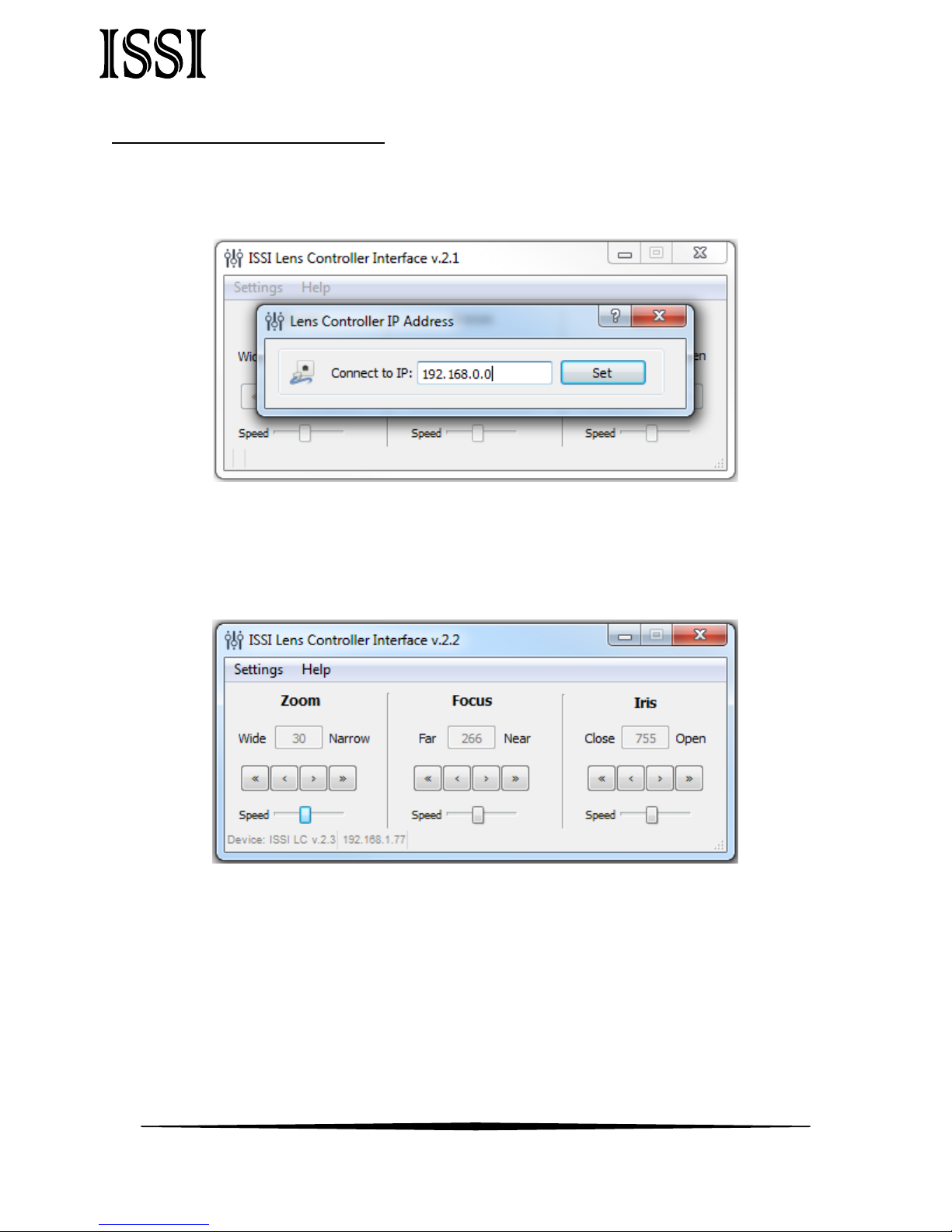
Software Operation
Open the software for the LC-1 from the desktop and it will ask for the IP of the connected LC-
1.
Enter the IP address of the LC-1 connected to the network. To communicate with multiple
LC-1s over this network (through a network switch), open up another instance of the
program on the desktop. Once connected, the GUI will show the current position of each
motor of the lens and the IP address which it is connected over in the bottom left corner.
The lens controller is made to work with three motor lenses with or without preset capability.
If the lens being used is not a three-motor lens as shown above the motor not present will not
operate on the GUI. The GUI displays the current positions of the Zoom, Focus and Iris
(Aperture). There are two sets of arrows below this which are used to move the position of
the motor. The single-arrow is slower moving for fine adjustments and the double-arrow is
faster for coarse adjustments. The overall speed of the movement of each motor can be
controlled using the sliding adjustment labeled ‘Speed.’ Moving to the right moves the
motor faster while moving left slows it down.
5
Page 7

Innovative Scientific Solutions, Inc.
Before using the lens controller with a lens, the limits of the motors can be found
using the Find Limits tool. For lenses with preset capability, this determines the minimum
and maximum motor positions. The motors of the lens will move through their minimum and
maximum points to establish the limits.
Once connected, the IP address of the lens controller can be changed if desired.
Under the Change IP window, the IP address can be updated.
If the toolbar is red, that means it is not a valid IP address. Type in the desired IP address and
click Apply to implement.
Always on Top makes the LC-1 software always appear as the front window for all windows
open on the desktop.
For lenses with preset capability, the save and load settings are used to save positions and
recall them on each motor of the lens. When the lens parameters are at their desired location,
those positions on each motor can be saved and later recalled. To save new settings, select
6
Page 8

Innovative Scientific Solutions, Inc.
Save Settings and enter a name for those lens settings. Settings are saved to the computer in
which the interface is open, not the lens controller itself.
To recall those lens settings, select Load Settings and the lens will return each motor to those
positions. The lens positions will be displayed in the Load Settings window for each preset.
When the position of the lens is being set, the above status window will show the progress.
Keyboard Commands
For easier access to preset positions, keyboard commands can be used to recall saved
positions. If a preset is saved with any single digit integer (0-9) it can be recalled by the
command Ctrl+0, 2……9. Individually recall these commands by holding down Ctrl then
pressing the number of the preset. To recall these presets, they must have the name of the
single digit integer being recalled.
For example, if a preset is saved as 1, then pressing Ctrl+1 will recall that preset.
7
Page 9

Innovative Scientific Solutions, Inc.
Multi Control
The Lens Controller Interface allows for master control of multiple LC-1s connected over a local
network. From the Multi LC-Control bar on the settings tab, the Multi Control window can be
opened.
The multi-control allows multiple LC-1s to be added and settings to be saved and recalled
from the master computer. To add LC-1s to the multi-control, click the Add IP button. This
will open a window where the IP address of an LC-1 can be entered. As with the presets for
single lens controllers, the settings saved in multi-mode are to the computer and not the lens
controller itself.
Once entered, the IP address will be added to the list in the window on the bottom left of the
multi-control window.
8
Page 10

Innovative Scientific Solutions, Inc.
To save the current settings for the LC-1s on the list in the multi-control window, click the
Save Current button. This will prompt a name for that set point to be entered.
Enter the name of the current position of the lens. If a name is entered that already exists, it
will ask if you would like to overwrite that file name.
Holding the cursor over an IP address on the list will display the current position of each
motor of that lens as shown above. To recall a set point for all selected LC-1s in multi-mode,
click the Load button. This will move each lens on each connected LC-1 to the positions
saved from that set point (+/- 2 units). Set points are saved on each computer, not on each
9
Page 11

Innovative Scientific Solutions, Inc.
LC-1. If settings are saved on one computer, they cannot be recalled on another. If using
multi-mode,
It should be noted that while all lenses will physically move to the set point from multimode, the lenses not connected to the master computer will not update their positions in
the software on their computer until the software is disconnected and reconnected.
Connections
Use a Cat5 or Cat6 Ethernet cable (provided) to connect to a PC network interface card or
network switch. The LC-1 is set up for universal power. The lens is supplied with a Hirose
connection to connect to the LC-1. This is a keyed connection and will only attach one way.
For users wishing to connect a specific lens other than that provided by ISSI, the connection
pin-out is described on page 12.
10
Page 12

Innovative Scientific Solutions, Inc.
The back panel contains the reset button. This reset button is used to reset the IP address to
the default IP address if the IP address was changed and is forgotten. To reset the LC-1 to the
default IP address, hold for 2 seconds and the IP address will be reset IP to 192.168.2.251.
Once changed to the default, the device will lose connection and need to be re-opened in the
GUI with the default IP address to connect. From there, the IP address can be changed to the
desired address by use of the Change IP tool previously explained.
If connection problems persist, check the connection of the Ethernet cable between the
computer NIC and the LC-1. To check that there is a physical connection, ping the IP address
of the LC-1 from the Command Prompt. To do this, open the command prompt window and
enter:
Ping XXX.XXX.XXX.XXX –t
11
Page 13

Innovative Scientific Solutions, Inc.
Input Voltage
85-264V, 50-60Hz, 0.3A
Interface
Ethernet
Protocol
UDP
Output Voltage
9 V (DC), 1.5A
Input Resolution
10 bits
Pin
Signal Type
Signal Name
1
9 VDC
Motor 2 (focus) Command Voltage +
2
9 VDC
Motor 2 (focus) Command Voltage -
3
9 VDC
Motor 1 (zoom) Command Voltage +
4
9 VDC
Motor 1 (zoom) Command Voltage -
5
GND
Ground 6 5 VDC
+5V 7 9 VDC
Motor 3 (iris) Command Voltage +
8
9 VDC
Motor 3 (iris) Command Voltage -
9
N/C
Future Use
10
0-5 VDC
Focus potentiometer input
11
0-5 VDC
Zoom potentiometer input
12
0-5 VDC
Iris potentiometer input
Wiring to Connector
**Disclaimer**: This is provided to show the specifications of the connector on the LC-1 and
the capabilities of the LC-1 itself. It is not a guarantee of performance with every CCTV or
zoom lens. Damage to the LC-1 due to improper wiring or connection to a lens is not covered
by the product warranty.
Specifications
Control Connector: Hirose HR10A-10R-12S(71)
12
Page 14

Innovative Scientific Solutions, Inc.
Pin
Color
1
Blue
2
Brown
3
Black Shield
4
Black Center
5
Red Shield
6
Red Center
7
Orange Center
8
White Shield
9
White Center
10
Yellow
11
Gray
12
Orange Shield
Control Cable Pinout
13
Page 15

Innovative Scientific Solutions, Inc.
Dimensions
14
Page 16

Innovative Scientific Solutions, Inc.
Export Disclaimer
Any and all underlying information and technology contained in this document may be
subject to U.S. export controls, including the Export Administration Act (50 U.S.C. Appx. §§
2401 et seq.) and the Export Administration Regulations ("EAR", 50 C.F.R. Parts 730-774), and
may be subject to export or import regulations in other countries. You are responsible for
complying with all trade regulations and laws both foreign and domestic. Except as
authorized by law or distributor agreement with ISSI, you agree and warrant not to export or
re-export the information to any country, or to any person, entity, or end-user subject to U.S.
export controls, including without limitation persons or entities listed on the U.S. Department
of Commerce Bureau of Export Administration's Denied Parties List and the U.S. Department
of Treasury's Specially Designated Nationals. You further represent and warrant that no U.S.
federal agency has suspended, revoked, or denied your export privileges.
15
Page 17

Innovative Scientific Solutions, Inc.
Appendix
ISSI Lens Controller API
Based on UDP protocol, 1337/UDP port is used for communication.
Action: Get controller f/w version
Command: “ver” (hex: 766572)
Answer: “ISSI LC=2.3”
Action: Change controller IP address to 192.168.1.2
Command: “ChangeIP=192.168.1.2”
(hex: 4368616e676549503d3139322e3136382e312e32)
Answer: no answer, controller will set IP and restart
Action: Get current motors values
Command: “Current” (hex: 43757272656e74)
Answer: “Current=XXX,YYY,ZZZ”
Where XXX – zoom position value, YYY- focus position value, ZZZ – iris position value.
Action: Move Zoom Narrow during X ms
Command: “ZoomN=X”
Answer: “Zoom=Y”, where Y – current value of Zoom motor
Action: Move Zoom Wide during X ms
Command: “ZoomW=X”
Answer: “Zoom=Y”, where Y – current value of Zoom motor
Action: Move Focus Far during X ms
Command: “FocusF=X”
Answer: “Focus=Y”, where Y – current value of Focus motor
Action: Move Focus Near during X ms
Command: “FocusN=X”
Answer: “Focus=Y”, where Y – current value of Focus motor
Action: Move Iris Open during X ms
Command: “IrisO=X”
Answer: “Iris=Y”, where Y – current value of Iris motor
Action: Move Iris Close during X ms
Command: “IrisC=X”
16
Page 18

Innovative Scientific Solutions, Inc.
Answer: “Iris=Y”, where Y – current value of Iris motor
Action: Set zoom motor value to X
Command: “setZoom=X”
Answer: “zoomDone”, it may take for a while to position the motors.
Action: Set focus motor value to X
Command: “setFocus=X”
Answer: “focusDone”, it may take for a while to position the motors.
Action: Set iris motor value to X
Command: “setIris=X”
Answer: “irisDone”, it may take for a while to position the motors.
Action: Stop all motors
Command: “setStop”
Answer: no answer
Action: Motors limits detection (for all tree motors)
Command: “FindLimits”
Answer: in separate packets:
zoomMax=XXX
irisMax=XXX
focusMax=XXX
17
 Loading...