

ISSI IS31SE5104 Quick Start Manual

IS31SE5104 4-CH CAPACITIVE TOUCH SENSOR EVALUATION BOARD GUIDE
DESCRIPTION
The IS31SE5104 is an ultra low power, fully integrated
solution for capacitive touch applications with up to 4
surfaces. The chip allows electrodes to project sense
fields through any dielectric such as glass or plastic.
On-chip calibration logic continuously monitors the
environment and automatically adjusts on-and-off
threshold levels to prevent false sensor activation.
The IS31SE5104 is fully programmable via a 400kHz
I2C serial bus protocol.
FEA TURES
Supply voltage from 2.7V to 5.5V
I2C interface, 1.8V/2.8V is allowed
Auto offset compensation
Fully integrated sense controller with 4 capacitive
touch inputs
Interrupt driven output
Adjustable sensitivity with external capacitor or by
internal register
Low power consumption
ESD HBM 8kV
IC controller in QFN-16 (3mm × 3mm)
QUICK START
RECOMMENDED EQUIPMENT
5.0V, 500mA power supply
ABSOLUTE MAXIMUM RATINGS
≤ 5.5V power supply
Caution: Do not exceed the conditions listed above, otherwise
the board will be damaged.
PROCEDURE
The IS31SE5104 evaluation board is fully assembled
and tested. Follow the steps listed below to verify
board operation.
Caution: Do not turn on the power supply until all connections
are completed.
1) Connect the ground lead of the power supply to
the EVB GND terminal and the positive lead to the
EVB VCC terminal. Or use the connector (DC IN)
with a power adaptor: jack size 3.5mm x 1.35mm.
2) Turn on the power supply and pay attention to the
supply current. If the current exceeds 100mA,
please check for a circuit fault.
EVALUATION BOARD OPERATION
This evaluation board is controlled by a
pre-programmed P89LPC922 (80C51 core).
Figure 1: Photo of IS31SE5104 Evaluation Board
IS31SE5104 evaluation board has 4 touch surfaces
designed on a 2mm thick acrylic board to induce a
dielectric. Each touch surface has an associated LED
that will light when the corresponding surface area is
touched.
C
LED
IS31SE5104
Figure 2: Capacitance Detection
BODY
C
PCB
The capacitance (C
increases as it approaches the sense area. The
IS31SE5104 detects this increase in capacitance and
turns on the associated LED.
SOFTWARE SUPPORT
Please refer to the integrated program.
Please refer to the datasheet for more information.
) of an approaching finger
BODY
Integrated Silicon Solution, Inc. – www.issi.com 1
Rev . A, 11/19/2014
IS31SE5104 4-CH CAPACITIVE TOUCH SENSOR EVALUATION BOARD GUIDE
ORDERING INFORMATION
Part No. Temperature Range Package
IS31SE5104-QFLS2-EB -40°C ~ +85°C (Industrial) QFN-16, Lead-free
Table 1: Ordering Information
For pricing, delivery, and ordering information, please contacts ISSI’s analog marketing team at
analog@issi.com
or (408) 969-6600.
KEY1
KEY2
KEY3
KEY4
CON1
DC IN
KEY PAD
U2
EXT
SDA
SCL
SDB
SDB
INT
SDA
SCL
1
20
19
18
10
14
9
3
2
LPC922
VCC
R1
R4
10KR34.7KR24.7K
10K
R16
R15
R14
R13
1K
P0. 0/ CMP2/ KBI0
P0.1/CIN2B/KBI1
P0.2/CIN2A/KBI2
P0.3/CIN1B/KBI3
P1. 2/ T0/ SCL
P0. 6/ CMP1/ KBI6
P1. 3/ INT0 /SDA
P1. 6
P1. 7
P0.4/CIN1A/KBI4
P0. 5/ CMPREF/KBI5
P0. 7/T 1/KBI7
P1. 0/T XD
P1. 1/RXD
P1. 5/ RST
P3.1/XTAL1
P1. 4/ INT1
P3. 0XT AL2/CL KOUT
U3
1
VDD
LDO
R8
510
R5
510
R6
510
R7
510
SD
GND
C2
0.1uF
VOUT
BP
U1 IS31SE5104
1
VCC
14
GND
16
GND
2
Cap1
3
Cap2
4
Cap3
5
Cap4
TP2
C3
10uFC11uF
TP1 1
JP1
OPEN=E XT C T RL
C10NCC9NCC8NCC7
3
2
EXT
VCC
NC
3VVCC
5
C5
C4
1uF
10nF
4
TP5
SDB
5
SCL
4
SDA
3
INT
2
GND
1
10
SD
9
INTB
8
SDA
6
SCL
7
AD
15
OUT4
13
OUT3
12
OUT2
11
OUT1
3V
C6
15
VDD
VSS
0.1uF
17
16
13
12
11
4
6
8
7
5
D4 D3 D2 D1
P0. 4
P0. 5
TXD
RXD
RST
3V
P0. 5
P0. 4
RST
GND
RXD
INT
TXD
TP3
5
4
3
2
ICP
1
2
3
TP4
VCC
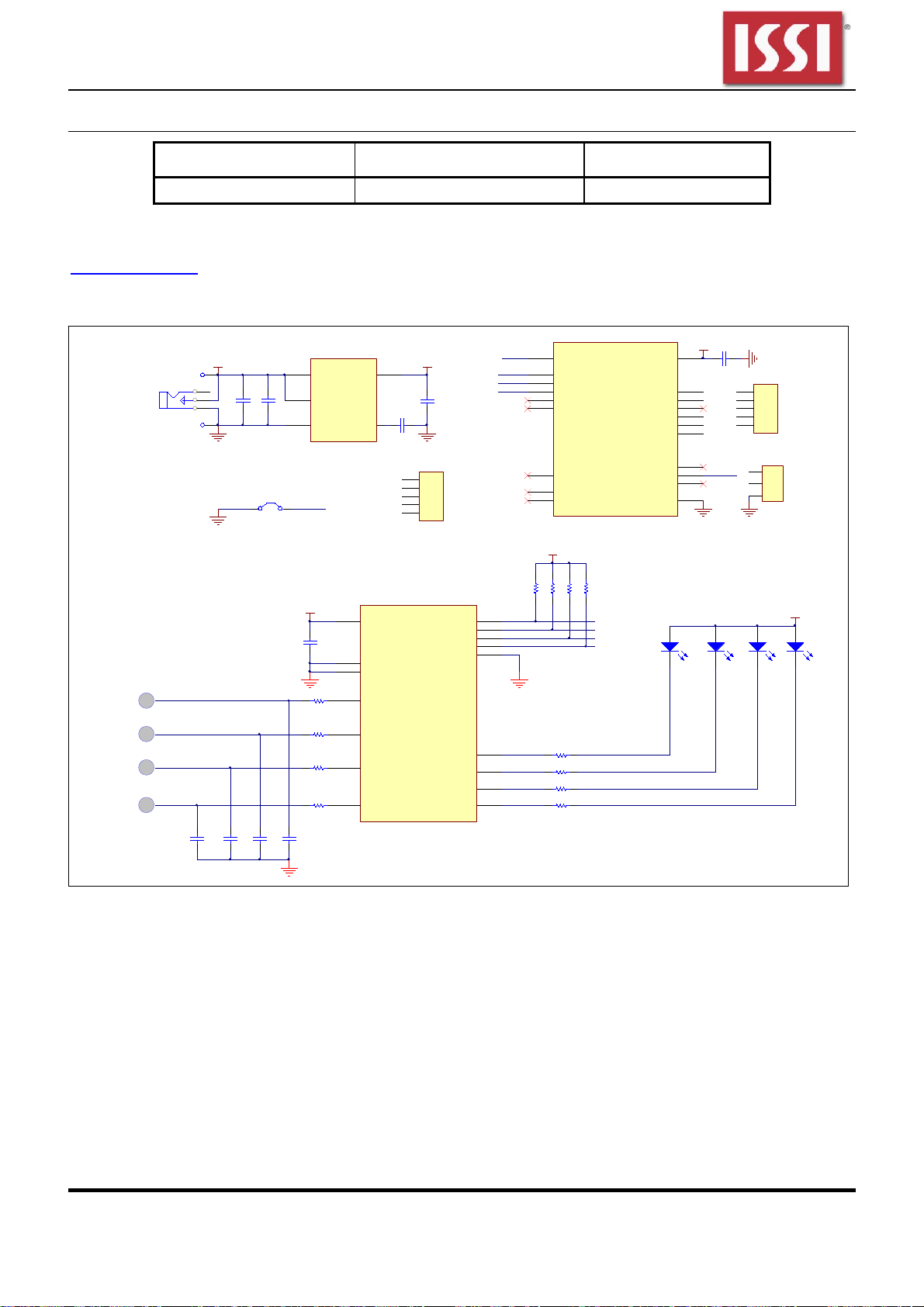
Figure 3: IS31SE5104 Application Schematic
Integrated Silicon Solution, Inc. – www.issi.com 2
Rev . A, 11/19/2014
 Loading...