

ISSI IS31LT3918 User Manual
IS31LT3918 T8 Lighting Evaluation Board Guide
Description
The IS31LT3918 LED driver IC is a peak current
detection buck converter which operates in constant off
time mode. It operates over a very wide input voltage
supply range of 6VDC to 450VDC or 110VAC/220VAC.
The IS31LT3918 incorporates the special feature of
switch dimming by detecting OFF-ON cycles of the main
power switch. When the switch is cycled within a 2
second period (typical) the device automatically switches
the dimming level to the next step. As a result, dimming
can be achieved without replacing any wiring in the
original system. There are multiple modes of switch
dimming that the user may configure, 2 steps or 3 steps,
as well as different levels of dimming via the external
pins DIM1 and DIM2.
Features
User configurable switch dimming levels
3% output current accuracy
Over current, voltage and temperature protection
High efficiency (typical up to 95%)
Wide input voltage range: 6VDC~450VDC or
85VAC~ 265VAC
Linear and PWM dimming
Very few external components
Applications
DC/DC or AC/DC LED driver applications
Signal and decorative LED lighting
Backlighting LED driver
Quick Start
Recommended Equipment
85 ~ 265VAC 50~60Hz power supply
LED array (12 in series and 24 in parallel)
Main power switch
Absolute Maximum Ratings
≤ 265VAC power supply
≤ 42V Vout (Total Vf)
Caution: Do not exceed the conditions li
sted above, otherwise the board will be
damaged or the output will be limited
Procedure
The IS31LT3918 Evaluation Board is fully assembled
and tested. Follow the steps listed below to verify board
operation.
Caution: Do not turn on the power supply until all
connections are completed.
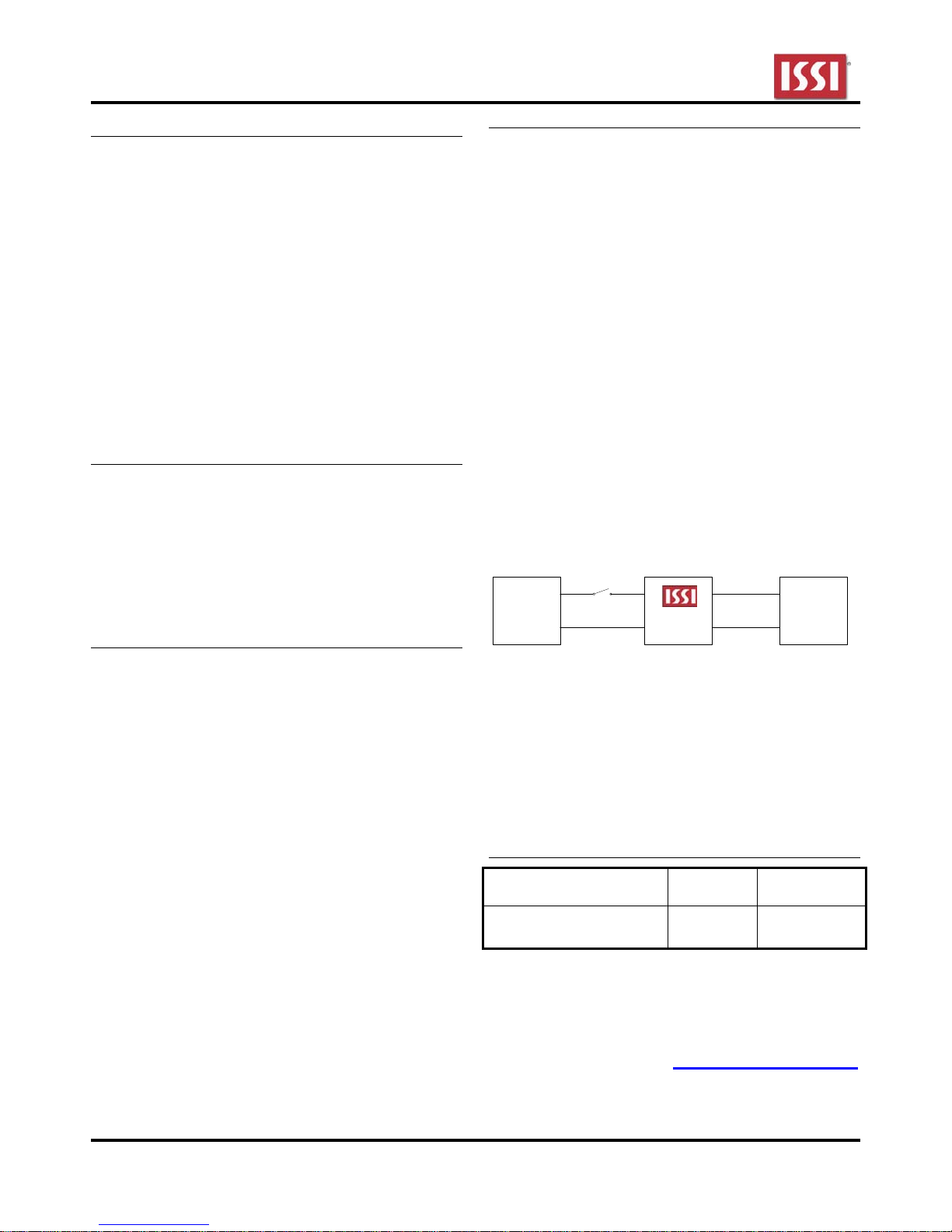
Switch
L
Input
85 – 265VAC
1) Connect the positive terminal of the LEDs to the
2) Connect the input pins (L and N) of the Evaluation
3) Turn on the power supply.
N
LED+ pin of the Evaluation Board and the negative
terminal of the LEDs to the LED- pin of the
Evaluation Board.
Board via the main power switch to AC power
supply.
L
N
IS31LT3918
Board
LED+
LED-
LED
Array
Ordering Information
PART #
IS31LT3918_GRLS2_EBT8
TEMP
RANGE
-40 °C to
85°C
IC
PACKAGE
SO-8
(5.0 x 6.0mm)
For pricing, delivery, and ordering information, please contact ISSI at analog_mkt@issi.com
or call +1-408-969-6600
Integrated Silicon Solution, Inc. – www.issi.com 1
R1.0, 18/12/2012
IS31LT3918 T8 Lighting Evaluation Board Guide
Detailed Description
Switch Dimming
The action of the main power switch can be divided into
two types. The first is “normal switch operation”
wherein the switch is toggled from ON to OFF,
remaining OFF for longer than 2 seconds (typical). The
other is “switch dimming action” wherein the switch is
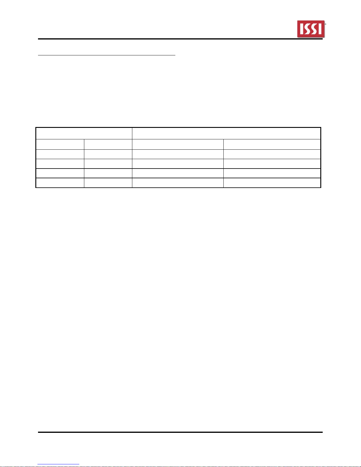
Setting Dimming Current-Level
Pin Name / Setting DESCRIPTION
DIM 1 DIM 2 Functionality Dimming Levels
Floating Floating No Dimming 100%
Floating GND 3 (Three) - levels of dimming 100% -- 30% -- 100%
GND Floating 3 (Three) - levels of dimming 100% -- 50% -- 100%
GND GND 2 (Two) - levels of dimming 100% -- 50% -- 20% -- 100%
toggled from ON to OFF and back ON within 2 seconds
(typical). When the device experiences normal switch
operation, it merely powers on in the first state when
the power switch is toggled to ON, and the device turns
off when the main power switch is changed to OFF.
Switch dimming output current levels are configured by
connecting the DIM1 and DIM2 pins as indicated in the
table below:
When operating the power switch normally the device
will always power up at 100% output current. The
operation of the power switch and the configuration of
the DIM1 and DIM2 pins control the dimming process
as follows:
1. When DIM1 and DIM2 pins are both floating, there
is no switch dimming, and the output current is
100% of the programmed value when the power is
on.
2. When DIM1 is floating and DIM2 is GND, the
output current is:
a) 100% at power on.
b) The first switch dimming action causes the
current to change to 30%.
c) A second switch dimming action causes the
current to return to 100%.
d) A fourth switch dimming action has the same
effect as the first switch dimming action.
e) Subsequent switch dimming actions causes
the cycle to continue.
3. When DIM1 is GND and DIM2 is floating, the
dimming sequence is as described in (2) above,
except that the current sequence is
100%-50%-100%.
4. When both DIM1 and DIM2 are connected to GND,
the dimming sequence is as described in (2) above,
except that the current sequence is
100%-50%-20%-100%.
If the switch is operated normally, that is, switched ON
once after being in the OFF position for a long time, or if
both the DIM1 and DIM2 pins are floating, then the
output current always starts up at the initial value of
100%.
Note: Because the main power switch is used to initiate
the switch dimming function, the device must have a
large enough external capacitor on VIN to maintain
device operation for 2 seconds. Please refer to the
schematic for specific values.
Integrated Silicon Solution, Inc. – www.issi.com 2
R1.0, 18/12/2012
IS31LT3918 T8 Lighting Evaluation Board Guide
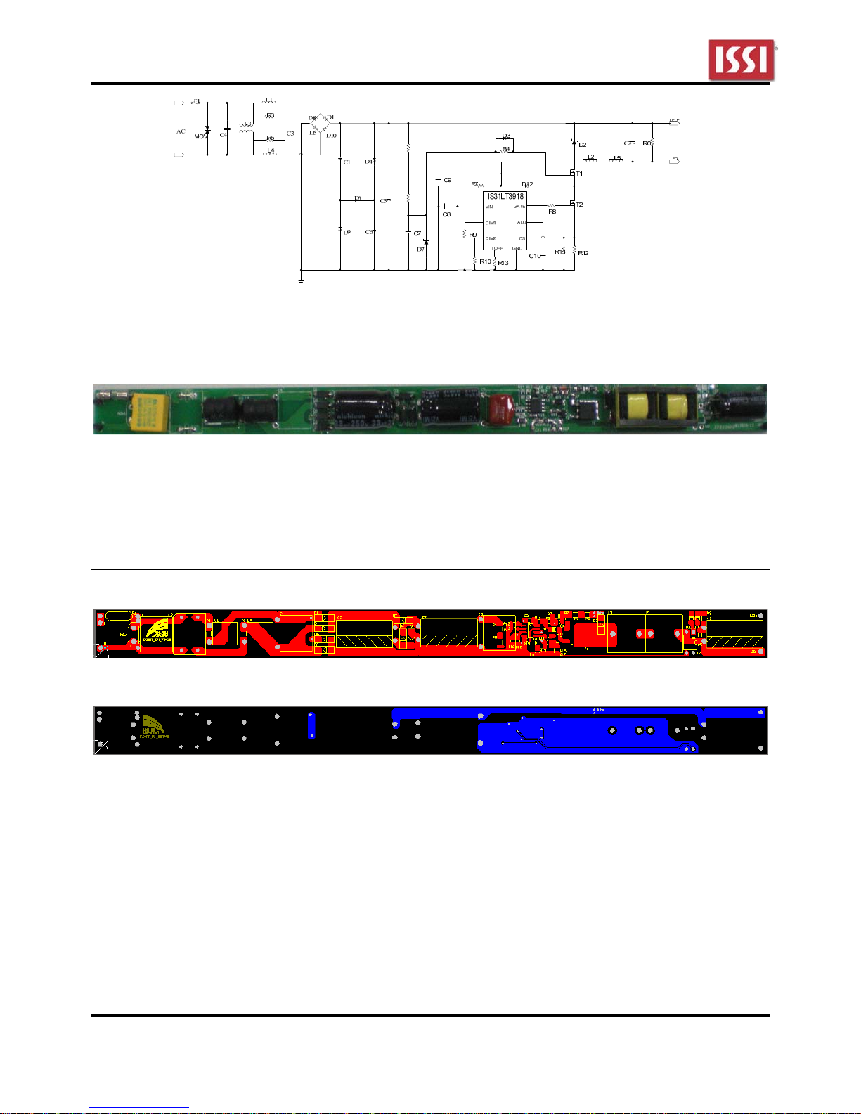
R1
R6
Figure 1 IS31LT3918 Evaluation Board Schematic
Note: ISSI Evaluation Board does not include a LED array
Figure 2. Picture of Evaluation Board
NOTE: Physical dimensions are (L x W x H): 25.1mm x 17mm x 12mm
PCB Layout
Figure 3. PCB Layout- Top Layer
Figure 4. PCB Layout- Bottom Layer
Integrated Silicon Solution, Inc. – www.issi.com 3
R1.0, 18/12/2012
 Loading...