

Page 1

IS31IO8972 EVB user guide
IS31IO
8972
EVB user
guide
Rev.A
2019-3-14
Integrated Silicon Solution, Inc. – www.issi.com 0
Rev. A, 14/03/2019
Page 2

IS31IO8972 EVB user guide
GENERAL DESCRIPTION
FEATURES
The IS31IO8972 is a stand-alone Controller Area
Network (CAN) protocol controller with the embedded
CAN transceiver. It supports CAN 2.0B standard and the
maximal bit rate is 1 Mb/s. It is capable of transmitting
and receiving standard and extended message frames. It
includes eight independent transmit buffers with
auto-dispatch function and 1024-byte receive FIFO with
12 ID acceptance filtering and message management.
The MCU communication is implemented via an industry
standard Serial Peripheral Interface (SPI) and I2C bus.
Single + 5V power supply
Maximal operating clock up to 24MHz
Built-in one CAN controller according to CAN
protocol version 2.0B.
0~8 byte message length
Standard and extended data frames
Programmable bit rate up to 1Mb/s
Support for remote frames
1024 Bytes receive FIFO
12 full acceptance filters
8 full filter masks
8 transmit buffers with abort feature
Auto-dispatch function for each transmit buffer
Listen mode
Loop-back mode for self-test operation
Built-in CAN transceiver full support CAN v2.0B
specification
Built-in IOSC up to 16MHz
Hardware interface
High speed SPI interface up to 3Mb/s bit rate
Supports SPI mode 0,0 and 1,1
High speed Slave I2C interface up to 2Mb/s bit
rate
Interrupt output pin with selectable enables
Low power CMOS technology
50mA active current typical
1mA standby current
External wake-up by SPI/ I2C and CAN receiver
Industrial operating temperature range (-40°C ~
+125°C)
20-pin SSOP packages
RoHS compliance
Integrated Silicon Solution, Inc. – www.issi.com 1
Rev. A, 14/03/2019
Page 3

IS31IO8972 EVB user guide
ORDERING INFORMATION
Operating temperature -40°C to 125°C
Order Part No. Package QTY
IS31IO8972-SALS4 SSOP-20, Lead-free 75/Tube
Integrated Silicon Solution, Inc. – www.issi.com 2
Rev. A, 14/03/2019
Page 4
IS31IO8972 EVB user guide
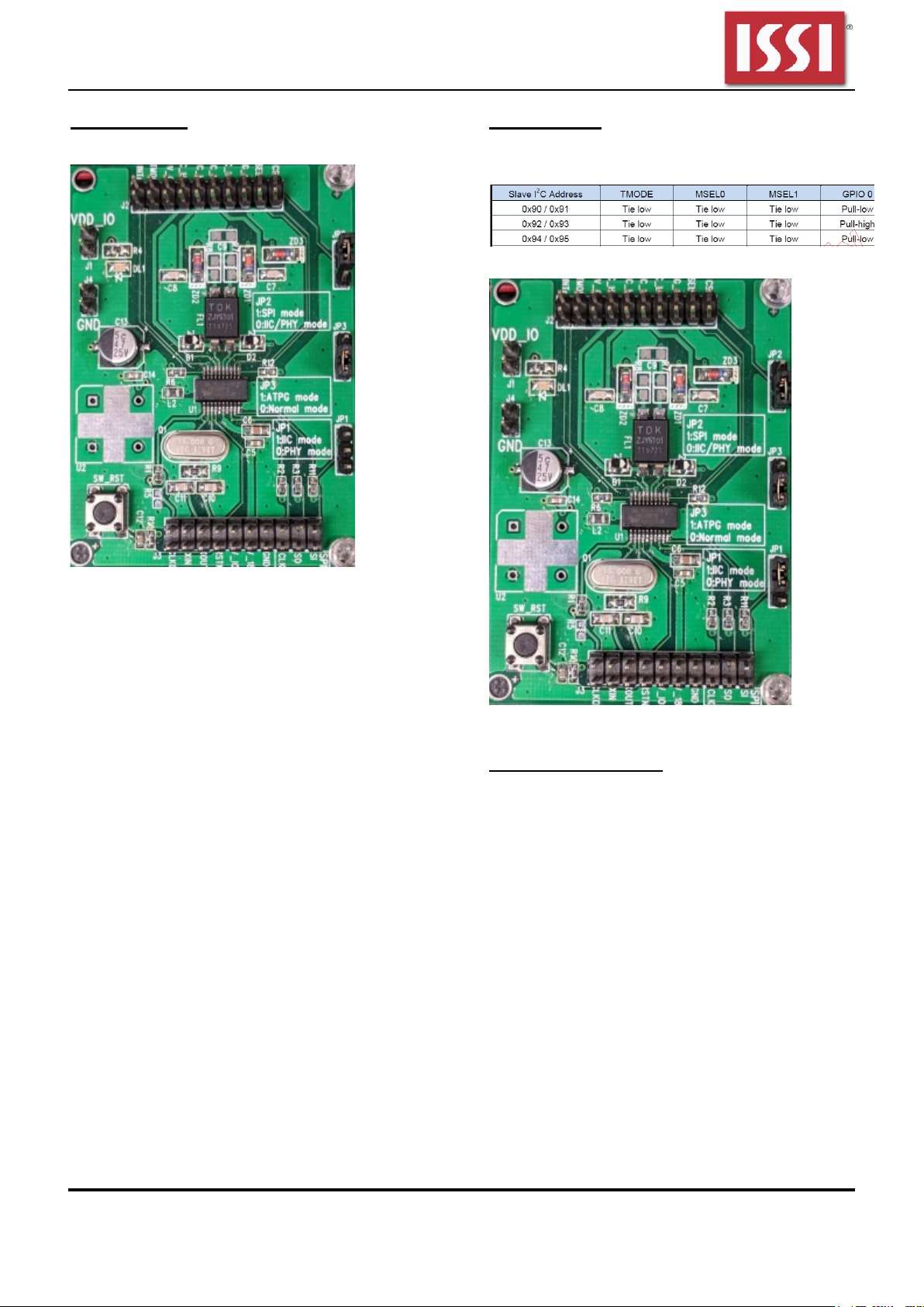
Using SPI Mode
Connections to host MCU: CSn, SI, SO, CLK
Figure 1: Jumper configuration for SPI Mode
Using IIC Mode
Connections to host MCU: CLK(as SCL), SO(as
SDA); Slave I2C Address to be configured as the
following table.
Figure 2: Slave I2C Address configuration table
Figure 3: Jumper configuration for IIC Mode
ATPG Mode, PHY Mode
Are both test modes for internal testing purpose only.
Integrated Silicon Solution, Inc. – www.issi.com 3
Rev. A, 14/03/2019
Page 5
IS31IO8972 EVB user guide
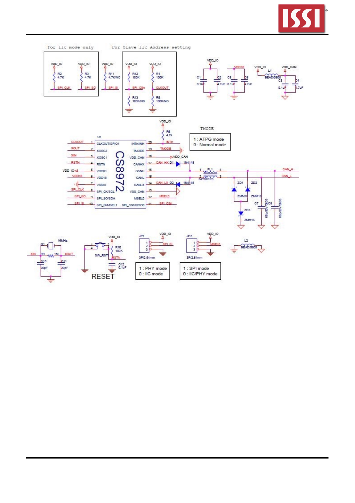
Figure 4: Evaluation Board Schematic
Integrated Silicon Solution, Inc. – www.issi.com 4
Rev. A, 14/03/2019
Page 6

IS31IO8972 EVB user guide
BILL OF MATERIALS
Item Symbol Description Qty Supplier Part No.
1 C1,C3,C5,C12,C14 0.1uF 5
2 C2,C4,C6 4.7uF 3
3 C8,C7 68p/50V/0805 2
4 C9 47n/50V/0805 1
5 C11,C10 20pF 2
6 C13 47uF 1
7 DL1 LED 1
8 D2,D1 1N4148 2
9 FL1 ZJYS81R5 1
10 JP1,JP2,JP3 3P/2.54mm 3
11 J4,J1 CON2 2
12 J3,J2 HEADER 10X2 2
13 L2,L1 BEAD/0805 2
14 Q1 NOD/11.059MHz 1
15 R1,R2,R3,R6,R11,R12 4.7K 6
16 R4 470 1
17 R5 NC 1
18 R7,R8 1.3K/0805/1% 2
19 R9 1M 1
20 R10 100K 1
21 SW_RST1 SW PUSHBUTTON 1
22 U1 IS31IO8972 1
23 U2 Socket (OSC 12MHz) 1
24 ZD1,ZD2,ZD3 16V 3
Figure 5: Bill of Materials
Integrated Silicon Solution, Inc. – www.issi.com 5
Rev. A, 14/03/2019
Page 7

IS31IO8972 EVB user guide
Figure 6: Evaluation Board Component Placement Guide - Top Layer
Integrated Silicon Solution, Inc. – www.issi.com 6
Rev. A, 14/03/2019
Page 8

IS31IO8972 EVB user guide
Figure 7: Evaluation Board PCB Layout - Top Layer
Integrated Silicon Solution, Inc. – www.issi.com 7
Rev. A, 14/03/2019
Page 9

IS31IO8972 EVB user guide
Figure 8: Evaluation Board Component Placement Guide - Bottom Layer
Integrated Silicon Solution, Inc. – www.issi.com 8
Rev. A, 14/03/2019
Page 10

IS31IO8972 EVB user guide
Copyright © 201
8 Integrated Silicon Solution, Inc. All rights reserved. ISSI reserves the right to make changes to this
specification and its products at any
Figure 9: Evaluation Board PCB Layout - Bottom Layer
time without notice. ISSI assumes no liability arising out of the application or use of any information, products or services described herein. Customers are
advised to obtain the latest version of this device specification before relying on any published information and before placing orders for products.
Integrated Silicon Solution, Inc. does not recommend the use of any of its products in life support applications where the failure or malfunction of the
product can reasonably be expected to cause failure of the life support system or to significantly affect its safety or effectiveness. Products are not
authorized for use in such applications unless Integrated Silicon Solution, Inc. receives written assurance to its satisfaction, that:
a.) the risk of injury or damage has been minimized;
b.) the user assume all such risks; and
c.) potential liability of Integrated Silicon Solution, Inc is adequately protected under the circumstances
Integrated Silicon Solution, Inc. – www.issi.com 9
Rev. A, 14/03/2019
Page 11

IS31IO8972 EVB user guide
Copyright © 2018 Integrated Silico
n Solution, Inc. All rights reserved. ISSI reserves the right to make changes to this specification and its products at any
REVISION HISTORY
Revision
Detail Information Data
A Initial release 2019.03.14
time without notice. ISSI assumes no liability arising out of the application or use of any information, products or services described herein. Customers are
advised to obtain the latest version of this device specification before relying on any published information and before placing orders for products.
Integrated Silicon Solution, Inc. does not recommend the use of any of its products in life support applications where the failure or malfunction of the
product can reasonably be expected to cause failure of the life support system or to significantly affect its safety or effectiveness. Products are not
authorized for use in such applications unless Integrated Silicon Solution, Inc. receives written assurance to its satisfaction, that:
a.) the risk of injury or damage has been minimized;
b.) the user assume all such risks; and
c.) potential liability of Integrated Silicon Solution, Inc is adequately protected under the circumstances
Integrated Silicon Solution, Inc. – www.issi.com 10
Rev. A, 14/03/2019
Page 12

IS31IO8972 EVB user guide
APPENDIX Ⅰ: Basic APIs for accessing SPI mode (with CS8961)
void SetSPI()
{
XFR_PADMOD0 = 0x80; // SPI_MOD: P72=SCS, P73=MOSI, P74=MISO, P75=MSCK
SPICR = 0x7C; // SPIE=0, SPIEN, MSTR, CPOL=1, CPHA=1, SCKE=1, -, SPIMR = 0x03; // 1Byte INT(polling flag), SCK=SYSCLK/8, MSB first
}
//-----------------------------------------------------------------------------// read one byte
uchar SPI_read_1(uchar addr)
{
uchar dout;
SPIMR |= 0x20; // clear FIFO
SPIMR &= 0xDF;
SPIST &= 0x7F; // clear SSPIF
P7 &= 0xFB; // P72: SCS low
SPIDATA = 0x23; // "read" instruction
while ((SPIST & 0x80) == 0x00){}; SPIST &= 0x7F; // wait and clear SSPIF
dout = SPIDATA;
SPIDATA = addr;
while ((SPIST & 0x80) == 0x00){}; SPIST &= 0x7F; // wait and clear SSPIF
dout = SPIDATA;
SPIDATA = 0x55; // dummy
while ((SPIST & 0x80) == 0x00){}; SPIST &= 0x7F; // wait and clear SSPIF
dout = SPIDATA;
P7 |= 0x04; // P72: SCS high
return dout;
}
//-----------------------------------------------------------------------------// read n bytes starting from remote_addr
void SPI_read_n(uchar remote_addr, uchar n, uchar* rd_buffer)
{
uchar tmp;
SPIMR |= 0x20; // clear FIFO
SPIMR &= 0xDF;
SPIST &= 0x7F; // clear SSPIF
P7 &= 0xFB; // P72: SCS low
SPIDATA = 0x23; // "read" instruction
while ((SPIST & 0x80) == 0x00){}; SPIST &= 0x7F; // wait and clear SSPIF
tmp = SPIDATA;
SPIDATA = remote_addr;
while ((SPIST & 0x80) == 0x00){}; SPIST &= 0x7F; // wait and clear SSPIF
tmp = SPIDATA;
while(n>0)
{
SPIDATA = 0x55; // dummy
while ((SPIST & 0x80) == 0x00){}; SPIST &= 0x7F; // wait and clear SSPIF
*rd_buffer = SPIDATA;
rd_buffer++;
n--;
}
P7 |= 0x04; // P72: SCS high
}
//-----------------------------------------------------------------------------// bit modify
void SPI_bit_modify(uchar addr, uchar mask, uchar din)
{
uchar i;
SPIMR |= 0x20; // clear FIFO
SPIMR &= 0xDF;
SPIST &= 0x7F; // clear SSPIF
P7 &= 0xFB; // P72: SCS low
SPIDATA = 0x25; // "bit modify" instruction
while ((SPIST & 0x80) == 0x00){}; SPIST &= 0x7F; // wait and clear SSPIF
SPIDATA = addr;
while ((SPIST & 0x80) == 0x00){}; SPIST &= 0x7F; // wait and clear SSPIF
Integrated Silicon Solution, Inc. – www.issi.com 11
Rev. A, 14/03/2019
Page 13

IS31IO8972 EVB user guide
SPIDATA = mask;
while ((SPIST & 0x80) == 0x00){}; SPIST &= 0x7F; // wait and clear SSPIF
SPIDATA = din;
while ((SPIST & 0x80) == 0x00){}; SPIST &= 0x7F; // wait and clear SSPIF
P7 |= 0x04; // P72: SCS high
for (i=0;i<0xFF;i++)
{
_nop_();
}
}
//-----------------------------------------------------------------------------// write one byte
void SPI_write_1(uchar addr, uchar din)
{
uchar i;
SPIMR |= 0x20; // clear FIFO
SPIMR &= 0xDF;
SPIST &= 0x7F; // clear SSPIF
P7 &= 0xFB; // P72: SCS low
SPIDATA = 0x22; // "write" instruction
while ((SPIST & 0x80) == 0x00){}; SPIST &= 0x7F; // wait and clear SSPIF
SPIDATA = addr;
while ((SPIST & 0x80) == 0x00){}; SPIST &= 0x7F; // wait and clear SSPIF
SPIDATA = din;
while ((SPIST & 0x80) == 0x00){}; SPIST &= 0x7F; // wait and clear SSPIF
P7 |= 0x04; // P72: SCS high
for (i=0;i<0xFF;i++)
{
_nop_();
}
}
//-----------------------------------------------------------------------------// write n bytes to remomte_addr
void SPI_write_n(uchar remote_addr, uchar n, uchar* local_data)
{
uchar i;
SPIMR |= 0x20; // clear FIFO
SPIMR &= 0xDF;
SPIST &= 0x7F; // clear SSPIF
P7 &= 0xFB; // P72: SCS low
SPIDATA = 0x22; // "write" instruction
while ((SPIST & 0x80) == 0x00){}; SPIST &= 0x7F; // wait and clear SSPIF
SPIDATA = remote_addr; // remote starting address
while ((SPIST & 0x80) == 0x00){}; SPIST &= 0x7F; // wait and clear SSPIF
while (n>0x00)
{
SPIDATA = *local_data;
while ((SPIST & 0x80) == 0x00){}; SPIST &= 0x7F; // wait and clear SSPIF
local_data++;
n--;
}
P7 |= 0x04; // P72: SCS high
for (i=0;i<0xFF;i++)
{
_nop_();
}
}
Integrated Silicon Solution, Inc. – www.issi.com 12
Rev. A, 14/03/2019
Page 14

IS31IO8972 EVB user guide
APPENDIX Ⅱ: Basic APIs for accessing IIC mode (with CS8961)
void I2C_write_1(unsigned char addr, unsigned char wr_dat)
{
unsigned char i;
I2CMCR = 0x04; while((I2CMCR & 0x01)); // STOP
I2CMSA = SLAVE_ADDR|0x00;
I2CMBUF = addr;
I2CMCR = 0x03; while((I2CMCR & 0x01)); // START+SEND
I2CMBUF = wr_dat;
I2CMCR = 0x05; while((I2CMCR & 0x01)); // SEND+STOP
for (i=0;i<0xFF;i++)
{
_nop_();
}
}
//==============================================================================
// write n bytes
void I2C_write_n(uchar addr, uchar length, uchar* local_data)
{
unsigned char i;
for(i=0;i<length;i++)
{
I2C_write_1(addr,local_data[i]);
addr++;
}
}
//==============================================================================
unsigned char I2C_read_1(unsigned char addr)
{
unsigned char i;
unsigned char ReadData;
I2CMCR = 0x04; while((I2CMCR & 0x01)); // STOP
I2CMSA = SLAVE_ADDR|0x00;
I2CMBUF = addr;
I2CMCR = 0x03; while((I2CMCR & 0x01)); // START+SEND
I2CMSA = SLAVE_ADDR|0x01;
I2CMCR = 0x07; while((I2CMCR & 0x01)); // START+RECEIVE+STOP
for (i=0;i<0xFF;i++)
{
_nop_();
}
ReadData = I2CMBUF;
return ReadData;
}
//==============================================================================
void I2C_read_n(uchar addr, uchar length, uchar* rd_buffer)
{
unsigned char i;
for(i=0;i<length;i++)
{
rd_buffer[i] = I2C_read_1(addr);
addr++;
}
}
Integrated Silicon Solution, Inc. – www.issi.com 13
Rev. A, 14/03/2019
 Loading...