

ISSI IS31AP4915 Quick Start Manual
IS31AP4915 Class-G Audio Power Amplifier Evaluation Board Guide
Part No.
Temperature Range
IC Package
IS31AP4915-SLS2-EB
-40°C to +85°C (Industrial)
QFN-16 (4mm x 4mm)
Description
The IS31AP4915 is an audio power amplifier
designed to drive ceramic speakers in portable
applications. The IS31AP4915 outputs 20V
less than 1% THD+N while operating. The
IS31AP4915 features differential inputs for
improved noise rejection and a low power
shutdown mode. The IS31AP4915 is unity-gain
stable and uses external gain-setting resistors. The
IS31AP4915 evaluation board allows easy
characterization of IS31AP4915 features. It
provides connectors for audio inputs, audio outputs,
and power supply. Please note that ceramic
speakers are not included with kit.
P-P
with
Features
Integrated Charge-Pump Power Supply–No
Inductor Required
Short-Circuit and Thermal Protection
Pop Reduction Circuitry
20V
High Electric-Sound Efficiency
Package: QFN-16 (4mm x 4mm)
Voltage Swing into Ceramic Speaker
P-P
Quick Start
Recommended Equipment
5V, 2A power supply
Audio input source (i.e. iPod/mp3 player)
Ceramic speaker
Caution: Do not exceed the conditions listed above,
otherwise the board will be damaged.
Absolute Maximum Ratings
≤6.5V power supply
Caution: Do not exceed the voltage listed above. Doing so
may cause damage to the board.
Procedure
The IS31AP4915 evaluation board has been fully
assembled to allow easy demonstration of the
amplifier’s characteristics. Follow the steps listed
below to verify board operation.
Caution: Do not turn on the power supply until all circuitry
connection points are joined. Operate only under safe
conditions.
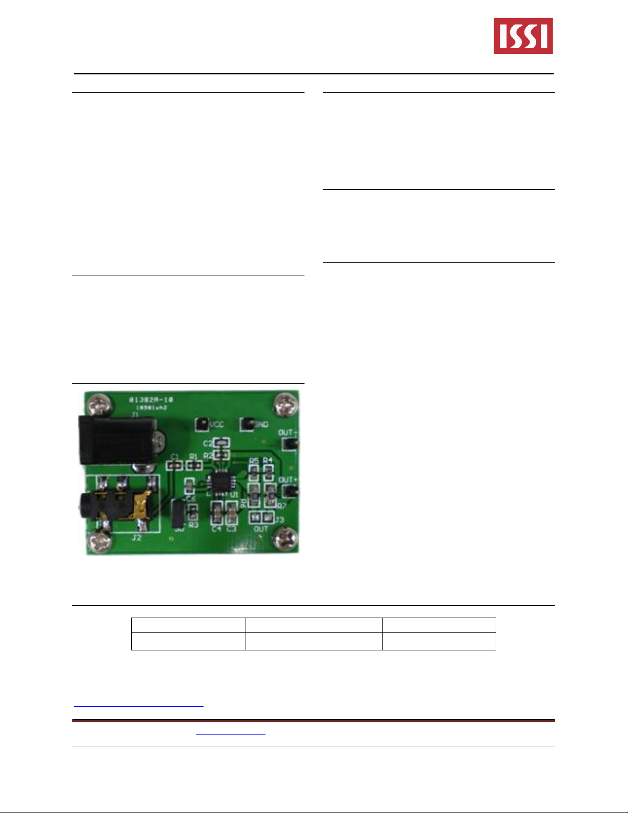
1. Connect the ceramic speaker to the OUT+ and
OUT-
2. Connect the audio source to the J2 by using a
3.5mm headphone connector
3. Connect the ground terminal of the power
supply to the GND pin and the positive terminal
to the VCC pin, OR connect the power supply
to J1.
4. Turn on the audio source
5. Turn on the power supply
Figure 1: Photo of IS31AP4915 Evaluation Board
Ordering Information
For pricing, delivery, and ordering information, please contact the ISSI team at
analog_mkt@issi.com or (408) 969-6600.
Integrated Silicon Solution, Inc. – http://www.issi.com 1
RevA, 1/10/2013
Table 1: Ordering Information
IS31AP4915 Class-G Audio Power Amplifier Evaluation Board Guide
Evaluation Board Operation
The evaluation board provided features the IS31AP4915 Class-G audio power amplifier IC, a ceramic
amplifier ideal in applications that require high efficiency. The board requires a DC power supply range of
3.5V to 6.5V, with constant 2A supply current. The board accepts stereo input. The audio source is amplified
to provide an 11V
Input-Blocking Capacitors
A series of DC, input-blocking, capacitors are required to be placed following the audio signal input circuitry.
This capacitor block the DC portion of the audio source and allow the IS31AP4915 inputs to be properly
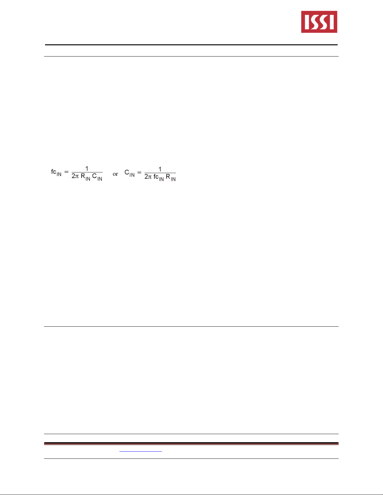
biased to provide maximum performance. These capacitors form a high-pass filter with the input impedance
of the IS31AP4915. The cutoff frequency is calculated using Equation (1). For this calculation, the
capacitance used is the input-blocking capacitor and the resistance is the input impedance of the
IS31AP4915. Because the gains of both the IS31AP4915 is fixed, the input impedance remains a constant
value. Using the input impedance value from the operating characteristics table, the frequency and/or
capacitance can be determined when one of the two values is given.
output voltage to drive ceramic speaker. It is shipped with a fixed gain of 48 V/V.
P-P
Charge Pump Flying Capacitor and PVSS Capacitor
The charge pump flying capacitor serves to transfer charge during the generation of the negative supply
voltage. The PVSS capacitor must be at least equal to the charge pump capacitor in order to allow
maximum charge transfer. Low ESR capacitors are an ideal selection, and a value of 10μF is typical.
Capacitor values that are smaller than 10μF can be used, but the maximum output power is reduced and
the device may not operate to specifications
Decoupling Capacitors
The IS31AP4915 require adequate power supply decoupling to ensure that the noise and total harmonic
distortion (THD) are low. A good low equivalent-series-resistance (ESR) ceramic capacitor, typically 1μF,
placed as close as possible to the device VDD lead works best. Placing this decoupling capacitor close to
the IS31AP4915 is important for the performance of the amplifier. For filtering lower frequency noise signals,
a 10μF or greater capacitor placed near the audio power amplifier would also help, but it is not required in
most applications because of the high PSRR of this device.
Layout Recommendations
Exposed Pad Option for IS31AP4915 Package
The exposed metal bonding pad on the device package must be soldered down to pads on the PCB for
enhanced reliability. The pad on the PCB must be soldered to a floating plane.
Caution: Do NOT connect to power or ground.
SGND and PGND Connections
The SGND and PGND pins of the IS31AP4915 must be routed separately back to the decoupling capacitor
in order to provide proper device operation. If the SGND and PGND pins are connected directly to each
other, the part functions without risk of failure, but the noise and THD performance do not meet the
specifications.
Software Support
Please refer to the integrated software program that comes with the evaluation board.
Integrated Silicon Solution, Inc. – http://www.issi.com 2
RevA, 1/10/2013
 Loading...