


BM77EVB
Evaluation Kit
User’s Guide
iSSC Te chnologies Corp.
Revision History
Date Revision Content Version
2014/10/03 Revision for BM77EVB WPS, Oct 2014 0.4
© 2014 ISSC Technologies Corp.
1

TableofContents
1. Overview ................................................................................................................................. 3
1.1. BM77EVB Description .................................................................................................................... ...............3
1.2. Features .............................................................................................................................................. ..........4
2. Block Diagram ....................................................................................................................... 5
3. Interface Description ............................................................................... ........ .... .... .... .......... 6
3.1. Power Switch Settings ............................................... ............................................................................. ......7
3.2. Mode Definitions .......................................................................... .................................................................7
3.3. Mode Switch Settings ....................................................................................................................................7
4. Quick Start Guide to Using the BM77EVB .......................................................................... 9
4.1.Bluetooth SPP connection to Android Smartphone/Tablet ..... ....................................... .. 9
4.2.Bluetooth Low Energy Data Connection to iOS Device .................................................. 17
5. Appendix A: BM77SPP03 Module PIN Assignment ......................................................... 27
6. Appendix B: BM77EVB Schematic .................................................................................... 29
7. Appendix C: Q & A .............................................................................................................. 32
8. Appendix D: Reversion History ......................................................................................... 33
© 2014 ISSC Technologies Corp.
2
1. Overview
This document describes the hardware and software for the ISSC BM77EVB evaluation kit.
The BM77EVB allows the designer to evaluate and demonstrate the capabilities of the ISSC BM77 Dual Mode
Bluetooth RF Module. The evaluation board includes an integrated configuration and programming interface for
plug-and-play capability. It also includes on-board connection and data status LEDs enabling rapid prototyping and
fast time to market.
In addition to BM77EVB hardware, several software applications are provided to demonstrate Bluetooth data
connections to the onboard BM77 module. The demonstration software consists:
Android Chat Application (SPP)
iOS Bluetooth Terminal (BLETR)
BT Chat Tool
1.1. BM77EVB Description
BM77EVB provides rapid prototyping and developing for Bluetooth data applications for Classic SPP or Bluetooth
Low Energy . It can be powered via USB host or external battery Li-Battery . The BM77EVB utilizes the BM77 module,
a fully certified Bluetooth 4.0 dual mode RF module supporting Bluetooth Classic SPP (Serial Port Profile) and
Bluetooth Low Energy (BTLE) – providing a Bluetooth serial data connections. The BM77EVB provides a USB
UART converter allowing flexible interface to host PC, a PC terminal utility and SmartPhone APPs to drive both
classic SPP and BTLE data connections.
© 2014 ISSC Technologies Corp.
3

1.2. Features
- Fully certified on board Bluetooth 3.0+EDR and Bluetooth 4.0 stack
- Class 2 transmitter, +2dBM typical
- Transparent serial data connection over Bluetooth Classic Serial Port Profile (SPP) and Bluetooth Low Energy
transparent serial data serive
- Automatic configuration mode for quick setup (default)
- Manual configuration mode where MCU can access configuration settings
- Configuration settings stored in EEPROM
- Onboard dipswitch block to set operating modes
- 32- pin header to fully access BM77 pins
- Embedded MCP2200 USB-UART converter, no need for extra converter board or cable
- Integrated programming interface to update firmware and configuration settings
© 2014 ISSC Technologies Corp.
4
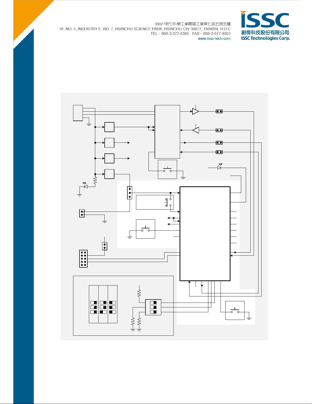
2. Block Diagram
The diagram below shows a simplified block diagram for the BM77EVB. For more detailed information please refer
to BM77EVB schematic in Appendix B, BM77EVB Schematic.
P1
USB
RED
D1
JP1
Battery Connector
(3.3V - 4.3V)
External I2C
CN2
USB-to-UART Serial Converter
MCP2200
D+
D-
U3
LDO
EXT_3V3
VDD
VUSB
U10
U5
VCC_HCI
LDO
(1.8V)
5V
U6
LDO
VCC_2V4
RESET
U1
EXT_3V7
LDO
JP2 BM77 Module
USB
VBAT
BAT
SW_BTN
SW5
[Push-On/Push-Off]
RTS
CTS
RESET
SW4
3V3
3V3
WAKE-UP
SW3
1V8
JP10
TX
RX
VCC_HCI
VCC_2V4/
EXT_3V3
U8/U9
BAT_IN
SW_BTN
LDO33_O
VDD_IO
LDO18_O
WAKEUP
PMULDO_O
P04
P15
P12/SCL
P13/SDA
U11
JP6
M_RX U_RX
JP5
M_TX U_TX
JP9
M_RTS U_CTS
JP7
M_CTS U_RTS
LED1
BLUE
3V3
External Antenna
(03 Option Only) BT_RF
LED1
P37
P36
P34
P33
P32
P31
TXD
RXD
MODE
APP
EAN
P24
P20
ON
ON
© 2014 ISSC Technologies Corp.
System Configuration
TEST
WRITE
FLASH
123
ON
3V3
UART_CTS/P17
SW1
EAN
P24
P20
123
ON
BM77 EVB BLOCK DIAGRAM
P05
UART_RTS/P00
P24
EAN
RST_N
P20
RESET
SW2
Last Revised: 2014-08-24 SB
5

3. Interface Description
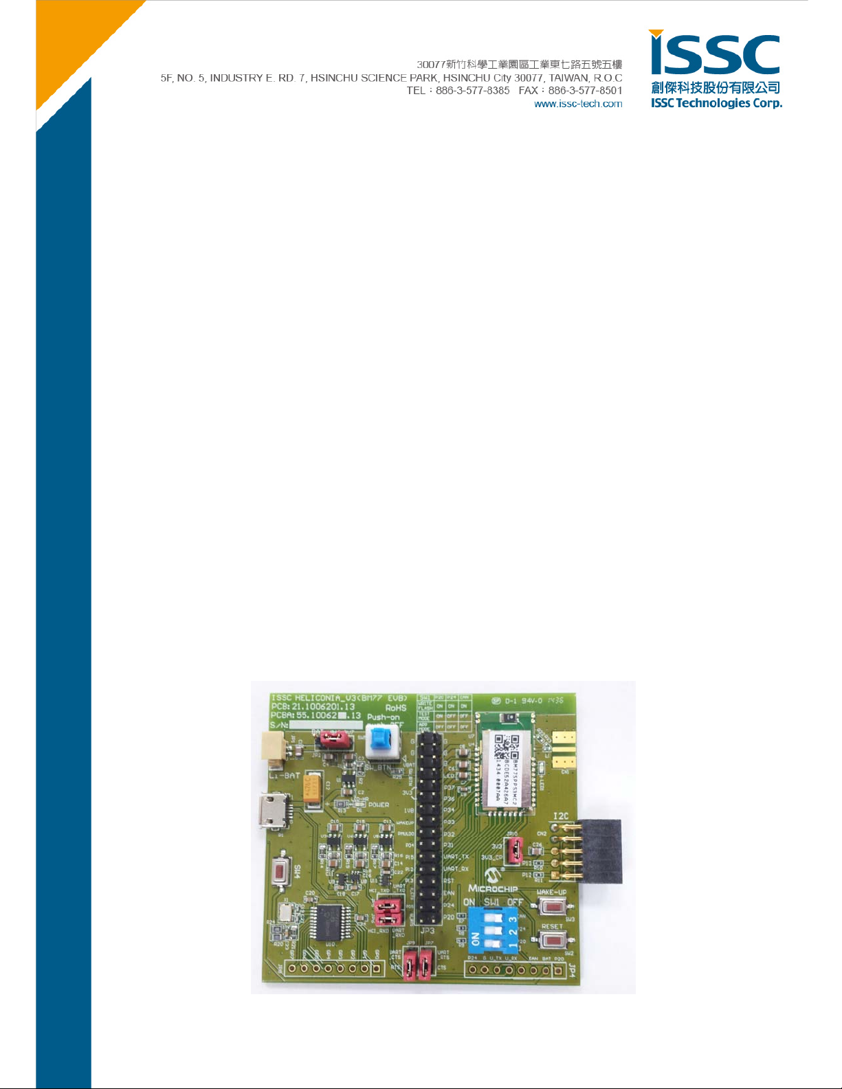
The illustration below shows a BM77EVB in its default configuration as shipped.
Description
1. JP1- Battery connector for Li-lon Battery, Voltage range 4.2~3.3V
2. JP2- Power source jumper
Source from BAT (4.2V~3.3)
Source from USB
(5V->LDO->3.7V)
3. SW5- The path between SW _BTN & BAT_IN, the bu t t o n mu s t be pr essed down to make BM77 wo rk .
4. JP3- Module 32-PIN out for connecting BM77 module to MCU
5. Bluetooth Module- BM77
6. I2C expansion port
7. I2C power jumper
8. SW3- Wake up button to wake up module from shutdown s tate
© 2014 ISSC Technologies Corp.
6
9. SW2- Reset button for Bluetooth module
10. JP4- Connect with iSSC propriety 8 PIN connector (EDGAR). Use Li-lon battery power and switch SW1
OFF while using EDGAR.
11. SW1- Mode Switch (see 3.2 Mode Definition, 3.3 Mode Settings)
12. JP7- CTS path of UART between BM77 & MCP2200. Remove the jumper if not using flow control.
13. JP9- RTS path of UART between BM7 7 & MCP2200. Remove the jumper if not using flow cont rol.
14. JP6- RX path of UART between BM77 & MCP2200. Remove the jumper if trying to connect MCU & BM77.
15. JP5- TX path of UART between BM77 & MCP2200. Remove the jumper if trying to connect MCU & BM77.
16. U10- Microchip MC P2200 chip, USB/UART converter.
17. JP8- All the GPIO PIN connected to Microchip MCP2200.
18. SW4- Reset button for Microchip MCP2200
19. USB Connector- Micro USB connector
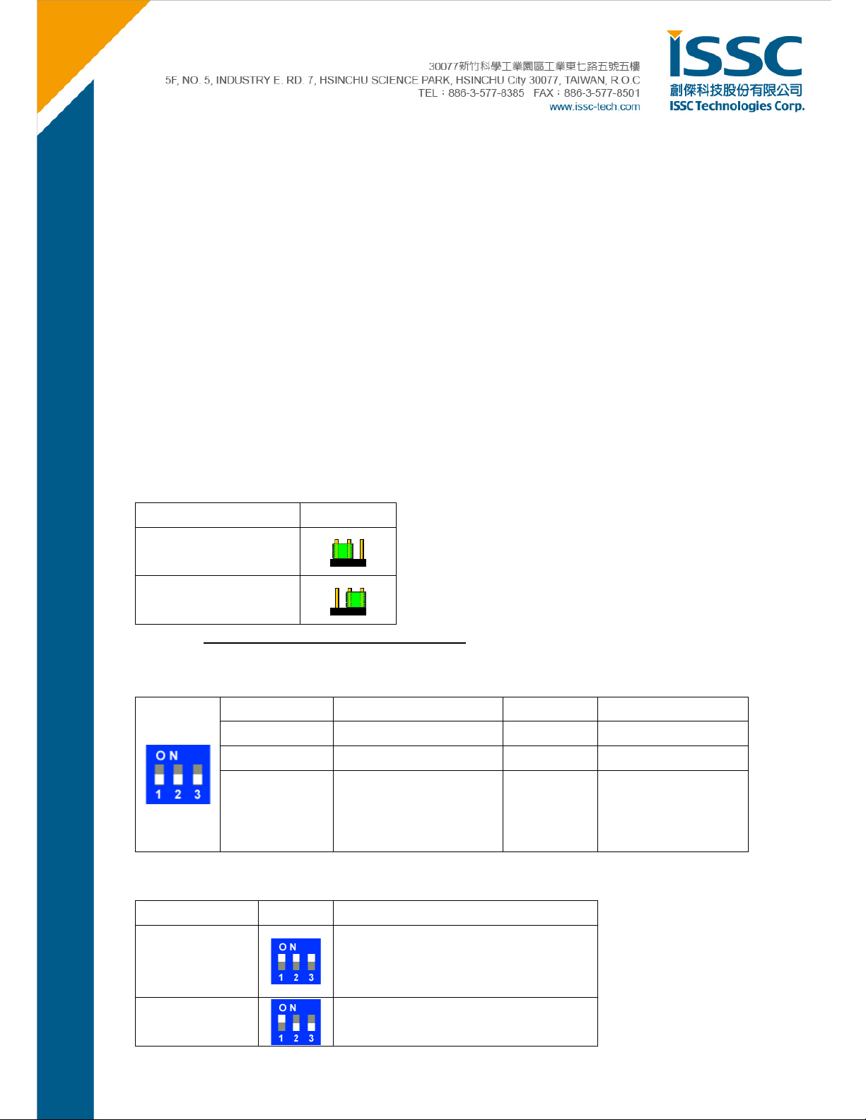
3.1. Power Switch Settings
Mode JP2
USB 5V
BAT 4.2V~3.3V
* Notice: SW5 button must be pressed down to wake BM77.
3.2. Mode Definitions
Switch Number
Pin
ON
Function
Test Mode
High=Disable/ Application
Low=Enable/ Test Mode
1 2 3
P20 P24 EAN
Low Low High
3.3. Mode Switch Settings
Flash Write
High=Disable
Low=Enable
Boot by Flas h or ROM
High=ROM
Low=Flash
Mode Switch PIN Definition
Write Flash
Test Mode
(Write EEPROM)
© 2014 ISSC Technologies Corp.
1. P20: Low
2. P24: Low
3. EAN: High
1. P20: Low
2. P24: High
7

3. EAN: Low
Application
(default)
1. P20: High
2. P24: High
3. EAN: Low
© 2014 ISSC Technologies Corp.
8

4. Quick Start Guide to Using the BM77EVB
The following sections describe how to establish Bluetooth serial data connections using the BM77EVB. The
purpose of the exercise is to d emonstra te th e ba sic d at a cap ab ilities of the BM77EVB, an d interoperability w ith other
Bluetooth devices. Please note that in all these demonstrations, the BM77EVB is a Bluetooth slave waiting for a
connection initiated by the Bluetooth master device.
For this demonstration, the following hardware and software is required:
Required Hardware:
BM77EVB Evaluation Kit, p/n EV77SPPS3MC2A available on www.microchipdirect.com
Bluetooth enabled Smartphone or Tablet
o Android device runn ing Android 4.3 or later
o iOS: iPhone 4S or later, iPad3 or later, must support Bluetooth Low Energy
Windows Host PC with USB port
Required Software:
The software applications needed to demonstrate the BM77EVB is show below:
BT Chat Tool, “BT Chat v004.exe” available at www.microchip.com/BM77
Android Chat Too l, “BTChat_V1.0.3.apk” available www.microchip.com/BM77
iOS Terminal “BLETR”, available on Apple AppStore™
MCP2200 dri ver for Windows, available at www.microchip.com/MCP2200
4.1. Bluetooth SPP connection to Android Smartphone/Tablet
In this demonstration a Bluetooth (SPP) data connection will be established between the BT Chat Tool, across
BM77EVB to the Smartphone application. For the SPP demonstration an Android 4.3 or later smartphone or
tablet is required.
As illustrated below, the host PC runs a BT Chat Tool application, which transfers serial data over a COM port (USB
virtual COM port) to BM77EVB, where it is transmitted over a Bluetooth connection to the remote Bluetooth host,
which is this example is a Smartphone application.
© 2014 ISSC Technologies Corp.
9
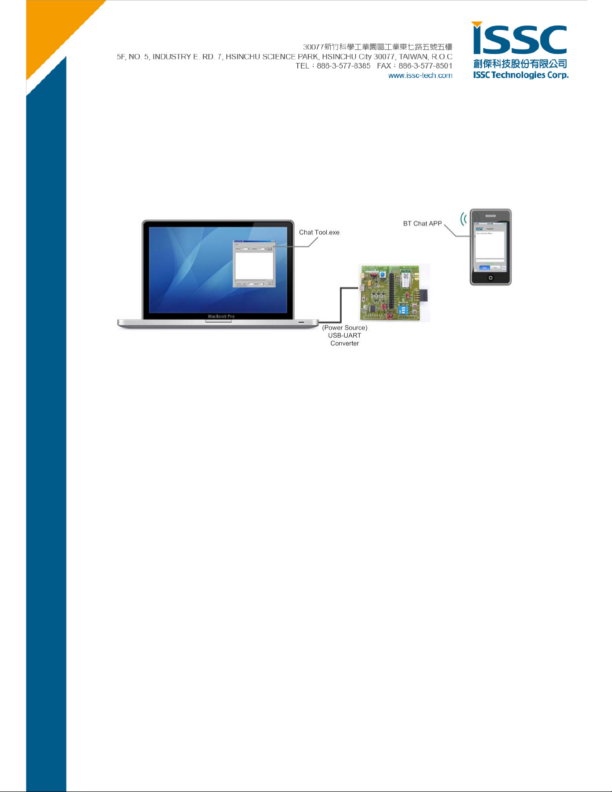
Step 1. Verify JP2 is configured for USB power.
Default is using USB as the main power supply.
Step 2. Verify SW1 switches are set to Application mode.
Make sure the SW1 is under the Application Mode. 1: OFF, 2: OFF, 3: OFF
Step 3. Verify SW5 button is in the ON (pushed down).
Step 4. Using the micro USB cable, connect the BM77EVB to host PC USB port to power up EVB.
The blue connection LED1 indicates connection state as follows:
Stand-by State- the LED1 of EVB will blink once at a time. (Blue)
Pairing, Connected State- the LED01 will blink twice at a time.
Step 5. Verify Virtual COM port is created
If a virtual COM is not observed in the Device Manag er port list, it may be necessary to install Microchip
MCP2200 driver. (Search Internet by typing keyword”
Microchi p MCP2200 Driver”)
Step 6. Run the BT Chat Tool.exe on your PC and make sure the COM Port is connected.
© 2014 ISSC Technologies Corp.
10

a. Select the COM Port assigned to the BM77EVB
b. Verify default BaudRate is 115200
c. Click Connect button.
d. The Connect button will change into a Disconnect button after connected.
Text box to enter characters to transmit.
e.
f.
Click Send to transmit text is to SmartPhone over BM77EVB Bluetooth connection.
© 2014 ISSC Technologies Corp.
11

g. The Black text are sent from PC tool (Bluetooth EVB)
h. The Red texts are sent from smart phone
i. Click the check box of Burst Send will be continuous to send text from this tool.
j. Repeat column means the how many times these texts will be resend.
Interval means the interval between two records.
k.
l. Clear button will clear up the texts on the screen.
Step 7. Install the Android BT Chat APP on the Android device.
The installation is performed by copying or downloading the “BTChat_V1.0.3.apk” file onto the Android device. The
APK file can be copied onto Android device by using an SD Card to transfer file, or plugging Android device into host
PC where Android device mounts as external USB drive (Android MTP is required on host). Once the APK file
copied onto Android device, follow the instructions below.
a. As shown below in left illustration, use and opening from file from Android File Manager “My Files” App. It
may be necessary to enable the “Unknown Sources” in Device Security settings.
b. After successful install, the BtChat APP is displayed in Application view
a b
© 2014 ISSC Technologies Corp.
12

Step 8. Pairing the BM77EVB to the Android Device
Open Settings/ Bluetooth page and ON the Turn On Bluetooth.
a.
b. Press Scan the button in step 2 to initiate the Bluetooth Device scan
c. Find the BM77EVB device named “Dual-SPP” and select it to start the pairing process.
d. Once paired, the Dual-SPP (BM77EVB) device will be listed in paired device list.
a
d
c
b
© 2014 ISSC Technologies Corp.
13

Step 9. Launch the BtChat APP on Android Device
a. BT Chat APP main window is displayed.
b. Us e the Android menu button to open BT Chat menu options. Select the “Setting” button to open APP
setting view.
c. Enable the “Show Rx Text” options. Press the “Back” button to return to main window.
a b c
© 2014 ISSC Technologies Corp.
14

Step 10. Setting up Bluetooth SPP connection to the BM77EVB device
a. From BT Chat APP main window, pre ss the Android menu button to open BT Chat menu options. Select the
“Connect a device” button to open pai red device list .
b. Select the “Dual-SPP” device to open an SPP connection to BM77EVB.
c. After connection is established the status message is displayed in main window.
b
a
c
© 2014 ISSC Technologies Corp.
15

Step 11. Transferring data from BM77 to Android Device via Bluetooth SPP connection
Launch the Bluetooth Chat application on host PC tool and set the correct COM port corresponding to the
BM77EVB.
a. Enter text to send in BTChat Android APP
b. C lick “Send” to transmit text to BM77 connected to Bluetooth Chat on PC
c. Observe received text in red font color on Bluetooth Chat PC
d. Enter enter text to send in Bluetooth Chat PC
e. Click “Send” to t ransmit text to Android BTCha t Android APP
f. Observe received text in BTChat Android APP
c
d e
f
a b
© 2014 ISSC Technologies Corp.
16

4.2. Bluetooth Low Energy Data Connection to iOS Device
This demonstration show how serial data is transmitted from BM77EVB (via PC Chat) to an iOS devic e using
Bluetooth Low Energy connection. This demonstration uses ISSC BLETR APP to connection to the BM77EVB.
Bluetooth Low Energy is utilized since iOS devices do not support Bluetooth Classic SPP data connections. A key
feature of the BM77 is transparent serial data connection from BM77 UART to an iOS device.
a. Using an iPhone 4S or later, iPad3 or later device, download and install “ISSC BLETR” APP . As illustrated
below, the BLETR App is available on the AppStore.
© 2014 ISSC Technologies Corp.
17

b. Turn on the Bluetooth radio in iPhone, iPod or iPad Settings application.
c. Go to Settings/ General/ Bluetooth Page.
d. Turn ON the Bluetooth.
e. Launch the iSSC BLETR APP and it will scan th e Bluetooth Low Energy Peripheral devices and list them. If
the device does not appear press the “Refresh” button to res tart the BTLE peripheral scan. Find the
Dual-SPP BTLE peripheral device. Select it to start a connection to the BM77EVB named Dual-SPP.
f. After a successful connection to BM77EVB, BLETR will display the device as connected as shown below.
© 2014 ISSC Technologies Corp.
18

g. Select the connected Dual-SPP device to display the top level view. This view presents three options when
connected to a BM77EVB.
Transparent - View to display received data, send data, and enable features
Proprietary- This view sets Bluetooth Low Energy connection parameters
Device Info -This view displays the settings for Bluetooth Low Energy Device Information Service
© 2014 ISSC Technologies Corp.
19

h. Selecting “Transparent” button opens the transparent Serial Dat a view as shown below. The default mode is
Raw (ASCII) mode where any data characters received are displayed in the large text box in red font.
Data Mode Transfer
© 2014 ISSC Technologies Corp.
20

To send data from BLETR iOS device to the BM77, select the input text box. The soft keyboard will be displayed as
shown below. Enter text in the input text box. Click “Send” button to transmit text to BM77.
After clicking “Send” the text is received via the BM77 UART and displayed in the BT CHAT text window.
© 2014 ISSC Technologies Corp.
21

Timer Feature
In addition to Raw mode (ASCII) the Transparent data view als o has Timer and Echo features. The Timer feature
allows the BLETR to send a repeated test pattern to BT CHAT for test throughput and data transfer test.
An example of the “Timer” test feature is shown below.
BLETR configured to transmit a 100 test blocks of 20 characters, every 1000ms. BT CHAT tool receives the test
pattern data and di splays it in red text. The line break indicates a Bluetooth Low Energy packet break, meaning a
transmittted test block was fragmented into multiple BLE packets.
Clicking the “Start” button initiates the data transfer.
© 2014 ISSC Technologies Corp.
22

Tx File Feature
Another test feature similar to the Time r feature is the “TX File” tra nsfer. The “TX File” functions transfers files, which
as embedded in the BLETR APP, to the BM77. The steps to use this feature are as follows:
a. Click the “TX File” button to open a dialog with list of file sizes to transmit
b. Select the file size to send
c. Observe the file received on BT Chat.
c
b
a
© 2014 ISSC Technologies Corp.
23

Echo Feature
The Echo feature is an optional function for the Transparent data view. When Echo is enabled, any data rece ived by
BLETR is echoed back to sender.
The example below show text sent from BTCHAT being echoed to BLETR when the Echo mode is enabled.
© 2014 ISSC Technologies Corp.
24

Device Information Feature
The Device Information view displays the characteristics associated with Device Information service. The Device
Information service is available to all Bluetooth 4.0 low energy host that access the BM77EVB. It exposes the
information identifying information about the BM77 peripheral device. These values can be programmed using a
configuration tool descr ibed in the application note.
© 2014 ISSC Technologies Corp.
25

Proprietary (Configuration) Feature
The Proprietary view demonstrates the capability to change Bluetooth Low Energy connection parameters remotely
via BLETR application. These parameters only affect Bluetooth Low Energy connections.
1. Max Interval: time (ms) between communication interval between BM77 and Bluetooth LE Central device.
2. Connection Timeout: time (ms) between communication events before a connections considered lost
3. Latency: Number of connection events peripheral (BM77) is allowed to skip
4. Bluetooth LE Name used to advertise Peripheral name to scanning Central devices. Enter new name in text
box and click “Change Name” to invoke change.
© 2014 ISSC Technologies Corp.
26

5. Appendix A: BM77SPP03 Module PIN Assignment
U4
1
GND
BAT_IN
SW_BTN
WAKEUP
PMULDO_O P32
P04
P15
P12/SCL
P13/SDA
2
BAT_IN
3
SW_BTN
4
LDO33_O
5
VDD_IO
6
LDO18_O
7
WAKEUP_SI1
8
PMULDO_O
9
P04
10
P15
11
P12 / SCL
12
P13 / SDA
P17
1314151617
P05
UART_CTS / P17
P0_5/TX_CLS1
UART_RTS / P00
P00
P20
P20
P24
BT_RF
GND
LED1
P37
P36
P34/SCLK
P33/MOSI
P32/MISO
P31/NCS
HCI_TXD
HCI_RXD
RST_N
P2_4/RX_CLS1
EAN
18
EAN
30
29
28
27
26
25
24
23
22
21
20
19
BT_RF1
UART_TXD
UART_RXD
RST_N
BM77 Module PIN Define
P/N I/O Name Description
1 P GND Ground
LED
P37
P36
P34
P33
P31
2 P BAT_IN 4.2~3.3V Power input
Input for software button.
3 I SW_BTN
H: Power On
L: Power Off
4 P LDO33_O 3V3 LDO output
5 P VDD_IO Main power supply
6 P LDO18_O LDO18 output
Wakeup BM77 from Shutdown State. (Low Active)
7 I WAKEUP
It is only valid while BM77 into Shutdown State.
8 P PMULDO_O Output of PMULDO
UART_TX_IND:
H: BM77 indicate UART data will be transmitted out after a certain ti ming.
(Setting by EEPROM, default 5ms)
9 O P04
L: Otherwise.
STATUS_IND_2:
BM77 State indication , refer to P15
© 2014 ISSC Technologies Corp.
27

P/N I/O Name Description
STATUS_IND:
Bluetooth link status indicat i o n
10 O P15
11 N/A P12/ SCL I2C_SCL, Reserved
12 N/A P13/ SDA I2C_SDA, Reserved
P15/P04: HH Power default value and Shutdown State.
P15/P04: HL Access State.
P15/P04: LL Link State w/o UART_TXD.
P15/P04: LH Link State with UA RT_TXD.
13 I
P17
- UART_CTS:
- Configurable Functional GPIO
14 I/O
15 O
P05
P00
Configurable Functional GPIO
- UART_RTS
- Configurable Functional GPIO
16 I P20 System configuration, refer to P2_4. (No drive under APP Mode)
Boot mode selection. (No drive under APP Mode)
17 I P24
18 I EAN
19 I RST_N External reset input (Low Active), Clock period 62.5n at least
20 I HCI_RXD UART_RXD
21 O HCI_TXD UART_TXD
22 I/O
P31
P2_0/ P2_4: HH Application
LL Boot mode
LH HCI UART mode for testing and system configuration.
ROM/Flash selection. (No drive under APP Mode)
H: ROM code; L: Flash code
Configurable Functional GPIO
23 I
24 I
25 I
26 O P36 Reserved
27 I/O
28 O LED1 LED1 driver
29 P GND Ground
30 RI/O BT_RF RF Port
© 2014 ISSC Technologies Corp.
P32
P33
P34
P37
Configurable Functional GPIO
Configurable Functional GPIO
Configurable Functional GPIO
Configurable Functional GPIO
28

6. Appendix B: BM77EVB Schematic
P1
6
78
VBUS
1
D-
2
D+
3
ID
4
GND
5
9
USBM3121-051-1-BN-R
HCI_TXD
2
1
JP5
JP 1x2
UART_TXD
RX
U8
1
A
VCC
2
B
3 4
GND Y
SN74AHC1G08DCK
1
2
3 4
D-
D+
VCC_2V4
C17
0.1u/16V
5
U9
1
2
3 4
SN74AHC1G08DCK
VCC_HCI
U11
SN74AHC1G08DCK
A
VCC
B
GND Y
5
L e ve l S h ift
5V
12
C12
47u/16V
EXT_3V3
C18
0.1u/16V
5
A
VCC
B
GND Y
C22
0.1u/16V
HCI_RXD UART_RXD
JP6
JP 1x2
TX
1
2
D1
LED-HR
R13
1K
12
12
12
R8
4K7
5V
1
2
3
JP2
JP 1x3
FOR CURRENT
MEASUREMENT
12
R9
4K7
C2
10u/16V
BAT_ON
BAT
EXT_3V7
USB_O N
3V3
C10
10u/16V
C13
10u/16V
C15
10u/16V
R7
10
1
2
3 4
U1
RT9179PB
10u/16V
C4
6
12
5
4
ON
SW1
SW-3BIT
VIN
VOUT
GND
EN ADJ
VBAT
1
2
1
2
1
2
JP4
JP 1x8
VIN
GND
EN3ADJ
U3
RT9179PB
VIN
GND
EN3ADJ
U5
RT9179PB
VIN
GND
EN3ADJ
U6
RT9179PB
3
2
1
5
1
2
3
4
5
6
7
8
VOUT
VOUT
VOUT
5
4
30K/1%
5
4
30K/1%
5
30K/1%
4
30K/1%
EAN
P24
P20
12
R1
68K
12
R2
30K/1%
UART_RXD
UART_TXD
P20
EAN
P24
R12
56K
R14
R16
18K
R17
R18
R19
12
10u/16V
12
12
10u/16V
12
12
10u/16V
12
EXT_3V7
EXT_3V3
C11
VCC_HCI
C14
VCC_2V4
C16
C3
10u/16V
BAT
© 2014 ISSC Technologies Corp.
29

WAKEUP
10u/16V
C23
0.1u/16V
RTS
JP9
JP 1x2
1
UART_CTS / P17
2
CTS
WAKE-UP RESET
X1
X4P-12MHZ
3
2
RST_N
JP8
JP 1x8
BAT
C1
EXT_3V3
12
R20
10K
SW3
CTT-1131U
R24
1K
21
2
1
12
JP1
SJP 1x 2
3 4
C21
12p/50V
1 2
R21
470
4
1
1
2
3
4
5
6
7
8
EXT_3V3
C19
12p/50V
GP7
GP6
GP5
GP4
GP3
RX
UART_RTS / P00
1
2
JP7
JP 1x2
21
SW2
CTT-1131U
GP0
GP1
GP2
GP3
GP4
GP5
GP6
GP7
C20
0.1u/16V
1
VDD
2
OSC1
3
OSC2
4
RST
5
GP7/TxLED
6
GP6/RxLED
7
GP5
8
GP4
9
GP3
10 11
TX RTS
MCP2200
VBAT
3V3
1V8
VSS
VUSB
GP0/SSPND
GP1/USBCFG
GP2
CTS
SW_BTN
WAKEUP
PMULDO_O
P04
P15
P12/SCL
P13/SDA
UART_CTS / P17
P05
UART_RTS / P00
SW5
4
5
6
20
19
D+
18
D-
17
16
15
14
13
12
RX
U10
4
5
6
GP0
GP1
GP2
CTS
TX
RTS
1 2
3 4
5 6
7 8
9 10
11 12
13 14
15 16
17 18
19 20
21 22
23 24
25 26
27 28
29 30
31 32
PS-5177
D-
JP3
JP 2x16
EXT_3V3D+
1
1
2
2
3
3
C24
0.1u/16V
LED
P37
P36
P34
P33
P32
P31
UART_TXD
UART_RXD
RST_N
EAN
P24
P20
R25
3K
1 2
SW_BTN
VBAT
21
SW4
CTT-1131U
VBAT
C5
10u/16V
3V3
C6
10u/16V
1V8
C7
10u/16V
1u/16V
© 2014 ISSC Technologies Corp.
3
2
1
CN1
SMA8401
4
5
U4
1
GND
BAT_IN
SW_BTN
WAKEUP
PMULDO_O
P04
P15
C8
P13/SDA
2
BAT_IN
3
SW_BTN
4
LDO33_O
5
VDD_IO
6
LDO18_O
7
WAKEUP_SI1
8
PMULDO_O
9
P04
10
P15
11
P12 / SCL
12
P13 / SDA
P17
P0_5/TX_CLS1
P00
1314151617
P05
P20
UART_CTS / P17
UART_RTS / P00
P34/SCLK
P33/MOSI
P32/MISO
HCI_RXD
P20
P2_4/RX_CLS1
P24
BT_RF
GND
LED1
P37
P36
P31/NCS
HCI_TXD
RST_N
EAN
18
EAN
30
29
28
27
26
25
24
23
22
21
20
19
BT_RF1
LED
P37
P36
P34
P33
P32
P31
UART_TXD
UART_RXDP12/SCL
RST_N
L1
1nH
LED1
LED-B
RF
12
3V3
30

VBAT
3V3
1V8
BAT_IN
SW_BTN
WAKEUP
PMULDO_O
P04
P15
P12/SCL
P13/SDA
FP-BM77SPPA
U7
1
G
2
G
3
GND
4
BAT_IN
5
SW_BTN
6
LDO33_O
7
VDD_IO
8
LDO18_O
9
WAKEUP_SI1
10
PMULDO_O
11
P04
12
P15
13
P12 / SC L
14
P13 / SD A
P34/SCLK
P33/MOSI
P32/MISO
P31/NCS
HCI_TXD
HCI_RXD
P1715P0_5/TX_CLS116P0017P2018P2_4/RX_CLS119EAN20RST_N
21
EAN
P20
P05
P24
RST_N
GND
LED1
P37
P36
33
G
32
G
31
30
LED
29
28
27
26
25
24
23
22
P37
P36
P34
P33
P32
P31
UART_TXD
UART_RXD
C26
10u/16V
3V3_CP
1
JP10
JP 1x2
UART_RTS / P00
UART_CTS / P17
3V3
P12/SCL
2
P13/SDA
R11
1 2
2K2/1%
R10
2K2/1%
3V3_CP
12
3V3_CP
3V3_CP
CN2
9 10
P13/SDA
P12/SCL
APPLE CP connect
7 8
5 6
3 4
1 2
SSQ-F-2x5-R
P36
© 2014 ISSC Technologies Corp.
31

7. Appendix C: Q & A
1. Is the BM77 Module Data Sheet available?
Yes. Contact your Microchip representative to request additional information about the BM77 module.
2. When I connect the BM77EVB to the host PC the COM port does not appear?
Try resetting the MCP2200 by pressing SW4.
3. What is maximum supported baud rate of BM77 UART?
The maximum baud rate is 921600 with used with of 16MHz crystal.
4. How do you change Bluetooth parameters such name, Device Info, COD, rate, inqu iry and pa ge scan w indows?
The configuration settings are accessed using a “UI Tool” software utility. Contact your Microchip representative
to request additional configuration tools and documentation for BM77.
5. What is default security mode for SPP?
SSP/It Just Works
6. Is there an Android BTLE demonstration application?
At this time Android support for dual-mode Bluetooth devices, such as the BM77, is limited to Bluetooth classic
SPP data service.
7. Is the source code for iOS and Android APP available
Contact your Microchip representative to request the source code packages for the smartphone Apps.
© 2014 ISSC Technologies Corp.
32

8. Appendix D: Revision History
Version Date History
0.1 2012/8/27 Draft Version
0.2 2014/06/12 Modify connect with Ipad air tool
0.3 2014/07/30 Modify layout
0.4 2014/10/03 Added screen shots for Smartphone Apps, revisions for MCHP BM77EVB release
© 2014 ISSC Technologies Corp.
33
 Loading...