

Ispring RCC7, RCC7AK, RCC7P-AK, RCC7AK-UV, RCC7D Installation Instructions & Owner's Manual
...
iSpring Reverse Osmosis Water Filtration
Systems
INSTALLATION INSTRUCTIONS
& OWNER’S MANUAL
Ver. 11/2018
Copyright ©2005-2017 ISPRING WATER SYSTEMS, LLC. All rights reserved.

We stand behind our products
iSpring has been dedicated to providing high quality drinking water to families across the United
States since 2005.
From various residential water filtration systems that purify your water in everyday life, to drinking
water faucets that deliver pure, healthy, and tasty water to you and your family, iSpring strives for
high standard products and aims to make excellent drinking water accessible for all households.
At iSpring, we strive for high standard products and aim to make excellent drinking water
accessible for all households.
With affordable pricing, solid quality, prompt delivery, and top-notch customer service, we hope to
assist in bringing you great water for years to come.
Page 1www.123filter.com | (678) 261-7611 | Support@123Filter.com

Table of Contents
System Installation
Prior to Installation ................................................................................................. 3
Component Identification ....................................................................................... 4
Installation Tips ...................................................................................................... 5
Installation Steps ..................................................................................................... 7
Step 1: Installing the Feed Water Adapter ............................................................. 7
Step 2: Installing the RO Faucet ............................................................................. 8
Step 3: Installing the Drain Saddle ......................................................................... 8
Step 4: Installing the Vertical Filters: Stages 1, 2, and 3 ....................................... 9
Step 5: Installing theTank Shut-Off Valve ............................................................. 9
Step 6: Installing the Reverse Osmosis Membrane ................................................ 9
Step 7: Tubing Hook Up ....................................................................................... 10
Step 8: System Start Up ........................................................................................ 12
Leak Stop Valve Installation ................................................................................ 13
Owner's Manual
Section 1: iSpring RO System Maintenance ........................................................ 14
Section 2: Knowledge Base and FAQ .................................................................. 17
Section 3: Troubleshooting Guide for Newly Installed Systems ......................... 21
Section 4: Glossary and Terms to Know .............................................................. 23
Warranty
Warranty Registration ........................................................................................... 26
Page 2www.123filter.com | (678) 261-7611 | Support@123Filter.com

System Installation
Prior to Installation
Inspect the package
Open the box and remove all of the components. Inspect them to ensure nothing was damaged
during shipping. If any part is cracked or broken, please immediately contact iSpring Customer
Support for a replacement. Identify and get familiar with the components.
Recommended tools list
● Variable speed drill with two bits: ¼” (for drilling a hole on PVC drain pipe), ½” hollow
diamond (for drilling a hole on countertop for drinking faucet)
● 5/8”, 9/16” open-end wrench, or adjustable wrench, pliers
● Phillips head screwdriver
● Scissors or utility knife
Operating conditions
● Minimum water pressure: 45 PSI, otherwise a booster pump is necessary to raise the
incoming water pressure and improve the RO efficiency.
● Maximum water pressure: 70 PSI, otherwise a pressure regulator (part no. APR70) is
required to lower the PSI to the maximum level.
● Operating water temperature range: 40 – 100 °F (4 - 37 °C) (This RO system is NOT
designed for HOT water). The RO process will be slightly faster the warmer the source
water is and vice versa.
● Maximum TDS: 750 ppm
● Install this RO system in a location where it is safe from hot/cold weather and direct
sunlight. Avoid hitting, dropping, or dragging the system as this can cause cracks and leaks.
Page 3www.123filter.com | (678) 261-7611 | Support@123Filter.com
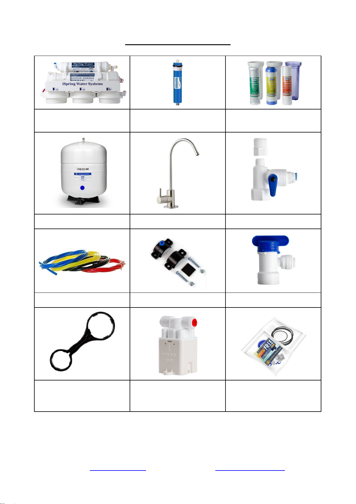
Component Identification
RO Machine Head
* (membrane not yet installed)
RO Membrane
3 Pre-Filter Housings and
Cartridges
Storage Tank
RO Faucet w/ Installation Kit
Feed Water Adapter
4-Color Tubing Set
Drain Saddle ¼”
Tank Valve
Housing Wrenches
Leak Stop Valve
Spare O-Rings and Fittings
vary)
* If your system is a 6-stage or 7-stage system with an Alkaline, DI, and / or UV filter, the 6th and
7th stages are already pre-installed on the machine head. The UV filter is typically the final stage for
all RO UV systems, but can be moved in front of the 1st stage if the incoming water is already clear.
Page 4www.123filter.com | (678) 261-7611 | Support@123Filter.com
(Real package quantity may
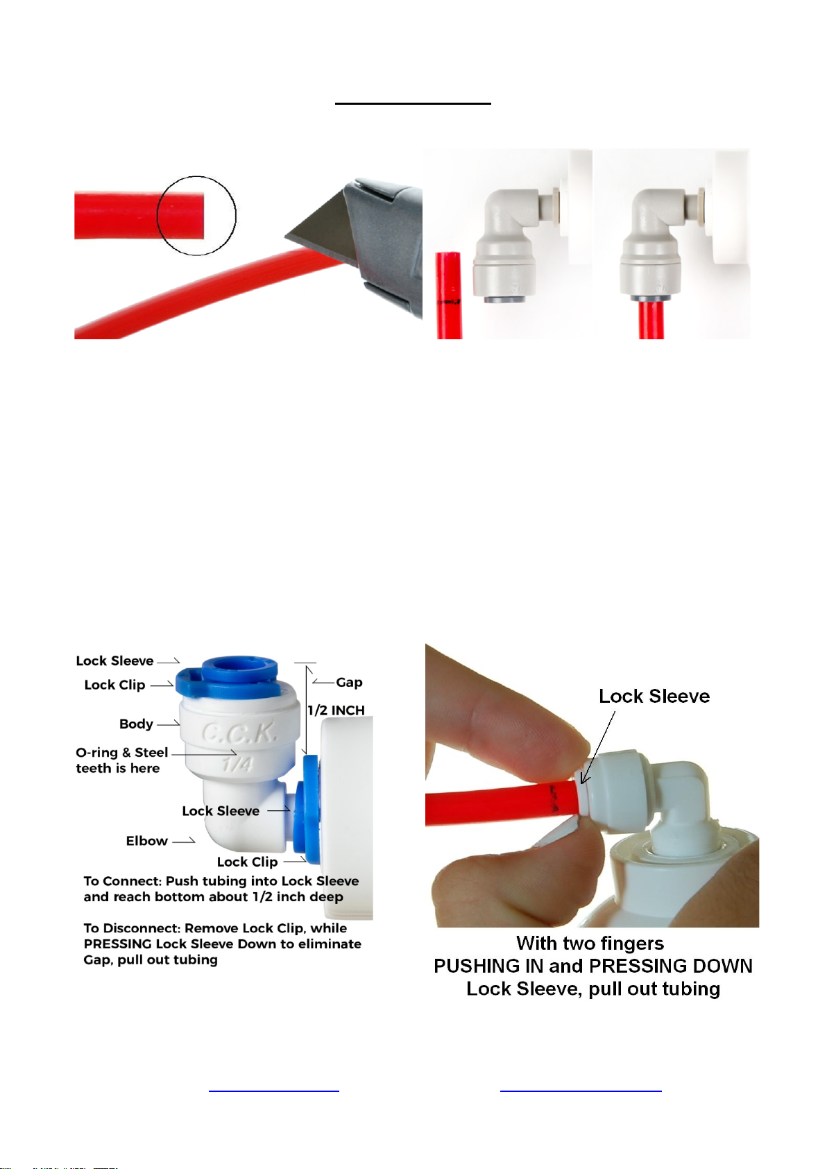
Installation Tips
Figure 1
How to use the Quick-Connect fittings
To connect:
1. See Figure 1. Check and cut the tubing end squarely and cleanly with utility knife or
scissors.
2. Make a ⅝” mark at the end of the tube so you will be able to confirm when the tube is
inserted fully into the fitting.
3. Remove the blue lock clip from the fitting with your nail. If the lock sleeve pops out of the
fitting when doing this, simply pop it back in.
4. Insert the tube into the fitting until you reach the ⅝” mark on the tube. You will feel
resistance when the tube reaches the small rubber O ring inside the fitting. You will need to
wiggle the tube and apply additional pressure to get it passed this O ring and create the seal.
If the tube is not ⅝” into the fitting and past the O ring, no seal will be created and
leaking will occur.
5. Once the tube is fully inserted into the fitting, pop the blue lock clip back on the fitting. This
will lock the tube in place and prevent it from moving.
Figure 2
Figure 3
Page 5www.123filter.com | (678) 261-7611 | Support@123Filter.com
To disconnect:
1. See Figures 2 and 3. Remove the blue lock clip from the fitting.
2. With the blue lock clip removed, use your thumb and index finger to hold down the lock
sleeve. This will release the metal teeth holding the tube in place. While holding the lock
sleeve down with that hand, use your other hand to remove the tube from the fitting.
How to drill a ½” hole in your sink or counter-top
1. It’s highly recommended to watch the YouTube video “How To Drill Faucet Holes” to
get a better understanding of the process. Depending on what kind of countertop you have,
you may want to hire an experienced professional to ensure the hole is drilled correctly.
2. Choose a half inch Diamond Core Bit for granite, and a titanium drill bit for steel. Do NOT
use a hammer drill on nature stone, glass, and ceramic.
3. An indent should be made with a punch on steel before drilling to help guide the bit.
4. Use caution when drilling on a Porcelain sink, as it could be easily chipped. Set drill speed
on slow. Press the bit downward firmly until breaking through the slippery surface. Some
people found it is easier to secure the bit by drilling through a piece of wood that is firmly
pressed on the surface.
5. Use coolant to disperse heat. Choose water for granite, and oil for steel. Use the Water
Suction Cup to hold coolant inside and prevent the drill bit from slipping.
6. Starting at slowest speed, hold the drill firmly and vertically and prevent the drill bit from
slipping on the counter.
7. Once breaking through the smooth surface, swirl the drill a little to apply pressure in a circle
evenly.
8. Be patient and deliberate. It can take 20 – 40 minutes to drill through one inch.
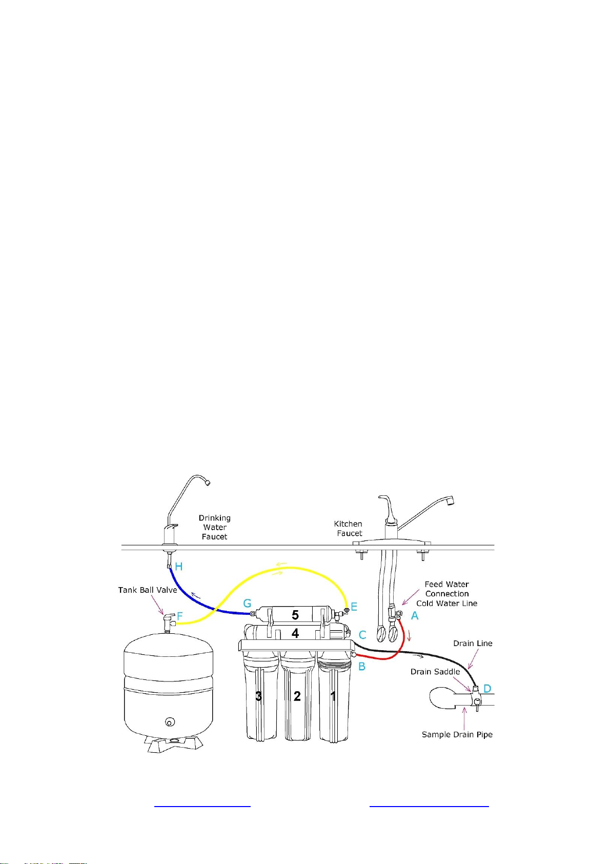
Sample Installation
Figure 4
Page 6www.123filter.com | (678) 261-7611 | Support@123Filter.com
A. Source water from Feed Water Adapter → B. Source water to 1st stage water inlet
C. Waste water from Flow Restrictor →D. Waste water to Drain Saddle/drain pipe
E. RO water from stage 5 “T” fitting → F. RO water to Storage Tank
F. When the drinking faucet is opened, RO water from the tank passes through E and G → H. RO
water to the drinking faucet
Installation Steps
Before you begin the installation, it is highly recommended that you watch the
video “iSpring Reverse Osmosis Installation” on YouTube.
Note: If you plan on mounting/hanging the system, it is highly recommended to
include supports under each of the bottom three housings. Supports under the
housings will take the water weight off the housing threads, and ensure the thread strength does not
decay over the years.
Note: Steps 1 – 7 are independent, and can be performed in any order.
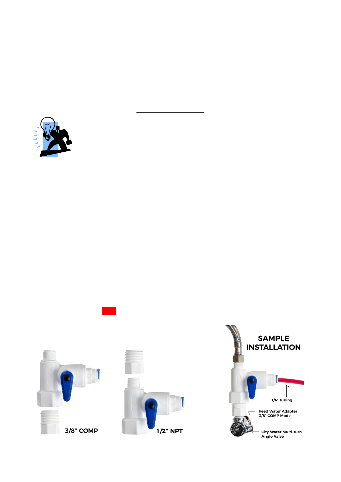
Step 1: Installing the Feed Water Adapter
(The bushing can convert 3/8” comp. to ½” NPT.)
1.1 Turn off the Cold Water Line via the Cold Water Supply Valve (CWSV) under the sink.
Open the kitchen faucet to release any pressure and make sure the water has stopped before
proceeding to the next step. Get a towel or bucket to catch any water drips. Disconnect the
Kitchen Faucet Connector (KFC) pipe from the CWSV.
1.2 Check to make sure the O-ring is seated inside the Feed Water Adapter female end, and
twist it onto the CWSV. Tighten it using a wrench or pliers.
1.3 Twist the KFC onto the male end of the Feed Water Adapter. Turn the handle of the Feed
Water Adapter to the perpendicular OFF position. Turn on the CWSV slowly, and ensure
you are getting a proper seal.
1.4 Connect the 1/4” RED tubing to the Feed Water Adapter.
Feed Water Adapter with Bushing to convert
3/8” COMP to 1/2” NPT
Page 7www.123filter.com | (678) 261-7611 | Support@123Filter.com
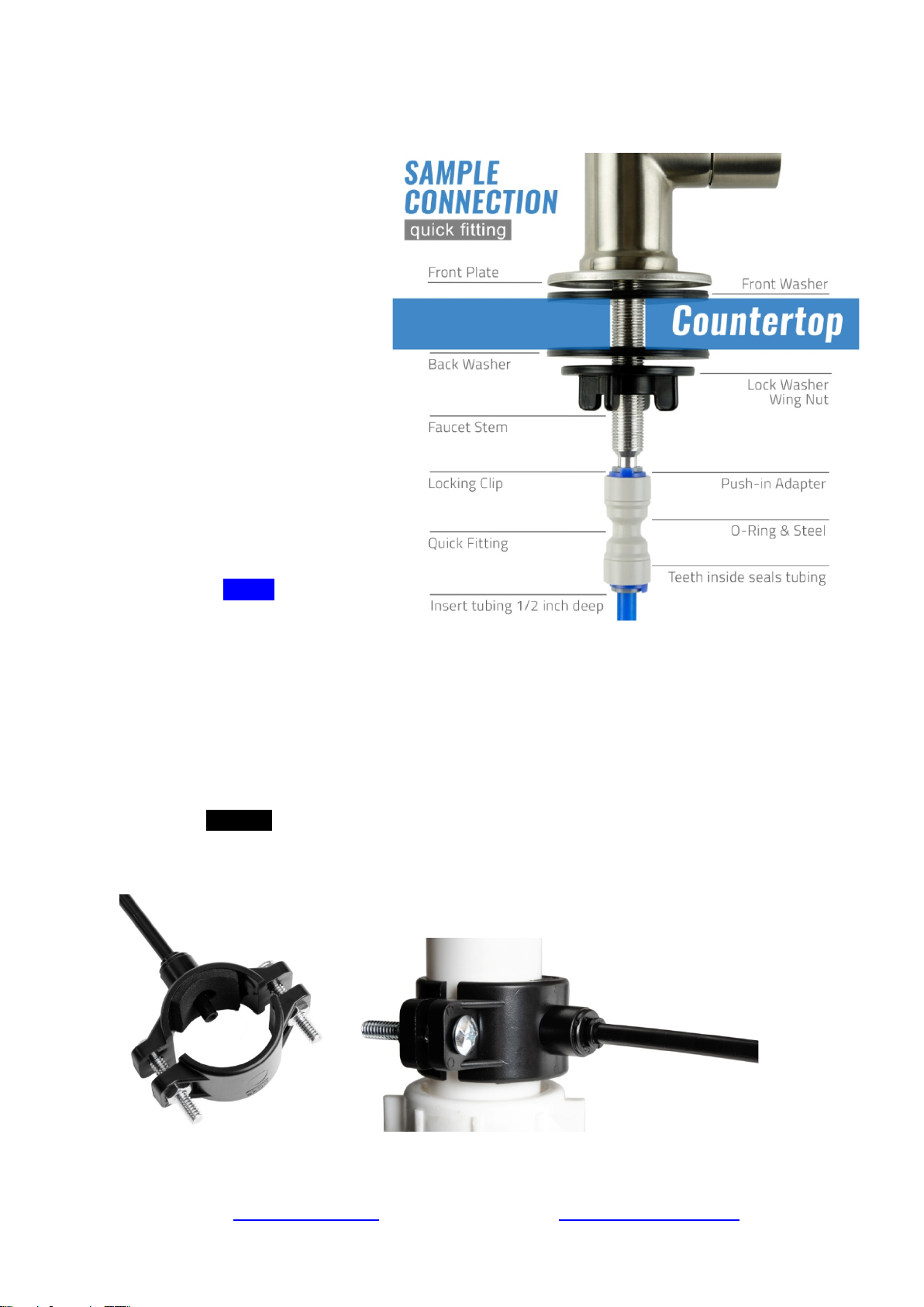
Step 2: Installing the RO Faucet
2.1 If your kitchen sink does not
have an existing ½” faucet
hole, you will have to drill one.
(Refer to How to drill a Hole
on Sink or Counter-top). Wipe
clean and dry the area.
2.2 Slip the front plate on the
faucet stem, followed by the
rubber washer. Insert the
faucet stem into the hole on
the countertop. Under the sink,
slip on the back rubber washer,
and tighten the nut with the
plastic wing.
2.3
Slide the quick connecting up
the push-in adapter on the
base so that it seats securely
into the faucet stem, then lock
it in place by sliding the blue
clip under the collet.
2.5 Insert the BLUE tubing about
1/2 inch into the push-in
and again, secure it with the
blue clip.
fitting,
Step 3: Installing the Drain Saddle
3.1 Choose a spot on the drain pipe that is convenient for installing the drain saddle and tubing.
A horizontal pipe is recommended to minimize the dripping sound.
3.2 Drill a 1 /4” hole in the drain pipe, and paste the black sticky pad around the hole.
3.3 Cut the BLACK tubing end to make a 45 degree angle. Insert the tubing into the 1/4” hole
in the drain pipe, install the back plate, and tighten the two screws with hex nuts while the
tubing remains in the hole.
3.4 Insert Lock Clip. Pull the tubing lightly to make sure it is secure.
Page 8www.123filter.com | (678) 261-7611 | Support@123Filter.com
 Loading...