

Isotra SCREEN HR7, screen HR8-ZIP Measurement And Assembly Manual

MEASUREMENT AND ASSEMBLY MANUAL
Validity of the manual: 1. 6. 2017
1
SCREEN HR7, HR8-ZIP
1. LIST OF REQUIRED TOOLS
•
Ladder
•
Dril
•
Crosshead screwdrivers
•
Set of metal dril bits
•
Masonry dril bits (6 mm and 8 m)
•
Set of Allen keys
•
Pop rivet tool
•
Tape measure and pencil
•
Spirit level, plumb line and hose level
•
Voltmeter or test lamp 220 V
•
Test cable with switch
•
Silicon caulk or joint sealing strip
2. ASSEMBLY
2.1. CHECK THE PROVIDED PARTS
Check the provided parts and open the bag containing the fittings. Divide the screws, plugs, washers and caps equally
between the guide rails. You should have an equal amount of fastening material for each guide rail.
2.2. CHECK THE HEIGHT AND WIDTH
Measure the width of the screen box and the window opening, then determine whether the box is the right size for the
installation situation.
Also check the height from the top of the box to the bottom of the guide rails, including the end stops.
Measure the inside height of the window frame. Check whether they match, taking the mounting bracket into account.
MEASUREMENT AND ASSEMBLY MANUAL
Validity of the manual: 1. 6. 2017
2
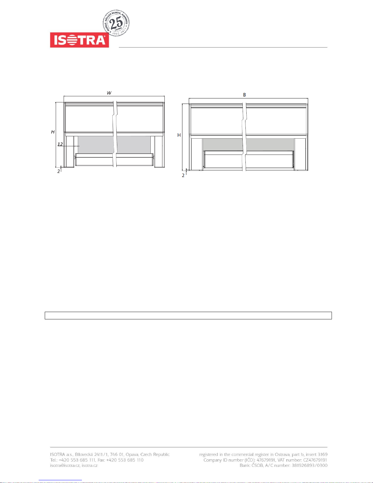
HR7: HR8-ZIP:
fig. 1
Final width B = the distance between the end brackets.
Final height H = the height including box and guide rail ends (thickness = 2 mm) except the mounting bracket.
Note: the final height H with steel cable from the top edge of the box to the lower side of the bottom rail.
2.3. DRILL THE HOLE FOR THE LEAD-THROUGH
Measure the position of the control lead-through on the screen box. Mark this on the window frame.
Drill the hole for the control lead-through through the window frame:
For motorised operation use a 10 mm drill bit; see fig. 3 on page 3.
For crank handle operation use a 14 mm drill bit; see fig. 2 on page 3.
For exterior crank handle operation with eye you do not have to drill a lead-though.
Attention! Do not drill into the window glass.

MEASUREMENT AND ASSEMBLY MANUAL
Validity of the manual: 1. 6. 2017
3
2.3.1. OPERATING EXITS FOR HANDLE
rod 90° rod 90° rod 90° rod 90°
exit A exit B exit O exit K
2.3.2. MOTOR EXITS
fig. 2
fig. 3
MEASUREMENT AND ASSEMBLY MANUAL
Validity of the manual: 1. 6. 2017
4
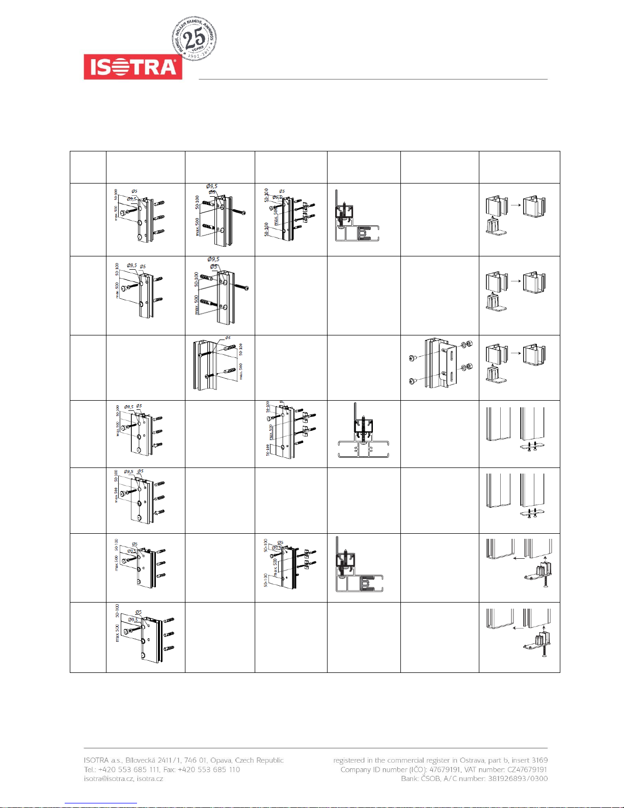
2.4. PRE-DRILLING THE GUIDE RAILS
Guide
rail
Drilling on the
side
Drilling in the
back
Clip mounting*
Sealing
strips**
Distance
support***
End stop****
725
720
728
755
756
829
820
MEASUREMENT AND ASSEMBLY MANUAL
Validity of the manual: 1. 6. 2017
5
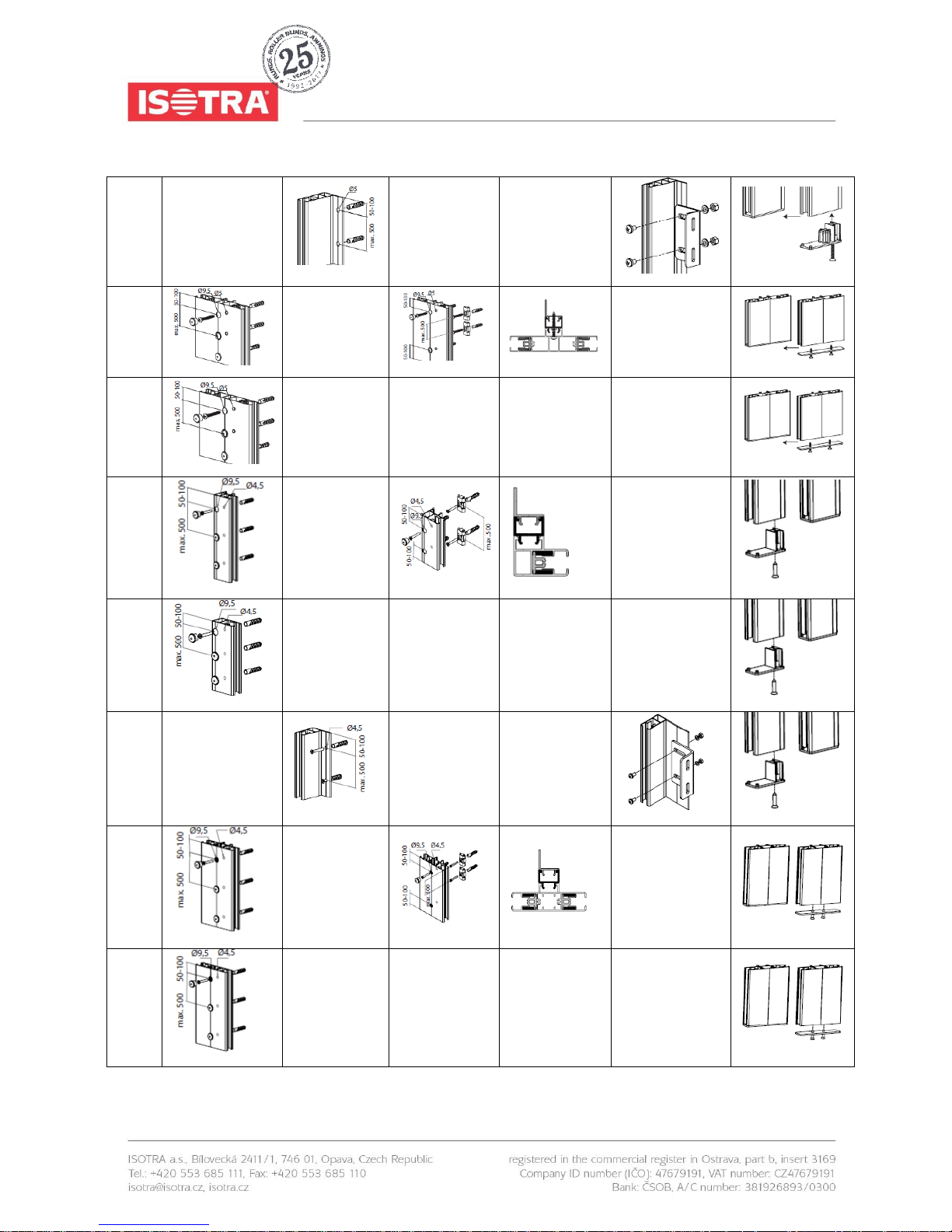
828
855
856
839
830
838
865
866

MEASUREMENT AND ASSEMBLY MANUAL
Validity of the manual: 1. 6. 2017
6
* Clip mounting
These guide rails have two small L-shaped notches on the back. These are either used for clipping the guide rails to the
window frame, using the provided clips, or they are fitted with sealing strips.
The clips must be screwed on each side of the window frame in one straight and vertical line.
** Sealing strips
When the screen is mounted to a window frame on which the surfaces for the two guide rails are not flush, the resulting
gaps between the guide rails and the window frame can be sealed with sealing profiles.
These sealing profiles must always be secured by a screw at the top and the bottom of the guide rail. Be careful when
tightening the fasteners, because overtightening can permanently damage the sealing profiles.
In the interest of safety, it is important that each guide rail be additionally secured to the window frame at the top,
middle and bottom with a sheet metal screw to prevent the guide rail from sliding and the clips from detaching
from the screen.
*** Distance supports
For guide rails with a mounting flange (type 828), distance supports can be used for mounting the guide rails.
**** Cover cap
For each of the guide rails of the type referred to above, use a cover cap at the bottom end. This will prevent the bottom
slat from dropping out of the guide rails.
U-shaped guide profile:
A plastic screen guide profile fits into the U-channel of each guide rail, which accommodates the zipper on the fabric.
(At the top end of this extrusion, the black rubber part is cut away at an angle over a length of 70 mm.
Make sure the guides are positioned with these cut-aways at the top. The screen guide profiles for the left and right sides
differ.)
2.5. PIN MOUNTING
In this installation the box is mounted onto the guide rails by sliding the pivots on each of the side consoles into the
corresponding hole chambers on the guide rails.
To make some of the following steps easier, it is recommended that you unroll the screen a bit so the bottom slat extends
a few centimetres from the box. To do so, use a test cable to briefly operate the motor or operate the manual gearbox with
a crank handle attached to a square rod inserted through the opening in the box.
Based on the installation situation, there are several ways the screen can be installed:
Method 1. Affix the box using the mounting brackets, then slide the guide rails onto the console pivot and secure the guide
rails with screws.
Method 2. Place the complete box / guide rail assembly in or against the window opening and screw them in place.
Mehtod 3. Screw the guide rails in place. Then push the box onto the guide rails and secure it in place.
MEASUREMENT AND ASSEMBLY MANUAL
Validity of the manual: 1. 6. 2017
7
2.5.1. METHOD 1 – AFFIX THE BOX USING THE MOUNTING BRACKETS, THEN SLIDE
THE GUIDE RAILS ONTO THE CONSOLE PIVOT AND SECURE THE GUIDE RAILS
WITH SCREWS
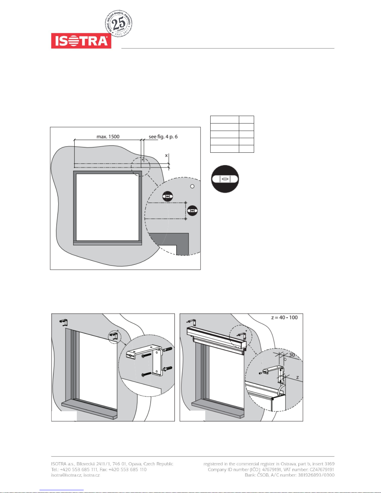
Step 1: Drilling holes for the mounting brackets
Box type
X
70
37
90
53
110
73
150
114
spirit level
Place the mounting brackets against the
mounting surface. Use the upper holes for
mounting against a ceiling and the rear
holes for mounting against a wall.
The box must be perfectly level, so make
sure the brackets are aligned properly. Use
a hose level and a plumb line or another
suitable tool for this task.
fig. 4
fig. 5
fig. 6
 Loading...