

Page 1
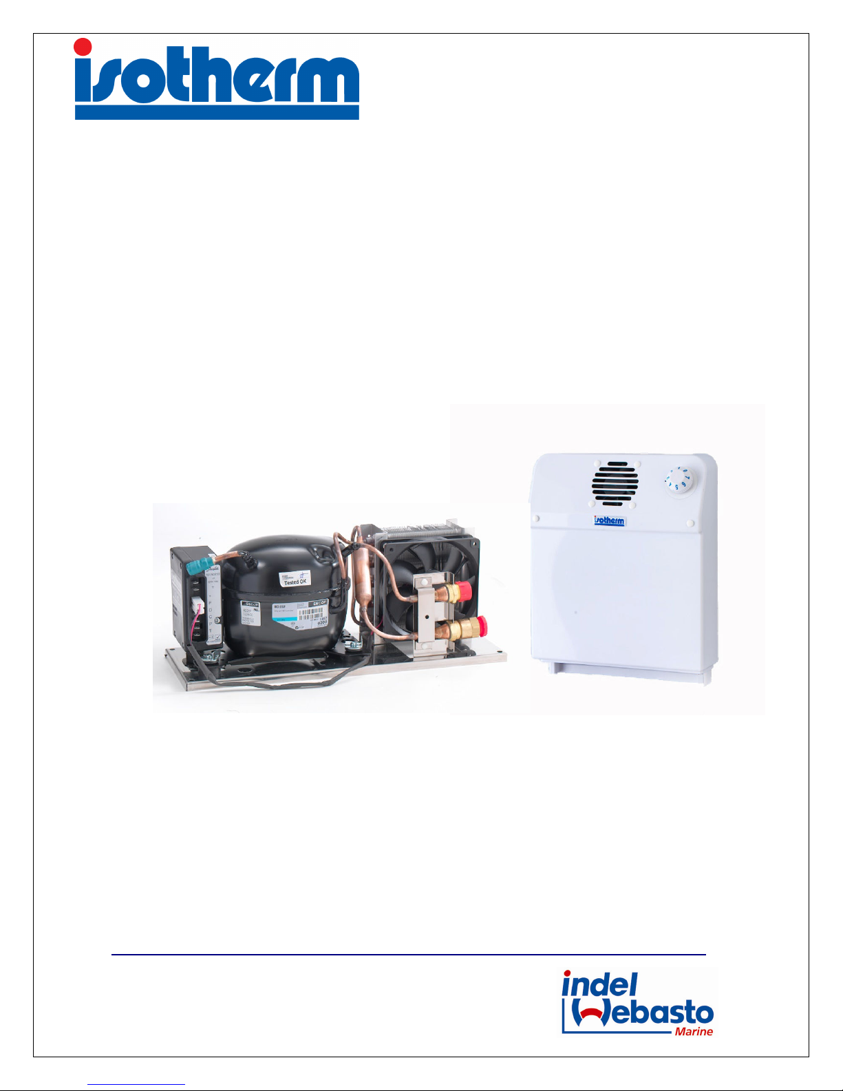
Manuale Istruzioni Unità Refrigerante VE150
VE150 Cooling Unit Instruction Manual
Manuel d’Instructions Unité Réfrigérante VE150
Bedienungsanleitung Kühleinheit VE150
47866 – Sant’Agata Feltria (RN) – ITALY
Tel. +39 0541 848030 Fax +39 0541 848563
info@indelwebastomarine.com
www.indelwebastomarine.com
Zona Artigianale snc
Page 2

VE150 Cooling Unit
Prima di effettuare la messa in funzione leggere accuratamente questo manuale di istruzioni,
conservarlo e in caso di rivendita dell’apparecchio consegnarlo al cliente successivo.
AVVERTENZE
- La mancata osservanza delle indicazioni può causare danni a persone e apparecchi
- Non è ammesso l’impiego di questa apparecchiatura per altri fini rispetto a quelli descritti in
questo manuale.
SICUREZZA GENERALE
- Far installare l’apparecchiatura solo da personale qualificato.
- Se l’apparecchiatura presenta danni visibili, evitare di metterla in funzione.
- L’apparecchiatura deve essere riparata solo da personale specializzato (centri Assistenza Indel
Webasto Marine), le riparazioni effettuate in modo non adeguato potrebbero causare danni a
cose o persone.
- Non aprire in nessun caso il circuito di raffreddamento.
- Installare l’apparecchio in un posto asciutto, protetto da eventuali spruzzi d’acqua e riparato dai
raggi solari diretti.
- Non collocare l’apparecchio nelle vicinanze di fiamme libere o altre fonti di calore
(riscaldamento, raggi solari diretti, forni a gas, etc.).
- Assicurarsi che l’unità refrigerante (compressore) sia sufficientemente ventilata.
- L’apparecchio deve essere conservato e/o installato lontano dalla portata dei bambini.
- Prima della messa in funzione dell’apparecchio, verificare se la tensione di esercizio e quella della
batteria corrispondono.
- Per il collegamento all’alimentazione elettrica principale utilizzare sistemi di protezione e/o
interruttore differenziale (∆I 0,03 A).
- Se il cavo di allacciamento risulta essere danneggiato è necessario sostituirlo con un cavo dalle
stesse specifiche tecniche (sezione e lunghezza).
- Per la pulizia generale dell’apparecchiatura non utilizzare mai detergenti contenenti sostanze
sabbiose, acide o solventi.
- Proteggere l’apparecchiatura da pioggia ed umidità.
- Prima di collegare il carica batterie rapido, disconnettere l’alimentazione principale
dell’apparecchiatura.
- Non toccare mai a mani nude eventuali cavi scoperti e/o danneggiati.
- Disconnettere l’apparecchiatura dalla rete di alimentazione se non utilizzata per lunghi periodi.
- Le batterie possono contenere liquidi acidi aggressivi e corrosivi, evitare che gli stessi vengano a
contatto con occhi/pelle.
2
Page 3
VE150 Cooling Unit
INSTALLAZIONE ED USO
L’apparecchio refrigerante Isotherm VE150 è progettato specificatamente per l’installazione all’intero di
un box appositamente realizzato per la refrigerazione e conservazione degli alimenti, oppure può essere
impiegato per refrigerare un vano già esistente non utilizzato.
L’apparecchio è dotato di tutti componenti necessari per il suo montaggio, facilmente eseguibile senza
l’utilizzo di attrezzature particolari.
In fase di produzione viene caricato con il gas refrigerante idoneo e fornito pronto per l’utilizzo.
Per semplificare l’installazione, il sistema è diviso in 2 sezioni: gruppo condensatore e gruppo
evaporatore.
Queste sezioni sono collegate assieme mediante un tubo flessibile munito di attacchi rapidi che possono
essere facilmente collegati e scollegati ripetutamente senza alcuna perdita di refrigerante.
Quando una delle due parti (gruppo condensatore o gruppo evaporatore) deve essere sostituita o
modificata, è necessario ripetere la procedura vuoto/ricarica del gas.
Il box di alloggiamento dell’evaporatore, deve essere ben isolato. Usare una schiuma poliuretanica o
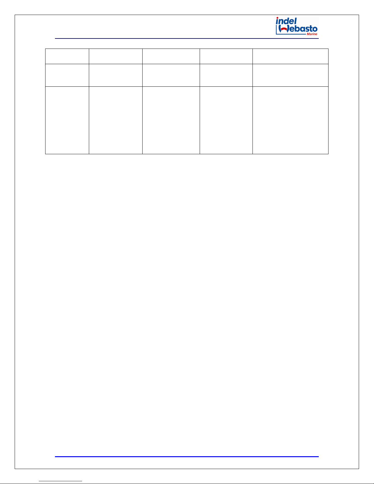
pannelli isolanti dalle seguenti sezioni consigliate:
Volume Box (lt) Spessore Materiale Isolante
L ≤ 100 30 mm
100 < L ≤ 150 50 mm
150 < L ≤ 200 80 mm
200 < L ≤ 250 100 mm
La capacità della batteria deve essere di almeno 75Ah per consentire un corretto funzionamento
dell’unità.
Tutti i dispositivi di alimentazione elettrica devono essere mantenuti sempre in buone condizioni.
Nota: La capacità raffreddante dell’unità è determinata dalla resistenza collegata tra il morsetto “T” della
centralina e un polo del termostato. Per volumi superiori ai 150 litri o per box/vani realizzati con materiale
a basso potere isolante termico, la resistenza deve essere presente. Per volumi inferiori ai 150 litri la
resistenza deve essere omessa. Vedi schema elettrico.
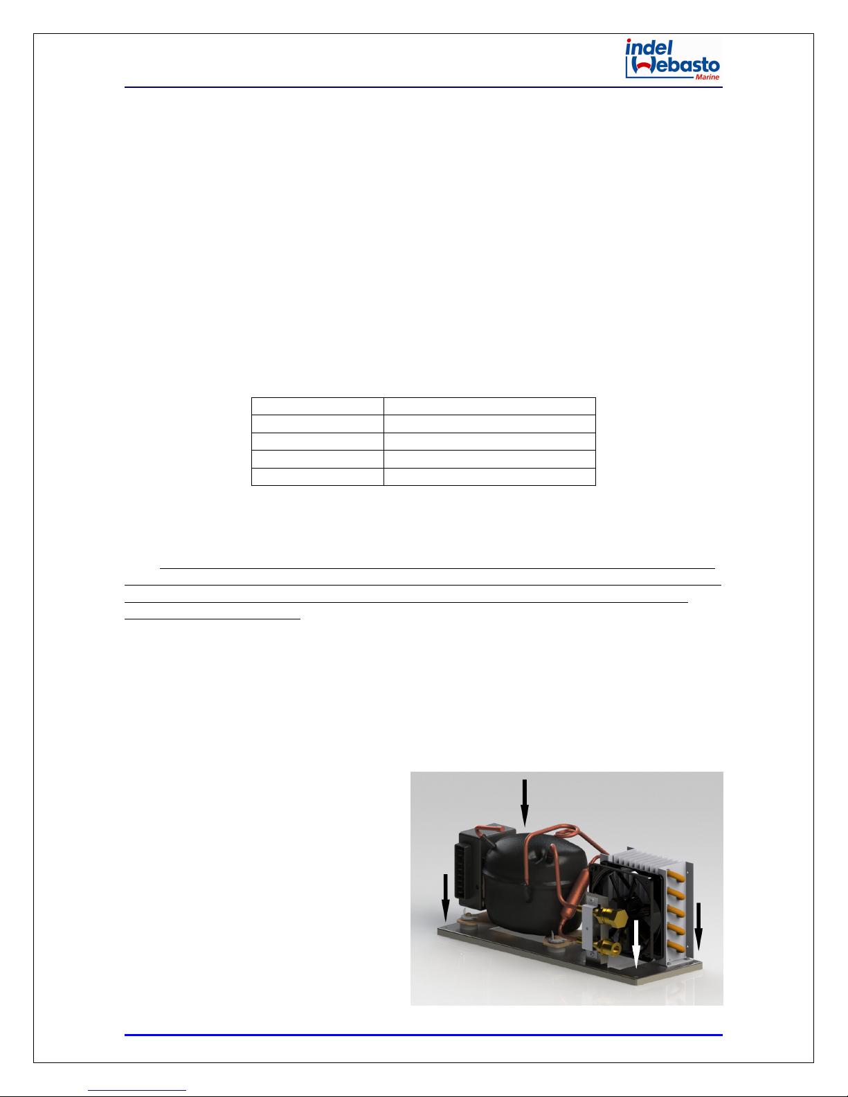
INSTALLAZIONE DEL GRUPPO CONDENSATORE
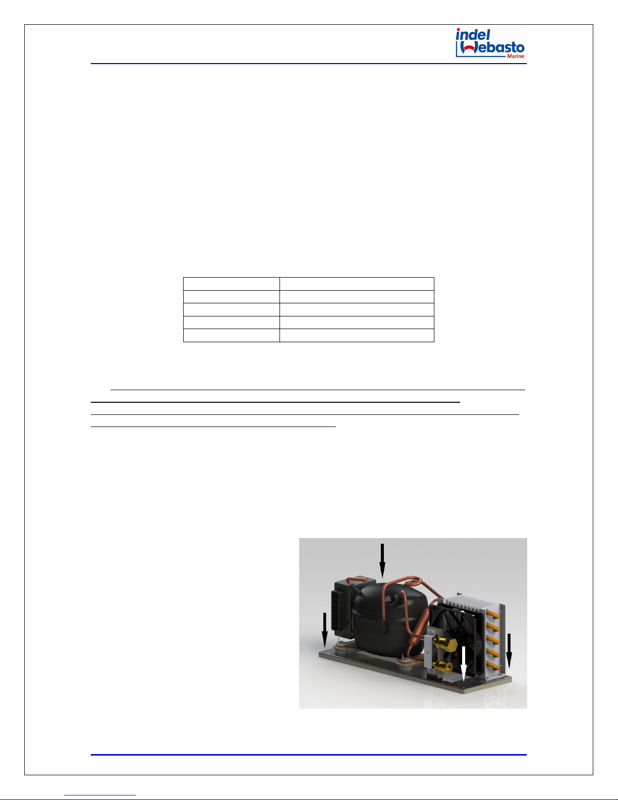
Il gruppo condensatore deve essere installato in posizione orizzontale, può funzionare costantemente fino
ad una inclinazione massima di 30°. Deve essere installato in un ambiente ben ventilato e riparato da
eventuali spruzzi d’acqua, se l’apparecchio viene installato in uno spazio ristretto l’areazione deve essere
migliorata mediante fori di ventilazione del diametro di 8 cm, uno situato sulla parte superiore ed uno
sulla parte inferiore della zona di installazione. Il
gruppo deve essere fissato attraverso i quattro
fori situati sulla basa del supporto del gruppo
condensatore.
Vedi figura a lato.
Posizionare il gruppo condensatore vicino alla
postazione nella quale si prevede di installare il
gruppo evaporante, in modo da non superare la
lunghezza del tubo di collegamento (2mt circa).
3
Page 4
VE150 Cooling Unit
CONNESSIONI ELETTRICHE
L’unità elettronica deve essere collegata direttamente alla batteria o all’interruttore principale, protetta
da sintemi di sicurezza: fusibile, interruttori automatici o interruttori differenziali nel caso di
alimentazione alternata. Il fusibile per la connessione elettrica in corrente continua deve essere almeno di
15A per tensione 12Vdc e almeno 7,5A per tensione 24Vdc.
E’ molto importante utilizzare i cavi di sezione corretta per l’alimentazione principale.
La sezione dei cavi minima, in proporzione alla distanza tra l’unità e la batteria, e indicata in tabella:
Sezioni Cavo mm² Lunghezza Max (mt) 12Vdc Lunghezza Max (mt) 24Vdc
2,5 0 – 2,5 0 – 5
4 2,5 – 4 5 – 8
6 4 – 6 8 – 12
Per evitare perdite di tensione e potenza, il cavo deve essere il più corto possibile e non essere interrotto.
L’unità elettrica include una protezione elettronica contro l’inversione di polarità. Per proteggere la
batteria l’unità si spegne automaticamente quando la tensione non’è più sufficiente.
12 Vdc 24Vdc
Cut-Out Cut-In Max Cut-Out Cut-In Max
9,6V 10,9V 17V 21,3V 22,7V 31,5V
Se l’unità refrigerante è alimentata con un collegamento alla terra con una rete a corrente alternata (100240 Vac) è necessario inserire un interruttore differenziale di protezione tra la rete elettrica e l’unità
refrigerante (∆I 0,03 A).
4
Page 5
VE150 Cooling Unit
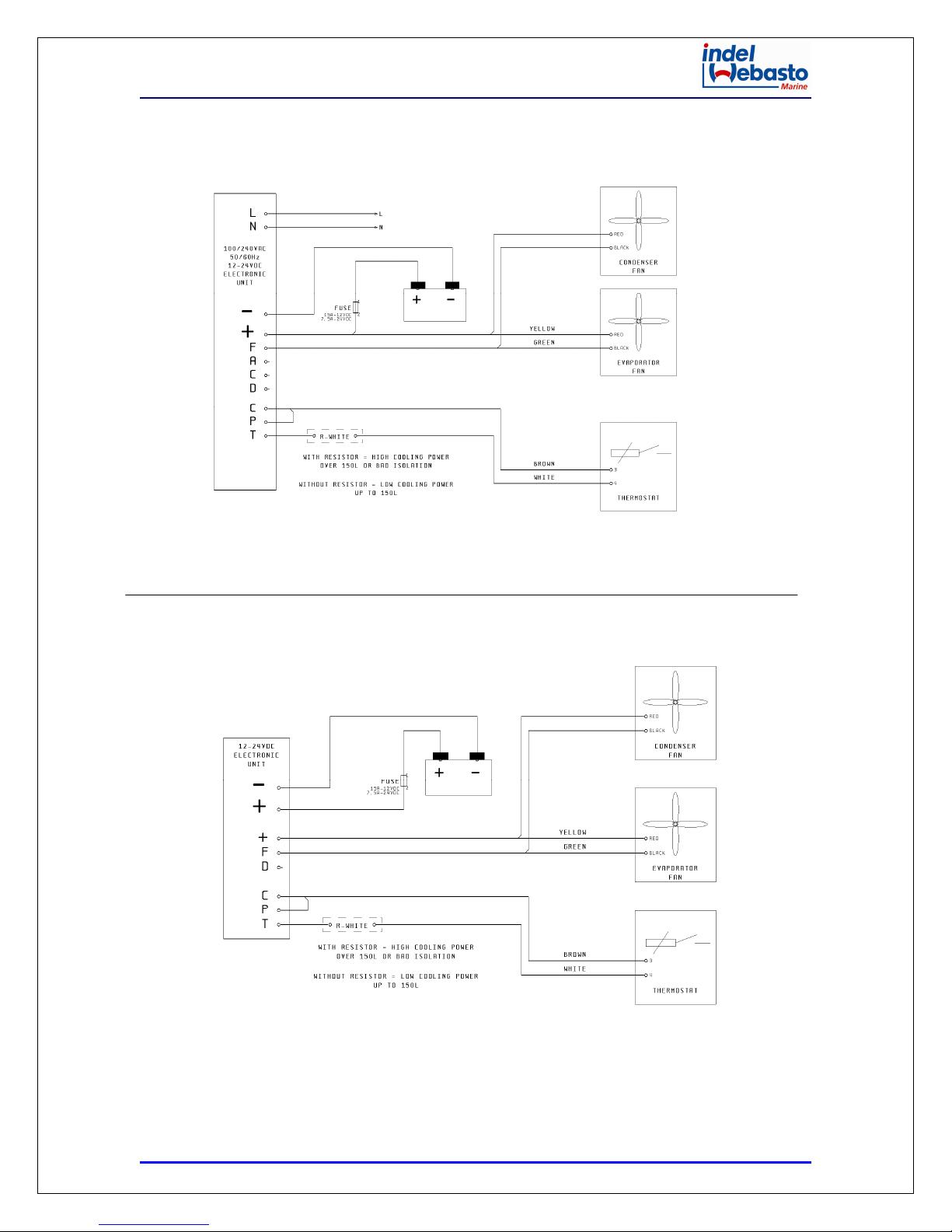
SCHEMA ELETTRICO
AC
DC
5
Page 6
VE150 Cooling Unit
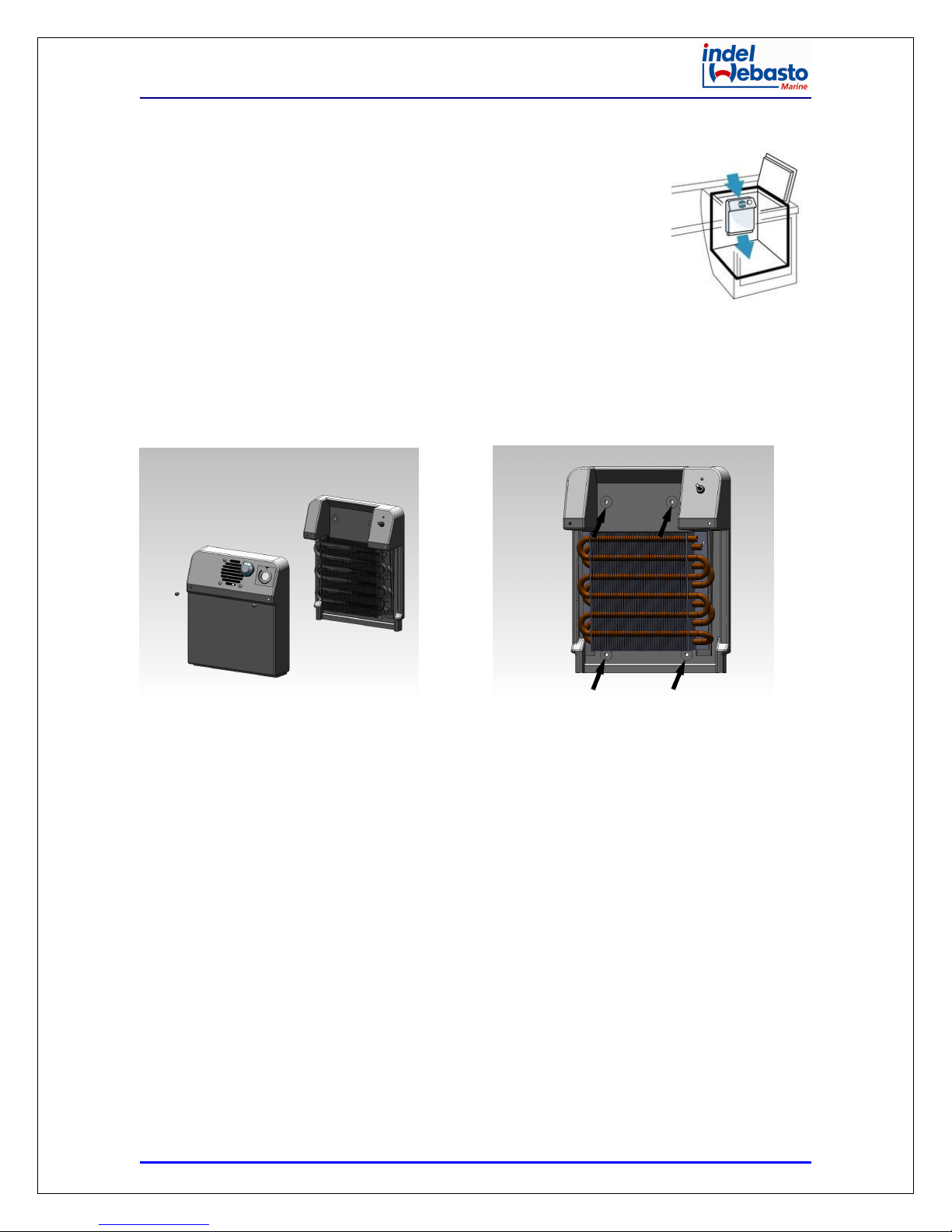
INSTALLAZIONE DEL GRUPPO EVAPORANTE
L’evaporatore deve essere posizionato nella parte più alta all’interno del
box/vano in posizione verticale. Vedi figura a lato.
Praticare un foro del diametro di 30mm nella parete del box/vano per il
passaggio del tubo flessibile con gli attacchi rapidi.
Prima di installare il gruppo evaporante, svolgere completamente il tubo
mantenendo sempre le coperture di protezione sugli attacchi rapidi finché non si
effettuerà il collegamento con la parte condensatrice.
Partendo dall’interno del box/vano, far passare il tubo con gli attacchi rapidi
attraverso il foro precedentemente effettuato fino a raggiungere il gruppo condensatore facendo
attenzione a non piegare a schiacciare il tubo. Il tubo non può essere accorciato perché carico di gas
refrigerante. Il tubo in eccesso può essere avvolto a spirale con un raggio di curvatura minimo di 10cm e
deve essere fissato per impedire la generazione di vibrazioni e rumorosità.
Fissare il gruppo evaporante attraverso gli appositi fori predisposti e sigillare l’apertura creata per il
passaggio del tubo con sigillante o schiuma.
COLLEGAMENTO MECCANICO/ELETTRICO
Gli attacchi rapidi possono essere a questo punto connessi come segue:
collegare prima il giunto rapido con il tubo capillare e successivamente quello con il tubo di aspirazione
ruotando solo il dado dell’attacco femmina, avvitando gli attacchi fino a battuta della filettatura quindi
stringerli saldamente utilizzando utensili idonei per 1/6 di giro o 60° di rotazione massima.
Non gettare le coperture di protezione dei giunti rapidi se fosse necessario riposizionare
l’apparecchiatura, in tal caso gli attacchi possono essere riaperti senza che fuoriesca il gas refrigerante e
immediatamente devono essere protetti dai loro tappi protettivi.
Successivamente collegare le connessioni elettriche come da schema elettrico. Vedi schema elettrico.
6
Page 7

VE150 Cooling Unit
AVVIAMENTO
Effettuare una prova di funzionamento dell’apparecchiatura ruotando in senso orario la manopola del
termostato. Il compressore deve avviarsi entro pochi secondi. Controllare che la ventola di
raffreddamento del condensatore e quella di distribuzione del gruppo evaporante siano in funzione. Dopo
qualche minuto dall’avvio, il gruppo evaporante inizierà a raffreddarsi producendo aria fredda dalla parte
inferiore.
La temperatura è regolabile tramite l’apposita manopola di regolazione, con una scala valori che va da 0 a
7, dove 7 è il valore di massima produzione di freddo e 0 è il valore di stop/spegnimento.
MANUTENZIONE
L’apparecchio refrigerante completo può rimanere sull’imbarcazione durante l’inverno, per mantenere
l’efficienza rimuovere periodicamente la polvere che può essersi accumulata sul condensatore.
NOTE GENERALI
L’unità refrigerante è costruita per refrigerare box/vani atti alla conservazione di alimenti, un uso
improprio e diverso è da considerarsi pericoloso ed il costruttore declina ogni responsabilità per eventuali
danni.
Imballaggio: Lo smaltimento dell’imballaggio e dell’unità deve essere effettuato in accordo con le leggi
ambientali vigenti nel luogo di utilizzo. Assicurarsi che il prodotto sai smaltito correttamente.
Gli alimenti inseriti nel Box/Vano refrigerato dovranno essere mantenuti in contenitori adatti agli alimenti
o nella confezione originale.
7
Page 8
VE150 Cooling Unit
Trouble Shooting
Problema Motivo Possibile
Soluzione/Controllo
Unità Ventilata
L’Unità
refrigerante
non parte –
Unità nuova
La tensione
dell’alimentazione
principale è
troppo bassa
Unità elettronica
difettosa ( caso
raro)
L’unità lavora per
un tempo limitato
L’unità non’è
connessa o sono
invertite le polarità
Controllare la
sezione dei cavi tra
la batteria e la
scheda elettronica
Controllare la
corretta tensione
sulle connessioni
dell’unità
elettronica, la
tensioned eve
essere tra 10,5V e
13,5V per batteria
12V e tra 21V e 27V
per batteria 25V.
I cavi sono ossidati Sostituire i cavi
Il termostato non’è
connesso
Il termostato è
rotto!
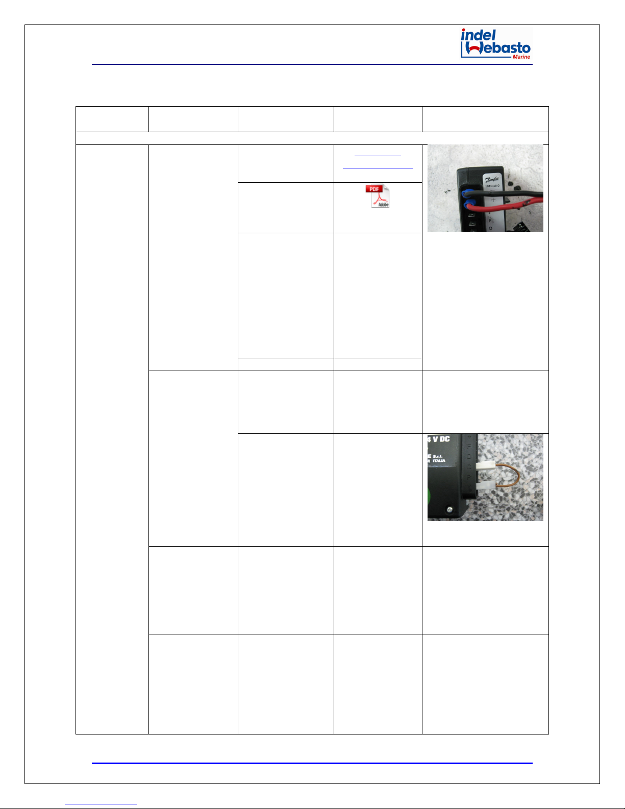
Eseguire un ponte
tra C e T sull’unità
elettronica e
controllare se il
compressore si
avvia
Esguire un ponte tra
le connessioni C e T
sull’unità
elettronica. L’unità
non si avvia fino a
che il voltaggio è
corretto.
Il condensatore non
ha la sufficiente
ventilazione
Soluzione Note
Controllare
connessione cavi
101N0210.pdf
Ricaricare la
batteria – se la
batteria è più
vecchia di 3/4
anni potrebbe
essere necessario
sostituirla!
Controllare la
connessione del
termostato e
dell’unità
elettronica
Sostituire il
termostato
Sostituire l’unità
elettronica
Rimuovere l’unità
dalla sua
postazione e
riavviarla, se
l’unità lavora
correttamente
aumentare la
ventilazione
Termostato
8
Page 9
VE150 Cooling Unit
Problema Motivo Possibile
Soluzione/Controllo
L’unità lavora
per qualche
secondo –
unità nuova
L’unità lavora
ma non
raffredda –
Unità nuova
meno di 0,5 sec.
L’unità lavora fino
a 2 sec.
L’unità lavora da 3
a 5 sec.
Poco gas presente
nel sistema
Troppo gas caricato Rimuovere il gas
L’unità è bloccata
tra il compressore
ed il condensatore
Guaradare la
sezione "L'unità
lavora per qualche
secondo - Unità
nuova"
Ventola difettosa –
scollegare i cavi
della ventola e
controllare se
l’unità lavora
Controllare se i
connettori rapidi
sono lenti o troppo
stretti
Perdita di gas
1. Il consumo
è < del normale.
Soluzione Note
in eccesso
dall’unità. La
pressione del gas
potrebbe
dipendere dalla
temperature. In
circostanze
normali la
pressione interna
potrebbe
raggiungere i 3,5
bar con
temperature
comprese tra i
20°-25°C.
Attenzione
situazione
pericolosa, il
problema può
essere risolto da
un Tecnico
specializzato. Non
c’è pericolo per le
persone ed il
sistema.
Sostituire la
ventola
Se i connettori
sono lenti,
avvitarli a mano
fino che è possible
dunque utilizzare
un utensile per
continuare fino ad
un quarto di giro
(Massimo). Se
sono troppo
stretti, sostituirli.
Chiudere la
perdita tramite
saldatura quando
Informazioni dettagliate
posso essere richieste se
Mettere il Sistema sotto
pressione con max. 5bar di
Azoto, ricercare la perdita
L’unità lavora per
necessario.
9
Page 10
VE150 Cooling Unit
Problema Motivo Possibile
Soluzione/Controllo
2. La
pressione sulla
valvola di carica è <
0 quando il sistema
lavora.
3. La
pressione sulla
valvola di carica è <
1,5 bar quando il
Sistema è spento
Presenza di
umidità
all’interno del
capillare
dell’avaporatore
Presenza di
umidità
all’interno del
cabinet
1. Il consumo
è < 20% del normale
2. La
pressione sulla
valvola di carica è <
di 0 quando il
Sistema è in
funzione
3. La
pressione sulla
valvola di carica è <
1,5 quando il
Sistema è spento
L’umidità all’interno
del bauletto può
passare attraverso
la guarnizione o I
fori dei tubi presenti
nel bauletto –
presenza di ghiaccio
attorno
all’evaporatore
Soluzione Note
possibile o
rimuovere le parti
forate.
Spegnere il
Sistema, aspettare
5 min., quando il
capillare si è
riscaldato
riaccendere il
sistema,
controllare se si
ripresenta lo
stesso problema.
Se la pressione si
mantiene sotto lo
0, riscaldare il
capillare quando il
sistema è acceso.
Se la pressione si
mantiene sotto lo
0 è necessario
inviare l’unità in
laboratorio.
Guardare dove il
ghiaccio è più
spesso,
normalmente
l’umidità si
presenta in
questo punto
Riposizionare la
guarnizione
modellandola
manualmente, se
non’è possible
utilizzare una
moderata
sorgente di
riscaldamento.
Sostituire la
guarnizione dove
con il cercafughe.
Maggiori informazioni
posso essere richieste se
necessario
10
Page 11

VE150 Cooling Unit
Problema Motivo Possibile
Soluzione/Controllo
L’unità non si
avvia – Unità
funzionava
correttamente
L'unità lavora
per qualche
secondo -
Unità
funzionava
correttamente
L’unita lavora
ma non
raffredda –
Unità nuova
L’unità
funziona in
continuazione
Il termostato
Troppo gas
caricato nel
sistema
L’alimentazione
generale è troppo
bassa
Termostato Termostato
Unità elettronica
difettosa
Tutto è installato
correttamente,
carica gas
corretta, il
sistema non
raffredda
correttamente
(caso rao)
Il cabinet è troppo
grande
non’è installato
sull’evaporatore o
installato in
Basse prestazioni –
consumo
leggermente più
alto e presenza di
ghiaccio su I tubi tra
l’evaporato ed il
compressore
Connessione
elettrica
Controllare la
tensione
I cavi sono ossidati
difettoso!
Il consumo elettrico
è leggermente
incrementato e la
pressione
all’interno del
Sistema è corretta
Controllare le
dimensioni del
cabinet e la capacità
massima di
raffreddamento
dell’unità. L’unità
installata è quella
corretta?
Controllare se il
sensore del
termostato è
installato
Soluzione Note
possibile o la
porta
Rimuovere poco
gas alla volta
attraverso la
valvola di carica e
controllare la
pressione
all’interno del
sistema
Controllare
connessione
elettrica
Sostituire il
compressore
Avete l’unità
errata per il
Vostro bisogno!!!
Posizionare il
sensore nella
corretta sede
11
Page 12
VE150 Cooling Unit
Problema Motivo Possibile
Soluzione/Controllo
posizione errata sull’evaporatore o
in una posizione
non corretta
Umidità presente
all’interno del
cabinet
L’umidità può
penetrare
all’interno del
cabinet attraverso
la guarnizione o I
fori per il passaggio
dei tubi. Ghiaccio
presente attorno
all’evaporatore
Soluzione Note
Cercare dove
l’umidità penetra
attraverso del
cabinet
12
Page 13

VE150 Cooling Unit
SICUREZZA
Non utilizzare l’apparecchiatura in caso di danni visibili, sia meccanici che elettrici.
Non aprire mai il circuito refrigerante, tranne i giunti ad accoppiamento rapido se sono del tipo autosigillante e concepiti a tale fine.
Verificare che la ventilazione del compressore non sia bloccata. Se è presente un carica batterie, questo
deve essere connesso alla batteria e mai direttamente all’unità refrigerante.
SPECIFICHE TECNICHE
Alimentazione DC: 12/24Vdc
Assorbimento DC: 6/3 A
Alimentazione AC: 100/240Vac
Assorbimento AC: 0,7 A
Consumo Energetico Medio: 500Watt/24h
Compressore: BD35F
Refrigerante: R134a
Capacità Refrigerante: Fino a 250 Litri
Fusibili DC: 15A-12Vdc / 7,5A-24Vdc
Int. Aut. Diff: 6A Vac (∆I 0,03 A)
13
Page 14
VE150 Cooling Unit
Before starting up the unit, read this instruction manual carefully, store it and pass it on the next
customer if the unit is resold.
WARNINGS
- Failure to follow instructions may cause damage and/or injury
- This unit may not be used for purposes other than those described in this manual.
GENERAL SAFETY
- The unit must only be installed by qualified personnel.
- If the unit shows visible signs of damage, do not operate it.
- The unit must only be repaired by specialised personnel (Indel Webasto Marine Service Centres).
Repairs performed inadequately could cause damage and/or injury.
- Under no circumstances open the cooling circuit.
- Install the unit in a dry place, protected from any splashes of water and direct sunlight.
- Do not place the unit near naked flames or other heat sources (heating, direct sunlight, gas ovens
etc.).
- Ensure that the cooling unit (compressor) is sufficiently ventilated.
- The unit must be stored and/or installed out of reach of children.
- Before operating the unit, ensure that the operating voltage and the battery voltage match.
- In order to connect to the main electricity supply, use protection systems and/or a circuit breaker
(∆I 0.03 A).
- If the connecting cable is damaged, it must be replaced with a cable that has the same technical
specifications (cross-section and length).
- For general cleaning of the unit, never use detergents containing sandy substances, acids or
solvents.
- Protect the unit from rain and moisture.
- Before connecting the quick charger, disconnect the main power supply to the unit.
- Never touch any exposed and/or damaged wires with bare hands.
- Disconnect the unit from the mains when not in use for long periods.
- The batteries may contain aggressive acidic and corrosive liquids. Ensure these do not come into
contact with eyes/skin.
14
Page 15
VE150 Cooling Unit
INSTALLATION AND USE
The Isotherm VE150 cooling unit is specifically designed to be installed inside a box that has been specially
made for chilling and storing food, or can be used to chill a compartment that already exists but is not in
use.
The unit is equipped with all the components necessary for its assembly, which is easy and does not
require specific tools.
During the production stage, it is loaded with the appropriate refrigerant and delivered ready for use.
To simplify installation, the system is divided into 2 sections: the condenser unit and the evaporator unit.
These sections are connected together via a hose equipped with quick couplings that can be easily
connected and disconnected repeatedly without any loss of refrigerant.
When one of the two parts (condenser unit or evaporator unit) must be replaced or modified, the gas
emptying/recharging procedure must be repeated.
The box housing the evaporator must be well insulated. Use a polyurethane foam or insulation panels
with the following recommended cross-sections:
Box Volume (l) Thickness of Insulation Material
L ≤ 100 30 mm
100 < L ≤ 150 50 mm
150 < L ≤ 200 80 mm
200 < L ≤ 250 100 mm
The battery capacity must be at least 75 Ah to enable correct unit operation.
All electrical power supply devices must always be kept in good condition.
N.B. The cooling capacity of the unit is determined by the resistor connected between the terminal “T” on
the control unit and one pole of the thermostat. For volumes greater than 150 litres or for
boxes/compartments made using material with low thermal insulation, the resistor must be present. For
volumes less than 150 litres, the resistor should be omitted. See the wiring diagram.
INSTALLING THE CONDENSER UNIT
The condenser unit must be installed horizontally, and can operate constantly at a maximum gradient of
30°. It must be installed in a well-ventilated environment, protected from splashes of water. If the unit is
installed in a confined space, ventilation should be improved by creating ventilation holes with a diameter
of 8 cm, one located on the top and one on the bottom of the installation area. The unit must be secured
through the four holes situated on the
condenser unit support base.
See the figure on the right.
Place the condenser unit near the location
where you plan to install the evaporator unit, so
as not to exceed the length of the connecting
hose (about 2 m).
15
Page 16

VE150 Cooling Unit
ELECTRICAL CONNECTIONS
The electronic unit must be connected directly to the battery or the main switch, protected by safety
systems: fuses, automatic switches or circuit breakers in the case of AC power. The fuse for the direct
current electrical connection must be at least 15 A for 12 VDC and at least 7.5 A for 24 VDC.
It is very important to use cables with the right cross-section for the main power supply.
The minimum cross-section of the cables, in proportion to the distance between the unit and battery, is
shown in the table:
Cable cross-section
(mm²)
2.5 0 – 2.5 0 – 5
4 2.5 – 4 5 – 8
6 4 – 6 8 – 12
To avoid loss of voltage and power, the cable must be as short as possible and not be interrupted.
The electrical unit includes electronic protection against polarity reversal. To protect the battery, the unit
shuts off automatically when the voltage is no longer sufficient.
Cut-Out Cut-In Max Cut-Out Cut-In Max
9.6 V 10.9 V 17 V 21.3 V 22.7 V 31.5 V
If the cooling unit is supplied with a connection to earth with an AC network (100-240 VAC), it is necessary
to insert a protective circuit breaker between the electrical mains and the cooling unit (∆I 0.03 A).
Max length (m) 12 VDC Max length (m) 24 VDC
12 VDC 24 VDC
16
Page 17

VE150 Cooling Unit
WIRING DIAGRAM
AC
DC
17
Page 18

VE150 Cooling Unit
INSTALLING THE EVAPORATOR UNIT
The evaporator must be placed at the top inside the box/compartment in an
upright position. See the figure on the right.
Drill a hole with a 30 mm diameter in the wall of the box/compartment so that
the hose with the quick couplings can pass through.
Before installing the evaporator unit, fully extend the hose, keeping the
protective covers on the quick couplings until connection is made with the
condenser part.
Starting from inside the box/compartment, pass the hose with the quick
couplings through the hole drilled beforehand, until reaching the condenser unit, being careful not to
bend or crush the hose. The hose cannot be shortened as it is full of refrigerant. The excess hose can be
coiled with a minimum bend radius of 10 cm and must be secured to prevent vibration and noise being
generated.
Secure the evaporator unit through the appropriate holes and seal the opening created by the passage of
the hose with sealant or foam.
MECHANICAL/ELECTRICAL CONNECTION
The quick couplings can be connected at this point as follows:
first connect the quick joint to the capillary hose and then the latter to the suction hose, turning the
female coupling unit only, tightening the couplings until reaching the end of the threads then securing
them tightly using suitable tools for 1/6 of a revolution or 60° maximum rotation.
Do not discard the protective covers on the quick joints if it is necessary to reposition the unit, as the
couplings can be reopened without the refrigerant coming out and must be protected immediately using
their protective caps.
Then connect the electrical connections as shown in the wiring diagram. See the wiring diagram.
18
Page 19

VE150 Cooling Unit
START-UP
Test the operation of the unit by turning the thermostat knob in a clockwise direction. The compressor
must start up within a few seconds. Check that the condenser cooling fan and the evaporator unit
distribution fan work correctly. A few minutes after start-up, the evaporator unit will begin to cool down,
producing cold air from the bottom.
The temperature can be adjusted using the control dial, with a scale with values ranging from 0 to 7,
where 7 is the maximum cold production value and 0 is the stop/off value.
MAINTENANCE
The complete cooling unit can remain on the boat during the winter. To ensure it remains efficient,
periodically remove any dust that accumulates on the condenser.
GENERAL NOTES
The cooling unit is built to cool boxes/compartments designed for storing food. Improper use or any other
use is considered dangerous and the manufacturer disclaims any liability for damage or injury.
Packaging: The packaging and the unit must be disposed of in accordance with applicable environmental
laws in the place of use. Ensure that the product is disposed of properly.
The foods inserted in the cooled box/compartment must be kept in containers suitable for use with food
or in the original packaging.
19
Page 20

VE150 Cooling Unit
Troubleshooting
Problems Reasons Possible Issue /
Check
The Cooling
Unit does
not start -
the Unit is
new
The Cooling
Unit works
The main supply
voltage is too
low
Faulty electronic
Unit
(rare case)
Cooling Unit
works for a
short period of
time
It works <0.5
sec.
The unit is not
connect or wrong
polarity
Check the section
of wires between
battery and
electronic unit
Check the
voltage on the
connection right
before the
Electronic Unit,
the voltage must
be between 10.5
V to 13.5 V for
battery at 12 VDC
and 21 to 27 for
battery at 24 VDC
The wires are
oxidized
The thermostat is
not connected
Thermostat is
broken!
Bridge C and T
connections, on
the electronic
unit.
The unit works.
Bridge C and T
connections, on
the electronic
unit.
The unit does not
start even if the
voltage is
correct.
Not enough
ventilation
around the
condenser
Too much gas Remove some gas from
Solution Notes
Air cooled
Check the wire
connection
101N0210.pdf
Recharge the battery -
If the battery is older
than 3 or 4 years it could
be necessary to replace
it!
Replace the wires
Check the correct
connection of the
thermostat on the
electronic unit and on
the thermostat.
Replace the thermostat
Replace the electronic
unit
Remove the fridge from
its place and turn it on, if
it keeps cooling, improve
the ventilation!
the unit. In this situation
Thermostat
20
Page 21

VE150 Cooling Unit
Problems Reasons Possible Issue /
Check
for few
seconds -
the Unit is
new
The unit is
blocked between
compressor and
condenser
The Cooling
Unit works
but it is not
cooling -
The Unit is
new
It works up to 2
sec.
It works from 3
up to 5 sec.
gas in the
system
Presence of
humidity inside
the capillary in
See "The Cooling
Unit works for
few seconds -
the Unit is new"
section
Faulty Fan -
disconnect wire
of fan and check
if the unit works
Check if quick
couplings are
well tightened.
Gas Leakage
4. The
electrical
consumption is
less than normal.
5. The
pressure on
charge valve is
lower than 0 bar
(0 psi) when the
system works
6. The
pressure on
charge valve is
less of 1.5 bar (21
psi) when the
system is off
4. The
electrical
consumption is
Solution Notes
experience is very
important, gas pressure
may vary depending on
temperature. Under
normal circumstances
internal pressure is up to
3.5 bar with
temperature between
20-25°C
Warning, dangerous
situation,
issue can be solved by a
skilled technician.
There is no actual
danger for people or
system.
Replace the fan.
Tight quick couplings as
much as possible by
hand, then use tools to
tight them up to one
quarter of a turn
Where it is possible close
the leak with welding or
remove the part where
is the hole.
Switch off the system,
wait about 5 minutes,
then heat up the
More detailed info can be
requested if needed.
Put the system on pressure
with nitrogen gas max 5
bars (70 psi), search the
leakage with liquid leak
detector or electronic nose
More detailed info can be
requested if needed.
Too low or no
for R134a
21
Page 22

VE150 Cooling Unit
Problems Reasons Possible Issue /
Check
the evaporator. 20% less than
normal.
5. The
pressure on
charge valve is
lower than 0 bar
(0 psi) when the
system works
6. The
pressure on
charge valve is
less of 1.5 bar (21
psi) when the
system is off
The Cooling
Unit does
not start -
the Unit
worked
Presence of
Humidity inside
the cabinet
Too much gas Low performance
The main supply
voltage is too
low
Thermostat Thermostat is
Faulty electronic
Unit
Everything is
well installed,
gas inside the
system, no cool
at all (rare case)
Humidity gets
inside the
cabinet by
passing through
the gasket or
pipes hole
through the
cabinet. /
Ice presence all
over evaporator
- a bit higher
consumption and
presence of ice
on pipe between
evaporator and
compressor.
Electrical
connection
Check the
voltage
The wires are
oxidized
broken!
Power
consumption
greatly increased,
constant
pressure in the
system
Solution Notes
capillary, than turn on
the system, check again
from the beginning. If
pressure keeps going
under 0 bar, heat up the
capillary while the
system is on.
If pressure keeps going
under 0 bar, it is
necessary to bring the
unit back to the
laboratory.
Look where the ice is
thicker, usually humidity
gets in on that side.
Put back in place the
gasket, by modelling it
by hand, if it is not
possible by using
moderate heat source
Replace the gasket
where it is possible or
the door.
Remove gas a bit at a
time, check how
pressure works inside
the system.
Check the wire
connection
Replace the compressor
22
Page 23

VE150 Cooling Unit
Problems Reasons Possible Issue /
Check
The Cooling
Unit works
for few
seconds -
the Unit
worked
The Cooling
Unit works
but it is not
cooling -
The Unit is
new
The Cooling
Unit keeps
working
Thermostat not
installed on the
installed in the
wrong position
Humidity inside
The cabinet is
too big
evaporator or
the cabinet
Check the
cabinet
dimension and
compare it to the
maximum
cooling capacity
of the unit.
Is the correct unit
installed in the
cabinet?
Check if the
probe is installed
on the
evaporator or if it
is in a different
socket
Humidity gets
inside the
cabinet by
passing through
gasket or pipes
hole through the
cabinet.
Ice presence all
over evaporator
Solution Notes
You have wrong cooling
unit!!!
Place the probe in the
appropriate socket
Find where humidity
gets inside from.
23
Page 24

VE150 Cooling Unit
SAFETY
Do not use the unit if there is visible damage, be it mechanical or electrical.
Never open the cooling circuit, except for the quick coupling joints if they are self-sealing and designed for
this purpose.
Check that compressor ventilation is not blocked. If there is a battery charger, it must be connected to the
battery and never directly to the cooling unit.
TECHNICAL DATA
DC power supply: 12/24 VDC
DC absorption: 6/3 A
AC power supply: 100/240 VAC
AC absorption: 0,7 A
Average power consumption: 500 W/24h
Compressor: BD35F
Refrigerant: R134a
Refrigerant capacity: Up to 250 litres
DC fuses: 15 A - 12 VDC / 7.5A - 24 VDC
Circuit breaker: 6A VAC (∆I 0.03 A)
24
Page 25

VE150 Cooling Unit
Avant d’effectuer la mise en fonction lire attentivement ce manuel d’instructions, le conserver et en cas
de revente de l’appareil le remettre au client successif.
AVERTISSEMENTS
- La non-observance des indications peut provoquer des dommages aux personnes et aux
appareils
- L’emploi de cet appareil pour des usages qui sont différents de ceux décrits dans ce manuel est
interdit.
SECURITE GENERALE
- Faire installer l’appareil uniquement par du personnel qualifié.
- Si l’appareil présente des dommages visibles, éviter de le mettre en service.
- L’appareil doit être réparé uniquement par du personnel spécialisé (centres d’Assistance Indel
Webasto Marine), les réparations effectuées de façon non-conforme pourraient causer des
dommages aux personnes et aux appareils.
- Ne jamais ouvrir le circuit de refroidissement.
- Installer l’appareil dans un endroit sec, protégé d’éventuelles projections d’eau et à l’abri des
rayons du soleil directs.
- Ne pas installer l’appareil près de flammes libres ou d’autres sources de chaleur (chauffage,
rayons du soleil, fours à gaz, etc.).
- S’assurer que l’unité réfrigérante (compresseur) est suffisamment ventilée.
- L’appareil doit être conservé et/ou installé loin de la portée des enfants.
- Avant la mise en fonction de l’appareil, vérifier si la tension d’exercice et celle de la batterie
correspondent.
- Pour le branchement à l’alimentation électrique utiliser des systèmes de protection et /ou un
interrupteur à courant différentiel (∆I 0,03 A).
- Si le câble de branchement est endommagé il faut le remplacer par un câble ayant les mêmes
spécifications techniques (section et longueur).
- Pour le nettoyage de l’appareil ne jamais utiliser de détergents contenant des substances
grumeleuses, des acides ou des solvants.
- Protéger l’appareil de la pluie et de l’humidité.
- Avant de brancher le chargeur de batterie rapide, débrancher l’alimentation principale de
l’appareil.
- Ne jamais toucher à mains nues des câbles éventuellement dénudés et/ou endommagés.
- Débrancher l’appareil du réseau d’alimentation lorsqu’on ne l’utilise pas pendant de longues
périodes.
- Les batteries peuvent contenir des liquides acides agressifs et corrosifs, éviter qu’ils n’entrent en
contact avec les yeux, la peau.
25
Page 26

VE150 Cooling Unit
INSTALLATION ET EMPLOI
L’appareil réfrigérant Isotherm VE150 est conçu spécialement pour l’installation à l’intérieur d’un coffre
réalisé spécialement pour la réfrigération et la conservation des aliments, ou pour être utilisé pour
refroidir un compartiment déjà existant non utilisé.
L’appareil est muni de tous les éléments nécessaires à son montage, que l’on peut effectuer facilement
sans l’emploi d’outillage spécial.
En phase de production il est chargé de gaz réfrigérant spécial et fourni prêt à l’emploi.
Pour simplifier l’installation, le système est divisé en 2 sections: groupe condensateur et groupe
évaporateur.
Ces sections sont reliées ensemble grâce à un tuyau flexible muni de raccords rapides qui peuvent être
facilement branchés et débranchés souvent sans aucune fuite de réfrigérant.
Quand une des deux parties (groupe condensateur et groupe évaporateur) doit être changée ou
modifiée, il faut répéter la procédure vide /recharge de gaz.
Le coffre de logement de l’évaporateur, doit être calorifugé. Utiliser une mousse polyuréthane ou des
panneaux isolants ayant les sections conseillées suivantes:
Volume Coffre (lt) Epaisseur Matériel Isolant
L ≤ 100 30 mm
100 < L ≤ 150 50 mm
150 < L ≤ 200 80 mm
200 < L ≤ 250 100 mm
La capacité de la batterie doit être d’au moins 75Ah pour permettre un fonctionnement correct de l’unité.
Tous les dispositifs d’alimentation électrique doivent être toujours conservés en bonnes conditions.
N.B: La capacité réfrigérante de l’unité est déterminée par la résistance branchée entre la borne “T” de la
centrale et un pôle du thermostat. Pour des volumes supérieurs à 150 litres ou pour des
coffres/compartiments réalisés avec des matériaux à capacité d’isolation thermique peu élevée, la
résistance doit être présente. Pour des volumes inférieurs à 150 litres on enlève la résistance. Voir
schéma électrique.
INSTALLATION DU GROUPE CONDENSATEUR
Le groupe condensateur doit être installé en position horizontale, il fonctionne constamment jusqu’à une
inclinaison maximum de 30°. Il doit être installé dans un endroit bien ventilé et à l’abri d’éventuelles
projections d’eau, si l’appareil est installé dans
un espace restreint l’aération doit être
améliorée à l’aide de trous de ventilation d’un
diamètre de 8 cm, un situé sur la partie
supérieure et un sur la partie inférieure de la zone
d’installation. Le groupe doit être fixé par les
quatre trous situés sur la base du support du
groupe condensateur.
Voir figure ci-contre.
Positionner le groupe condensateur près de
l’endroit où on a l’intention d’installer le groupe
évaporateur, de façon à ne pas dépasser la
longueur du tuyau de branchement (environ 2m).
26
Page 27

VE150 Cooling Unit
BRANCHEMENTS ELECTRIQUES
L’unité électronique doit être branchée directement à la batterie ou à l’interrupteur principal, protégée
par des systèmes de sécurité: fusible, interrupteurs automatiques ou différentiels en cas d’alimentation
alternative. Le fusible pour le branchement électrique en courant continu doit être d’au moins 15A pour
une tension de 12Vdc et d’au moins 7,5A pour une tension de 24Vdc.
Il est très important d’utiliser des câbles de section correcte pour l’alimentation principale.
La section minimum des câbles, selon la distance entre l’unité et la batterie, est indiquée dans le tableau
ci-après:
Section câble en mm² Longueur Max (m) 12Vdc Longueur Max (m) 24Vdc
2,5 0 – 2,5 0 – 5
4 2,5 – 4 5 – 8
6 4 – 6 8 – 12
Pour éviter des pertes de tension et de puissance, le câble doit être le plus court possible et sans
interruption.
L’unité électrique comprend une protection électronique contre l’inversion de polarité. Pour protéger la
batterie l’unité s’éteint automatiquement quand la tension n’est plus suffisante.
12 Vdc 24Vdc
Cut-Out Cut-In Max Cut-Out Cut-In Max
9,6V 10,9V 17V 21,3V 22,7V 31,5V
Si l’unité réfrigérante est alimentée avec une prise de terre à un réseau à courant alternatif (100-240 Vac)
il faut insérer un interrupteur à courant différentiel de protection entre le réseau électrique et l’unité
réfrigérante (∆I 0,03 A).
27
Page 28

VE150 Cooling Unit
SCHEMA ELECTRIQUE
AC
DC
28
Page 29

VE150 Cooling Unit
INSTALLATION DU GROUPE EVAPORATEUR
L’évaporateur doit être positionné dans la partie la plus haute à l’intérieur du
coffre/compartiment en position verticale. Voir figure ci-contre.
Pratiquer un trou d’un diamètre de 30 mm dans la paroi du coffre/compartiment
pour le passage du tuyau flexible avec les raccords rapides.
Avant d’installer le groupe évaporateur, dérouler entièrement le tuyau en
maintenant toujours les gaines de protection sur les raccords rapides tant que le
branchement avec la partie condensateur n’est pas effectué.
En partant de l’intérieur du coffre/compartiment, faire passer le tuyau avec les
raccords rapides à travers le trou percé auparavant jusqu’à ce qu’on atteigne le groupe condensateur, en
faisant attention à ne pas plier ou écraser le tuyau. Le tuyau ne doit pas être raccourci car il est plein de
gaz réfrigérant. Le tuyau supplémentaire peut être enroulé en spirale avec un rayon de courbure
minimum de 10 cm et il faut le fixer pour éviter la génération de vibrations et de bruit.
Fixer le groupe évaporateur à l’aide des trous prédisposés et sceller l’ouverture créée pour le passage du
tuyau avec du mastic ou de la mousse.
BRANCHEMENT MECANIQUE/ELECTRIQUE
On peut alors brancher les prises rapides comme indiqué ci-après:
Brancher tout d’abord le raccord rapide au tuyau capillaire et ensuite au tuyau d’aspiration en tournant
seulement l’écrou de la prise femelle, visser les raccords jusqu’à la butée du filetage et serrer solidement
en utilisant des outils adaptés pour 1/6 de tour ou 60° de rotation maximum.
Ne pas jeter les gaines de protection des joints rapides car s’il était nécessaire de positionner l’appareil,
les raccords peuvent être rouverts sans que le gaz réfrigérant ne s’échappe et ils doivent être protégés
immédiatement à l’aide de leurs bouchons de protection.
Ensuite brancher les connexions électriques comme indiqué dans le schéma électrique. Voir schéma
électrique.
29
Page 30

VE150 Cooling Unit
MISE EN MARCHE
Effectuer un essai de fonctionnement de l’appareil en tournant le bouton du thermostat dans le sens des
aiguilles d’une montre. Le compresseur doit démarrer dans les secondes qui suivent. Contrôler que le
ventilateur de refroidissement du condensateur et celui de distribution du groupe évaporateur
fonctionnent. Au bout de quelques minutes du démarrage, le groupe évaporateur commence à refroidir
en produisant de l’air froid dans la partie inférieure.
La température est réglable à l’aide du bouton de réglage, avec une échelle de valeurs qui va de 0 à 7, 7
étant la valeur de production maximum de froid et 0 la valeur d’arrêt/ extinction.
ENTRETIEN
L’appareil réfrigérant complet peut rester sur l'embarcation pendant l'hiver, pour conserver son efficacité
enlever souvent la poussière qui peut s'accumuler sur le condensateur.
NOTES GENERALES
L’unité réfrigérante est construite pour refroidir des coffres/compartiments pour la conservation des
aliments, un emploi impropre et différent doit être considéré comme dangereux et le constructeur
décline toute responsabilité pour d’éventuels dommages.
Emballage: L’élimination de l’emballage et de l’unité doit être effectuée conformément aux lois sur
l’environnement en vigueur dans le lieu d’utilisation. S’assurer que le produit soit éliminé correctement.
Les aliments contenus dans le coffre/compartiment réfrigéré doivent être conservés dans des récipients
pour aliments ou dans leur emballage original.
30
Page 31

VE150 Cooling Unit
Dépannages
Problèmes Causes Emission
possible /
Contrôle
L’Unité de
refroidissement
ne démarre pas
- L’appareil est
neuf
La tension
d’alimentation
principale est
trop basse
Unité
électronique en
panne
(cas rare)
L’appareil n’est
pas connecté ou
a une polarité
erronée
Contrôler la
section des
câbles entre la
batterie et
l’unité
électronique
Contrôler la
tension de la
connexion tout
de suite avant
l’unité
électronique, la
tension doit être
entre 10.5v et
13,5v pour la
batterie de
12vdc et entre
21 et 27 pour la
batterie de
24vdc
Les fils sont
oxydés
Le thermostat
n’est pas
branché
Le Thermostat
est cassé!
Ponter les
connexions C et
T dans l’unité
électronique.
L’unité
fonctionne.
Ponter les
connexions C et
T dans l’unité
électronique
L’appareil ne
fonctionne pas
Refroidi à air
Solution Notes
Contrôler le
branchement des fils
101N0210.pdf
Recharger la batterie
-
Si la batterie a plus
de 3 ou 4 ans il peut
être nécessaire de la
changer!
Changer les fils
Contrôler le
branchement correct
du thermostat sur
l’unité électronique
et sur le thermostat.
Changer le
thermostat
Changer l’unité
électronique
Thermostat
31
Page 32

VE150 Cooling Unit
Problèmes Causes Emission
possible /
Contrôle
même si la
tension est
correcte.
L’Unité de
refroidissement
ne travaille que
pendant
quelques
secondes
L’appareil est
neuf
L’unité de
refroidissement
fonctionne
pendant une
courte période
de temps
<0,5 sec.
Elle fonctionne
2 sec.
Elle fonctionne
de 3 à 5 sec.
Trop peu ou pas
de gaz dans
l’appareil
Ventilation
insuffisante
autour du
condensateur
Trop de gaz Enlever du gaz de
L’appareil est
bloqué entre le
compresseur et
le condensateur
Voir chapitre "
L’Unité de
refroidissement
ne fonctionne
que pendant
quelques
secondes –
L’appareil est
neuf" .
Panne
Débrancher le fil
du ventilateur et
contrôler si
l’appareil
fonctionne
Contrôler si les
couplages
rapides sont
bien serrés.
Solution Notes
Déplacer le frigo et le
mettre en marche, s’il
continue à refroidir,
améliorer la
ventilation!
l’appareil. Dans cette
situation l’expérience
est très importante la
pression du gaz peut
varier selon la
température. En
conditions normales
la pression interne
est de 3,5 bars avec
une température
entre 20-25°C
Attention situation
dangereuse,
Le problème peut
être résolu par un
technicien spécialisé.
Actuellement il n’y a
pas de danger pour
les personnes ou
l’appareil.
Serrer les couplages
rapides à la main
autant que possible,
ensuite utiliser un
Changer le
ventilateur.
Elle fonctionne
Des infos détaillées
peuvent être fournies sur
demande.
32
Page 33

VE150 Cooling Unit
Problèmes Causes Emission
possible /
Contrôle
L’Unité de
refroidissement
fonctionne
mais elle ne
refroidit pas L’appareil est
neuf
Présence
d’humidité dans
le capillaire de
l’évaporateur.
Présence L’humidité Regarder l’endroit où
Fuite Gaz
7. La
consommation
électrique est
inférieure à la
normale.
8. La
pression sur le
robinet de
remplissage est
inférieure à 0
bars (0 psi)
lorsque l’appareil
fonctionne
9. La
pression sur le
robinet de
remplissage est
inférieure à 1,5
bars (21 psi)
lorsque l’appareil
est éteint
10. La
consommation
électrique est
inférieure de
20% à la
normale.
7. La
pression sur le
robinet de
remplissage est
inférieure à 0
bars (0 psi)
lorsque
l’appareil
fonctionne
8. La
pression sur le
robinet de
remplissage est
inférieure à 0
bars 1,5 bars (21
psi) lorsque
l’appareil est
éteint
Solution Notes
outil pour serrer à un
quart de tour
Lorsque c’est
possible colmater la
fuite par une soudure
ou enlever la pièce
qui fuit.
Eteindre l’appareil,
attendre environ 5
minutes, puis
chauffer le capillaire,
faire fonctionner
l’appareil, contrôler
de nouveau depuis le
début. Si la pression
continue à baisser au-
dessous de 0 bars,
chauffer le capillaire
lorsque l’appareil
fonctionne. Si la
pression continue à
baisser au-dessous de
0 bars, il faut faire
appel à l’assistance.
chercher la fuite avec un
électronique pour R134a
peuvent être fournies sur
Mettre l’appareil à une
pression avec de l’azote
max 5 bars (70 psi),
liquide de détection de
fuite ou un nez
Des infos détaillées
demande
33
Page 34

VE150 Cooling Unit
Problèmes Causes Emission
possible /
Contrôle
L’Unité de
refroidissement
ne démarre pas
- L’appareil a
déjà fonctionné
L’Unité de
refroidissement
ne fonctionne
que pendant
d’humidité
dans l’armoire
Trop de gaz Basse
La tension
principale
d’alimentation
est trop basse
Thermostat Le thermostat
L’Unité de
refroidissement
est en panne
Tout est bien
installé, il y a du
gaz dans
l’appareil, mais
pas de
refroidissement
du tout (cas
rare)
pénètre dans
l’armoire en
passant à travers
le joint
d’étanchéité ou
du trou des
tuyaux. /
Présence de
glace sur tout
l’évaporateur
performance - La
consommation
électrique est un
peu supérieure
et présence de
glace dans le
tuyau entre
l’évaporateur et
le compresseur.
Branchement
électrique
Contrôler la
tension
Les fils sont
oxydés
est à changer!
consommation
électrique a
beaucoup
augmenté,
pression
constante dans
l’appareil
Solution Notes
la glace est plus
épaisse,
normalement c’est de
là que provient
l’humidité.
Remettre le joint en
place, en le modelant
à la main, si vous n’y
arrivez pas utiliser le
chauffer légèrement.
Remplacer le joint
lorsque c’est possible
sinon la porte.
Enlever du gaz un peu
à la fois, contrôler
comment la pression
fonctionne dans
l’appareil.
Contrôler
Branchement
électrique
La
Changer le
compresseur
34
Page 35

VE150 Cooling Unit
Problèmes Causes Emission
possible /
Contrôle
quelques
secondes -
L’appareil a
déjà fonctionné
L’Unité de
refroidissement
fonctionne
mais elle ne
refroidit pas L’appareil est
neuf
L’Unité de
refroidissement
ne s’arrête pas
Thermostat non
position erronée
Humidité à
L’armoire est
trop grande
installé sur
l’évaporateur
ou installé en
l’intérieur de
l’armoire
Contrôler la
dimension de
l’armoire et la
comparer à la
capacité
maximum de
refroidissement
de l’appareil.
Est-ce qu’on a
installé l’appareil
correct dans
l’armoire?
Contrôler si la
sonde est
installée sur
l’évaporateur ou
sur une autre
prise
L’humidité
pénètre dans
l’armoire en
passant à travers
le joint
d’étanchéité ou
du trou des
tuyaux /
Présence de
glace sur tout
l’évaporateur
Solution Notes
Appareil de
refroidissement
erroné!!!
Mettre la sonde dans
la prise appropriée
Trouver d’où provient
l’humidité interne.
35
Page 36

VE150 Cooling Unit
SECURITE
Ne pas utiliser l’appareil s’il présente des dommages visibles, mécaniques ou électriques.
Ne jamais ouvrir le circuit réfrigérant, sauf les joints à accouplement rapide s’ils sont du type autoobturateur et conçus dans ce but.
Vérifier que la ventilation du compresseur n’est pas bloquée. Si un chargeur de batterie est présent, il doit
être branché à la batterie et jamais directement sur l’unité réfrigérante.
SPECIFICATIONS TECHNIQUES
Alimentation DC: 12/24Vdc
Absorption DC: 6/3 A
Alimentation AC: 100/240Vac
Absorption AC: 0,7 A
Consommation énergie moyenne: 500Watt/24h
Compresseur: BD35F
Réfrigérant: R134a
Capacité Réfrigérant: Fino a 250 Litri
Fusibles DC: 15A-12Vdc / 7,5A-24Vdc
Int. Aut. Diff: 6A Vac (∆I 0,03 A)
36
Page 37

VE150 Cooling Unit
Diese Bedienungsanleitung vor der Inbetriebnahme aufmerksam lesen, sorgfältig aufbewahren und im
Falle eines Weiterverkaufs dem Käufer mit dem Gerät zusammen aushändigen.
HINWEIS
- Die Nichtbeachtung der Hinweise kann Personen- und Geräteschäden zur Folge haben
- Der zweckfremde Gebrauch dieses Geräts entgegen den in dieser Bedienungsanleitung
beschriebenen Nutzungshinweisen ist untersagt.
ALLGEMEINE SICHERHEITSHINWEISE
- Das Gerät ausschließlich von Fachpersonal installieren lassen.
- Bei offensichtlichen Geräteschäden den Gerätebetrieb vermeiden.
- Für die Instandsetzung des Geräts ist ausschließlich qualifiziertes Fachpersonal zuständig
(Kundendienstzentren Indel Webasto Marine), unsachgemäße Instandsetzungsmaßnahmen
können Personen- und Geräteschäden zur Folge haben.
- Den Kühlkreislauf des Geräts unter keinen Umständen öffnen.
- Das Gerät an einem trockenen Ort, vor Spritzwasser und vor direkter Sonneneinstrahlung
geschützt installieren.
- Das Gerät niemals in der Nähe offener Flammen oder sonstiger Hitzequellen (Heizung, direkte
Sonneneinstrahlung, Gasöfen, usw.) installieren.
- Sicherstellen, dass das Kühlaggregat (Verdichter) ausreichend belüftet ist.
- Das Gerät muss für Kinder unzugänglich aufbewahrt bzw. installiert werden.
- Vor der Inbetriebnahme des Geräts sicherstellen, dass die Betriebsspannung mit der
Batteriespannung übereinstimmt.
- Zum Anschluss an die Hauptstromversorgung sind entsprechende Schutzsysteme bzw.
Differentialschalter (∆I 0,03 A) erforderlich.
- Bei beschädigtem Anschlusskabel muss dieses durch ein gleichwertiges Kabel mit denselben
technischen Merkmalen (Querschnitt und Länge) ersetzt werden.
- Zur allgemeinen Pflege und Reinigung des Geräts keine sand-, säure- oder lösungsmittelhaltigen
Reinigungsmittel verwenden.
- Das Gerät vor Regen und Feuchtigkeit geschützt aufstellen.
- Das Gerät vor dem Anschluss des Akku-Schnellladegeräts von der Hauptversorgung trennen.
- Freiliegende bzw. beschädigte Kabel niemals mit bloßen Händen berühren.
- Das Gerät bei längerem Nichtgebrauch vom Versorgungsnetz trennen.
- Die Akkus können aggressive und korrosive Flüssigkeiten enthalten. Demnach jede Berührung mit
Augen oder Haut vermeiden.
37
Page 38

VE150 Cooling Unit
INSTALLATION UND GEBRAUCH
Das Kühlgerät Isotherm VE150 wurde speziell zur Installation in einem eigens dafür gefertigten Gehäuse
zur Kühlung und Aufbewahrung von Lebensmitteln konzipiert, kann aber auch zur Kühlung eines bereits
vorhandenen, aber ungenutzten Raumes verwendet werden.
Zum Lieferumfang des Geräts gehört das gesamte zur Montage erforderliche Werkzeug und Material. Die
Montage ist einfach und erfordert keine besondere Ausrüstung.
Das Gerät wird werksseitig bei der Herstellung mit Kältemittel befüllt und betriebsfertig geliefert.
Zur Vereinfachung der Installation ist das Gerät in 2 Baugruppen gegliedert: In eine Verdichter- und eine
Verdampfereinheit.
Diese beiden Baugruppen sind durch eine Schlauchleitung miteinander verbunden und lassen sich
aufgrund ihrer praktischen Schnellsteckvorrichtungen beliebig oft zusammensetzen und wieder trennen,
ohne dass es zu Kältemittelleckagen kommt.
Muss eine der beiden Baugruppen (Verdichter- oder Verdampfereinheit) ausgewechselt oder verändert
werden, so muss das Vakuum-/Aufladeverfahren mit Kältemittel wiederholt werden.
Das Verdampfergehäuse muss gut isoliert sein. Dazu Polyurethanschaum oder Isolierpaneele mit
folgendem, empfohlenem Querschnitt verwenden:
Fassungsvermögen
Gehäuse (l)
L ≤ 100 30 mm
100 < L ≤ 150 50 mm
150 < L ≤ 200 80 mm
200 < L ≤ 250 100 mm
Die Akkuleistung muss mindestens 75Ah betragen, um einen korrekten Gerätebetrieb gewährleisten zu
können.
Für alle Stromversorgungsvorrichtungen ist eine laufende, korrekte Instandhaltung erforderlich.
Hinweis: Die Kühlleistung des Geräts hängt von dem eingebauten Widerstand zwischen der Klemme “T”
der Steuerung und einem Pol des Thermostats ab. Bei mehr als 150 Litern Fassungsvermögen oder bei
Gehäusen/Räumen aus Material mit geringer Wärmeisolierung muss ein derartiger Widerstand
vorhanden sein. Bei weniger als 150 Litern Fassungsvermögen ist dieser Widerstand nicht unbedingt
erforderlich. Siehe Schaltplan.
INSTALLTION DER VERDICHTEREINHEIT
Die Verdichtereinheit muss in horizontaler Position installiert werden und ist bis zu einer Neigung von
max. 30° zum Dauerbetrieb geeignet. Sie muss an einem gut belüfteten Ort, vor Spritzwasser geschützt,
installiert werden. Bei beengten Raumverhältnissen
ist eine zusätzliche Belüftung durch jeweils eine
Belüftungsbohrungen von 8 cm Durchmesser an der
Ober- und an der Unterseite des
Installationsbereiches erforderlich. Die Einheit muss
mit den vier Montagebohrungen am Sockel der
Verdichterhalterung befestigt werden.
Siehe nebenstehende Abbildung.
Die Verdichtereinheit in der Nähe des gewünschten
Installationsortes der Verdampfereinheit aufstellen,
wobei der Abstand die Länge der
Verbindungsleitung (etwa 2m) nicht überschreiten darf.
Stärke des Isoliermaterials
38
Page 39

VE150 Cooling Unit
STROMANSCHLUSS
Die elektronische Steuerung muss direkt an den durch Sicherheitsvorrichtungen geschützten Akku oder
Hauptschalter angeschlossen werden. Geeignete Vorrichtungen sind: Schmelzsicherungen, Automatikoder Differentialschalter bei Wechselstrom. Mindestvoraussetzungen für die Schmelzsicherung bei
Gleichstrom: 15A bei 12Vdc Spannung, mindestens 7,5A bei 24Vdc Spannung.
Unbedingt auf den korrekten Querschnitt des Hauptversorgungskabels achten.
Der Mindestquerschnitt der Kabel, abhängig vom Abstand zwischen gerät und Akku, ist in nachstehender
Tabelle aufgeführt:
Kabelquerschnitt mm² Max. Länge (m) 12Vdc Max. Länge (m) 24Vdc
2,5 0 – 2,5 0 – 5
4 2,5 – 4 5 – 8
6 4 – 6 8 – 12
Um etwaigen Leistungs- oder Spannungsverlusten vorzubeugen sollte das Kabel möglichst kurz und nicht
verlängert sein.
Die elektrische Einheit ist mit einem elektronischen Verpolungsschutz ausgestattet Zum Schutze des
Akkus wird das Gerät bei nicht ausreichender Spannung automatisch abgeschaltet.
12 Vdc 24Vdc
Cut-Out Cut-In Max. Cut-Out Cut-In Max.
9,6V 10,9V 17V 21,3V 22,7V 31,5V
Bei Stromversorgung der Kühleinheit mit Anschluss an die Schutzerdung bei Wechselstromnetz (100-240
Vac) ist das Zwischenschalten eines Differential-Schutzschalters zwischen Versorgungsnetz und
Kühleinheit (∆I 0,03 A) erforderlich.
39
Page 40

VE150 Cooling Unit
SCHALTPLAN
AC
DC
40
Page 41

VE150 Cooling Unit
INSTALLTION DER VERDAMPFEREINHEIT
Der Verdampfer muss im oberen Bereich des Gehäuses/Raums in vertikaler
Position installiert werden. Siehe nebenstehende Abbildung.
Eine Bohrung mit 30mm Durchmesser an der Wand des Gehäuses/Raums zum
Verlegen der Schlauchleitung mit den Schnellsteckverbindern ausführen.
Vor der Installation der Verdampfereinheit den Schlauch vollständig ausrollen.
Dabei die Verdeckungen an den Schnellsteckverbindern bis zum Anschluss an die
Verdichtereinheit nicht abnehmen.
Von der Innenseite des Gehäuses/Raums aus die Leitung mit den
Schnellsteckverbindern durch die zuvor ausgeführte Bohrung bis hin zur Verdichtereinheit verlegen und
darauf achten, dass die Leitung weder geknickt noch gequetscht wird. Die Leitung ist mit Kältemittel
gefüllt und darf demnach nicht gekürzt werden. Die überschüssige Leitung kann mit einem Biegeradius
von mindestens 10 cm spiralenförmig aufgewickelt und muss befestigt werden, um das Entstehen von
Schwingungen und Geräuschen zu vermeiden.
Die Verdampfereinheit mit den vorhandenen Bohrungen befestigen und die zum Verlegen der Leitung
entstandene Öffnung mit Dichtmittel oder Isolierschaum verschließen.
STROMANSCHLUSS/MECHANISCHER ANSCHLUSS
Nun können die Schnellsteckverbinder folgendermaßen angeschlossen werden:
Den Schnellsteckverbinder zunächst ans Kapillarrohr, dann an die Saugleitung anschließen, dazu nur die
Mutter des Innengewindes drehen. Die Anschlüsse bis zum Gewindeanschlag drehen und mit einem
geeigneten Werkzeug (1/6 Drehung bzw. Max. 60° Drehung) festziehen.
Die Schutzkappen an den Enden der Schnellsteckverbinder nicht wegwerfen und für eine etwaige
Neuinstallation des Gerätes aufbewahren. Somit können die Anschlüsse durch sofortiges Anbringen der
Schutzkappen geöffnet werden, ohne dass Kältemittel austritt.
Anschließend die Stromanschlüsse wie im Schaltplan aufgezeigt ausführen. Siehe Schaltplan.
41
Page 42

VE150 Cooling Unit
INBETRIEBNAHME
Zum Durchführen eines Funktionstests des Geräts den Griff des Thermostats im Uhrzeigersinn drehen.
Der Verdichter muss innerhalb weniger Sekunden anlaufen. Sicherstellen, dass das Kühlgebläse des
Verdichters und das Verteilergebläse des Verdampfers laufen. Wenige Minuten nach dem Einschalten
beginnt der Verdampfer mit der Kühlung und bildet von innen heraus kalte Luft.
Die Temperatur lässt sich mit dem entsprechenden Regelknopf auf einer Skala von o bis 7 einstellen. 7 ist
die höchste Kühlstufe, auf 0 wird der Kühlbetrieb eingestellt.
WARTUNG
Das vollständige Gerät kann auch den Winter über an Bord des Bootes bleiben. Zur korrekten Pflege
etwaige Staubablagerungen vom Verdichter entfernen.
ALLGEMEINE HINWEISE
Die Kühleinheit wurde zum Kühlen von Gehäusen bzw. Räumen für die Aufbewahrung von Lebensmitteln
konzipiert. Jeder davon abweichende oder unsachgemäße Gebrauch gilt als gefährlich und führt zum
Haftungsausschluss des Herstellers für etwaige Schäden.
Verpackung: Die Verpackung der Einheit muss in Übereinstimmung mit den am jeweiligen Einsatzort
geltenden Umweltvorschriften entsorgt werden. Eine korrekte Entsorgung des Geräts muss sichergestellt
werden.
In das gekühlte Gehäuse/den Raum gegebene Lebensmittel müssen originalverpackt sein oder in
entsprechenden Lebensmittelbehältnissen aufbewahrt werden.
42
Page 43

VE150 Cooling Unit
Trouble Shooting
Probleme Ursachen Möglicher Fehler/
Überprüfung
Luftkühlung
Kühleinheit
läuft nicht an
– neues Gerät
Kühleinheit Funktioniert <0,5 Sec. Zu viel Kältemittel Etwas Kältemittel aus
Versorgungsspannung
zu niedrig
Defekte elektronische
Steuerung
(selten)
Kühleinheit
funktioniert nur
kurzzeitig
Nicht korrekter
Stromanschluss des
Geräts; Falsche Polung
Kabelquerschnitt
zwischen Akku und
elektronischer
Steuerung prüfen
Spannungsversorgung
der Verbindung kurz vor
der elektronischen
Steuerung prüfen,
Spannung muss
zwischen 10.5 V und
13,5 V bei 12vdc und 21
V bis 27 V bei 24vdc
betragen
Oxidierte Kabel Kabel auswechseln
Thermostat ist nicht
angeschlossen
Thermostat defekt!
C und T Anschlüsse an
der elektronischen
Steuerung überbrücken.
Gerät funktioniert.
C und T Anschlüsse an
der elektronischen
Steuerung überbrücken.
Gerät läuft trotz
korrekter
Spannungsversorgung
nicht an
Mangelhafte Belüftung
des Verdichters
Defekte elektronische
Lösung Hinweise
Kabelanschluss
prüfen
101N0210.pdf
Akku aufladen -
Akkus, die älter sind
als 3 oder 4 Jahre
müssen u-U-
ausgewechselt
werden!
Korrekten Anschluss
des Thermostats an
der elektronischen
Steuerung und am
Thermostat selbst
überprüfen.
Thermostat
auswechseln
Steuerung
auswechseln
Kühleinheit vom
Installationsort
entfernen und
einschalten. Bei
anhaltendem
Kühlbetrieb für eine
bessere Belüftung
sorgen!
Thermostat
43
Page 44

VE150 Cooling Unit
Probleme Ursachen Möglicher Fehler/
Überprüfung
läuft nur
wenige
Sekunden –
neues Gerät
Blockierung des Geräts
zwischen Verdichter und
Verdampfer
Funktioniert bis 2 Sec. Siehe "Kühleinheit läuft
wenige Sekunden
Funktioniert 3 bis Sec. Gebläse defekt –
Gebläsekabel trennen
und Gerätebetrieb
überprüfen
Kühleinheit
läuft, kühlt
aber nicht
Neues Gerät
Kältemittel im System
Feuchtigkeit im
Kapillarrohr des
Verdampfers
Korrekten Anzug der
Schnellsteckverbinder
überprüfen.
Kältemittelleckage
11. Stromverbrauch
niedriger als normal
12. Druckventil
während des
Gerätebetriebs niedriger
als 0 bar (0 psi)
13. Druckventil bei
ausgeschaltetem Gerät
niedriger als 1,5 bar (21
psi)
9. Stromverbrauch
um 20% niedriger als
normal
10. Druckventil
während des
Gerätebetriebs niedriger
als 0 bar (0 psi)
11. Druckventil bei
ausgeschaltetem Geräte
Lösung Hinweise
der Einheit ablassen.
Dabei ist Erfahrung
erforderlich, da der
Gasdruck auch
temperaturabhängig
ist. Normalerweise
beträgt der
Innendruck bis 3,5
Bar bei Temperaturen
zwischen 20-25°C
Vorsicht, Gefahr
Instandsetzung nur
durch Fachpersonal
Keine wirkliche
Gefahr für Personen
oder Sachen.
Gebläse auswechseln.
Schnellsteckverbinder
von Hand möglichst
fest anziehen, dann
mit einem geeigneten
Werkzeug um eine
weitere
Vierteldrehung
festziehen
Leckage wenn
möglich
verschweißen oder
Stelle mit Loch
entfernen.
Switch ausschalten,
etwa 5 Minuten lang
abwarten, dann
Kapillarrohr erhitzen,
Gerät einschalten
und erneut prüfen.
Bei anhaltendem
Druckverlust unter 0
bar Kapillarrohr bei
Weitere Informationen auf
Anfrage erhältlich.
Im System mit Stickstoffgas
einen Druck von max. 5 bar
(70 psi) aufbauen und die
Leckage mit einem
geeigneten Flüssigmittel
oder einer
Gasmesseinrichtung für
R134a
Weitere Informationen auf
Anfrage erhältlich.
Zu wenig oder kein
44
Page 45

VE150 Cooling Unit
Probleme Ursachen Möglicher Fehler/
Überprüfung
niedriger als 1,5 bar (21
psi)
Kühleinheit
läuft nicht an
– bisher
korrekter
Gerätebetrieb
The Cooling
Unit works
for few
seconds - the
Unit worked
The Cooling
Unit works
but it is not
cooling -
The Unit is
new
Feuchtigkeit im
Gehäuse
Zu viel Kältemittel Leistungseinbußen –
Versorgungsspannung
zu niedrig
Thermostat Thermostat is broken!
Faulty electronic Unit
Alles korrekt
installiert, Kältemittel
vorhanden, Gerät
kühlt nicht (selten)
Feuchtigkeit gelangt
durch Dichtungen oder
durch das Gehäuse
verlaufende Leitungen in
sein Inneres. /
Eisbildung am gesamten
Verdampfer
etwas höherer
Verbrauch und
Eisbildung auf der
Leitung zwischen
Verdampfer und
Verdichter.
Stromanschluss Kabelanschluss
Check the voltage
The wires are oxidized
Stromverbrauch deutlich
gestiegen, Dauerdruck
im System
Lösung Hinweise
eingeschaltetem
Gerät erhitzen.
Bei anhaltendem
Druckverlust unter 0
bar muss das Gerät
eingeschickt werden.
Die Eisbildung ist
normalerweise an der
Stelle des
Feuchtigkeitseintritts
besonders dick.
Dichtung von Hand
wieder korrekt
anbringen und
formen. Ggf. eine
mäßige Wärmequelle
verwenden.
Dichtung oder Tür
(Klappe) bei Bedarf
auswechseln.
Etwas Kältemittel
nach und nach
ablassen, dabei den
Systemdruck stets
überprüfen.
überprüfen
Verdichter
auswechseln
45
Page 46

VE150 Cooling Unit
Probleme Ursachen Möglicher Fehler/
Überprüfung
Kühleinheit
läuft weiter
Thermostat nicht
Feuchtigkeit im
Gehäuse zu groß Größe des Gehäuses
überprüfen und mit der
maximalen Kühlleistung
des Geräts vergleichen.
Ist im Gehäuse das
korrekte Gerät
installiert?
Überprüfen, ob der
bzw. nicht korrekt am
Verdampfer installiert
Gehäuse
Fühler am Verdampfer
oder an einer falschen
Steckdose installiert ist.
Feuchtigkeit gelangt
durch Dichtungen oder
durch das Gehäuse
verlaufende Leitungen in
sein Inneres.
Eisbildung am gesamten
Verdampfer
Lösung Hinweise
Falsche Kühleinheit!!!
Fühler korrekt
anschließen
Herkunft der
Feuchtigkeit
überprüfen
46
Page 47

VE150 Cooling Unit
SICHERHEIT
Das Gerät bei offensichtlichen mechanischen oder elektrischen Schäden nicht verwenden.
Den Kühlkreislauf niemals öffnen, außer an den eigens dafür konzipierten, selbstisolierenden
Schnellsteckverbindern.
Sicherstellen, dass der Verdichter korrekt belüftet ist. Bei vorhandenem Akku-Ladegerät darauf achten,
dass dies am Akku und niemals direkt an der Kühleinheit angeschlossen ist.
TECHNISCHE SPEZIFIKATION
DC Versorgung: 12/24Vdc
DC Leistungsaufnahme: 6/3 A
AC Versorgung: 100/240Vac
AC Leistungsaufnahme: 0,7 A
Durchschnittlicher Energieverbrauch: 500Watt/24h
Verdichter: BD35F
Kältemittel: R134a
Kühlleistung: Bis 250 Liter
DC Schmelzsicherungen: 15A-12Vdc / 7,5A-24Vdc
Automatischer Differentialschalter: 6A Vac (∆I 0,03 A)
47
Page 48

VE150 Cooling Unit
47866 – Sant’Agata Feltria (RN) – ITALY
Zona Artigianale snc
Tel. +39 0541 848030 Fax +39 0541 848563
info@indelwebastomarine.com
www.indelwebastomarine.com
48
 Loading...