

Page 1
Marine Refrigerators and Boxes
Installation and operating instructions
Page 2
General
Specially designed to operate in tough marine environments, Isotherm
fridges are outstanding in both performance and reliability. Fitted with
a fully hermetic, leak-free compressor, they offer the lowest possible
power consumption and noice level. All models are extremely simple to
install. They can withstand an angle of heel up to 30°, for a short time
even more. To ensure that your Isotherm fridge operates as efciently
as possible, please follow these general guidelines:
• Unnecessary opening of the fridge door will increase power
consumption.
• Good ventilation of the compressor and condenser unit will reduce
power consumption.
• The electrical system should be in good condition. Inspect batteries
and charging levels regularly. Always use a separate starter battery
for the engine. Follow carefully the guidelines regarding electrical
cable areas and fuse placements.
• Keep the inside of the fridge clean and dry. Remove any water that
may collect on the shelf under the freezer compartment.
• Keep the door/lid slightly open to air the fridge when leaving the boat
for any length of time. (Fig. 1 and 2)
Operation
Refrigerators and boxes with standard thermostat.
See separate instructions for ASU versions.
Temperature setting
The fridges/boxes are tted with a manually operated, innitely-variable
thermostat. This is turned clockwise to reduce temperature and anticlockwise to both increase temperature and activate the on-off switch
at the end position. A certain spring resistance is recognized at the off
position.
In most refrigerators, the thermostat knob is placed inside the
refrigerator. The CR100 has the thermostat knob placed outside above
the door. The build-in boxes and TB50 have the thermostat knob
placed inside the refrigeration compartment.
The TB26 and 42 boxes have the thermostat regulation placed outside
and also have separate on-off switches. The TB32 has an electronic
thermostat, see separate instructions.
Defrosting
Defrosting shall be made when the frost layer is more than 4 mm thick.
Set the thermostat in OFF position. Store the foodstuff and the liqued
as cold as possible during the defrosting process. Do not use sharp
metal tools to remove frost or ice. Do not re-start until the fridge/box
is completely defrosted, cleaned and dried. Empty also the drip tray
below the freezer compartment.
Maintenance
The Isotherm refrigeration systems have a fully hermetic closed cooling
system and do not require any maintenance or relling of refrigerant.
The compressor is of domestic type and has a very high efency and
an outstanding life-time. The fridge/box shall be left in the boat during
the winter. (If the temperature is below freezing point, the compressor
may not start). The maintenance is reduced to periodically, not less
than a year, cleaning of the condenser from dust. Use a soft brush
and no sharp tools. Keep the fridge/box inside clean. Use lukewarm
water and a mild detergent for cleaning the inside. Put the door/lid,
during not in operation periods, in its slightly open ventilation position.
Release the catch on the door for this purpose with a coin or a small
screwdriver. Take out the bulb from the internal light to avoid power
consumption or switch off a main switch if there is one installed
connected to the fridge power supply. (Fig. 1 and 2)
Battery voltage sensor
To protect the batteries from becoming completely discharged, a
battery voltage sensor switches off the compressor automatically at the
following levels:
System voltage Cut-out Cut-in
12 9.6 10.9
24 21.3 22.7
Safety instructions
When connected to shore power, ensure that the power supply is
equipped with an earth safety automatic switch. Danger!
Never tough bare electrical wiring connected to the mains supply.
Danger!
Never connect battery charger direct to the refrigeration system.
Battery charger must be connected to the battery.
In addition to acid, a newly-charged battery contains explosive gas.
Danger!
Never cover the ventilation openings for the compressor unit.
Refrigerant may never be let out in the air.
Installation instructions
Many boats have a space which is intended for a fridge. The Isotherm
Cruise fridge has been designed to suit the general dimensions
normally used for this purpose.
The compressor should normally stand upright in the boat, but will
operate at an angle of heel up to 30° and for short periods even more.
The compressor on CR42 and 50 as well as on the BI40 is attached by
its rear side. It can be removed so that it can be mounted by the side,
from above or from below and is supplied with 1.5 m exible piping.
The pipe must be carefully bended to avoid breaks or other damages.
Installation can be made even simpler by using the mounting rails, that
are available as accessories.
The CR49, 65 and 195 have three side mounting frame mounted as
standard which simplify the fastening of the dge. It should always
stand on its feet and fastened from the front in the mounting frame.
Three side mounting frames are also available as an option for other
models.
Build in boxes has to be well fastened and should be supported
underneath. The compressor on BI41, 75 and 92 is attached by its
bottom. It can be removed so that it can be mounted by the side
or elsewere and is supplied with exible piping. The pipe must be
carefully bended to avoid breaks or other damages.
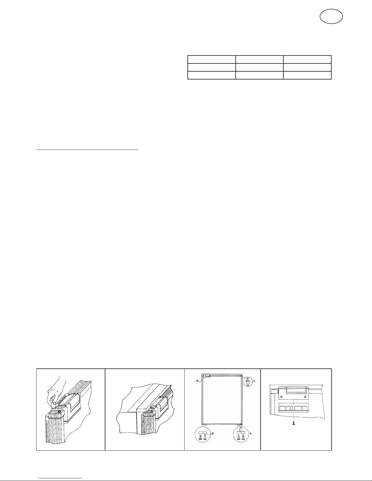
The fridge doors are hinged on the right hand side as standard. They
can be re-hinged to the other side by taking off the door, moving the
upper door hinge pin to the other side and also changing side of the
lower door hinge pin ttings. The door locking is re-positoned to the
other side of the door upper frame. It is fastened with three screws.
See g. 3 & 4.
Ventilation
It is very important that the compressor/condenser unit is well
ventilated and that cold air can enter at the bottom, pass behind
the fridge and warm air can leave at the top in the area where it is
mounted. The natural ow of air from below and upwards behind
the fridge can be increased by arranging ventilation openings at
the rear.
Fig. 1 Fig. 2
1
Fig. 3
Fig. 4
GB
Page 3
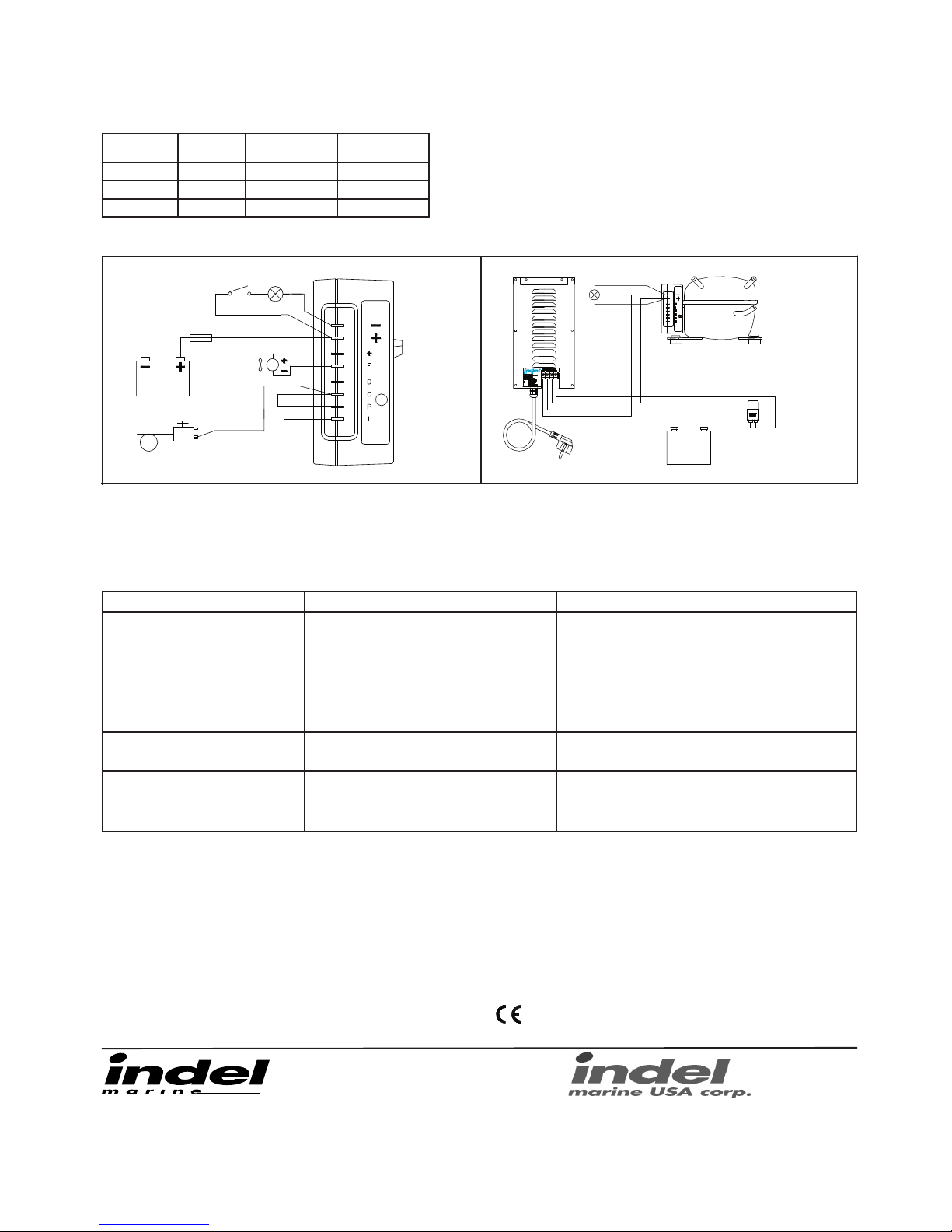
1. Electronic unit 12-24 volt
2. Battery
3. Fuse 15A-12V / 7.5A-24V
4. Converter 90-250VAC / 24VDC
5. Inner light 12/24 volt max 3 watt
Wiring diagram Cruise fridges and boxes Wiring diagram AC/DC Conveter
Fault Possible cause Action
Fridge not cold.
Compressor will not start.
No power supply.
Battery in poor condition.
Faulty thermostat.
Faulty electronic unit.
Check that power is present at terminal box. check fuse. Internal light
works?
Check all terminal connections and cables.
Inspect battery charging system.
Check thermostat. Bridge T-C, if compressor starts, thermostat is faulty,
replace. If compressor does not start, probably electronic unit is faulty.
Exchange electronic unit.
Compressor makes only short start attempts. Bad power supply, too low voltage or a voltage drop at start
attempts.
Discharged batteries.
Check cables and connections, possible verdigris, clean.
Charge batteries, run the engine or connect battery charger. Voltage shall
be above 11.0 volt at start attempts.
Compressor runs but no refrigeration generated. Loss of refrigerant. Leakage in pipes or evaporator.
Pipes blocked.
Mount service nipple on the compressor (refrigarators). Leak test, repair
possible leak, evacuate and re-ll refrigerant.
(All this to be made by refrigeration specialist)
Compressor runs long time but not generating
enough cold.
Bad ventilation. Condenser too warm.
Fan not working.
To much frost on evaporator.
Door not closing well.
Condenser blocked by dust.
Improve ventilation for compressor.
Re-place fan.
Defrost.
Check door position and door seal.
Clean condenser.
Fault nding chart
Cable area
mm²
Gauge Max cable length
in metres/ft 12 volt
Max cable length
in metres/ft 24 volt
2.5 12 2.5 / 8 5 / 16
4 10 4 / 13 8 / 26
6 10 6 / 19 12 / 39
Technical data
Voltage: 12/24 volt
Power consumption: 2.5 - 6 A (depending on model and compressor speed setting)
Average power consumption: 0.6 - 2.5 A (depending on model)
Freezer models; 2 - 2.5 times higher average power consumption
Compressor: Danfoss BD35F alt. BD50F (depending on model)
Refrigerant: R134a (lled amount written on type sticker inside fridge or outside box housing)
Fuse: 12 volt - 15 A, 24 volt - 7.5 A
Battery protection: Cut-out at 9.6 volt (21.3), cut-in at 10.9 volt (22.7)
Isotherm refrigerators and freezers fullls EMC directives, CE-marked
IT-61019 S. Agata Feltria (PU) - Italy
Phone +39 0541 848030
Fax +39 0541 848563
info@indelmarine.com www.indelmarine.com
www.isotherm.com
Fig. 5
Electrical connections/wiring
When connecting the fridge it is important that following points are
considered:
* Always use cables of sufcient area. The area in the following table
should be regarded as a minimum.
* Always connect the fridge directly to the battery or to the battery main
switch on the plus circuit. Do not connect it via the boats own control
panel or other diversions as this can cause a voltage drop in the power
supply. The system shall have a 15A fuse for 12 volt and a 7.5A in a 24
volt system. If a switch is tted this should be of a minimum 20 A type.
* Connect the red cable to the positive (+) terminal and the black to
the negtive (-) terminal. Always use proper type terminals or cable
connectors of sufcient size for the cable size selected.
* Do not connect the fridge direct to a battery charger. The battery
charger must be connected to the battery.
* See wiring diagrams.
5300 NW 12th Avenue unit #2
Fort Lauderdale, FL 33309, USA
Phone: +1 954 772 8355, +1 800 422 9711,
Fax: +1 954 772 3839
info@indelmarineusa.com www.indelmarineusa.com
TC
1
2
3
4
5
6
1. Electronic unit 12-24 volt
2. Battery
3. Fan
4. Thermostat
5. Fuse 15A-12V / 7.5A-24V
6. Inner light max 3W
Fig. 6000801
2 3
1
4
5
000796-4
isotherm
-
+
2
 Loading...