

Page 1
Installation & operating instructions
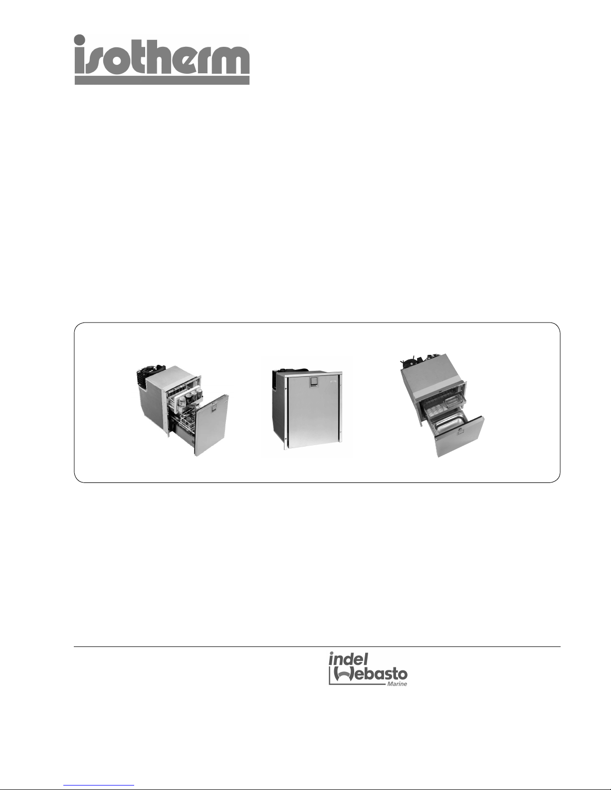
Isotherm INOX marine refrigerators
Type: DR 49 & DR 65
080429-LLG
DRman.us.ind
Indel Webasto Marine S.r.l.
Zona Artigianale
IT-61019 S. Agata Feltria (PU) - Italy
Te l +39 0541 848 030 Fax +39 0541 848 563
E-mail:info@indelwebastomarine.com
www.indelwebastomarine.com
Page 2

Installation & operating instructions
Table of contents
1 Introduction
1.1 General
1.2 Safety and precautions
1.3 Environmental markings
2 Operation
2.1 Tem perature setting thermostat
2.2 User tips
2.3 Defrosting
3 Maintenance
3.1 Battery voltage sensor
4 Installation instructions
4.1 Ventilation
4.2 Door front
4.3 Electrical connections
4.4 Electrical wire dimensions
4.5 Inner light
4.6 Wiring diagram
5 Tec hnical data
6 Trouble shooting
7 Installation dimensions
1
Page 3
1. Introduction
1.1 General
Isotherm refrigerators are specially designed to operate
in tough marine environments. They are fi tted with a fully
hermetic, leak-free compressor, they offer the lowest
possible power consumption and noise level. All models
are simple to install. They can withstand an angle of heel
up to 30°, for a short time. To ensure that your Isotherm
fridge operates as effi ciently as possible, please follow
these general guidelines:
• Unnecessary opening of the fridge door will increase
power consumption.
• Good ventilation of the compressor and condenser
unit will reduce power consumption.
• The electrical system should be in good condition.
Inspect batteries and charging levels regularly.
Always use a separate starter battery for the engine.
Follow carefully the guidelines regarding electrical
cable areas and fuse placements.
• Keep the inside of the fridge and freezer clean and
dry. Remove any water from condensation that may
have collected in the drip tray.
• Keep the door slightly open to air the refrigerator
when leaving the boat for any length of time.
• Clean the inside of the refrigerator with lukewarm
water and a mild detergent before taking the fridge
into operation the fi rst time.
For your own and others safety, read this fi rst.
Danger! When connected to mains power,
ensure that the power supply is equipped with
an earth safety automatic switch, a ”ground fault
circuit interrupter”.
Danger! Never touch bare electrical wiring
connected to the AC power supply.
Do not use the device if the connector cables
show visible damage.
Never connect battery charger direct to the
refrigeration system.
A battery charger must be connected to the
battery, never direct to the refrigeration system.
Danger! In addition to acid, a newly-charged
battery contains explosive gas.
Never cover the ventilation openings for the
compressor unit.
Refrigerant may never be let out in the air.
Repair of the refrigeration circuit must be done by
a certifi ed technician.
1.3 Environmental markings
This appliance is marked according to the European
directive 2002/96/EC on Waste Electrical and Electronic
Equipment (WEEE). By ensuring this product is disposed
of correctly, you will help prevent potential negative
consequences for the environment and human health,
which could otherwise be caused by inappropriate waste
handling of this product.
The symbol on the product, or on the documents
accompanying the product, indicates that this product
may not be treated as household waste. Instead it
shall be handed over to the applicable collection point
for recycling of electrical and electronic equipment.
Disposal must be carried out in accordance with local
environmental regulations for waste disposal.
For more detailed information about treatment, recovery
and recycling of this product,
please contact your local city offi ce,
your household waste disposal service
or the shop where you purchased the
product.
1.2 Safety and precautions
2
Page 4

2. Operation
The refrigerators are made for use at ambient temparures between 0°C/32°F and +43°C/107°F.
2.1 Temperature regulation thermostat
The refrigerator is fi tted with a manually operated
thermostat. This is turned clockwise to reduce
temperature and anti-clockwise to both increase
temperature and activate the on-off switch at the end
position, 0-position. A certain spring resistance is
recognized at the off position.
It is advisable to start with the thermostat in a medium
position. It is advisable to keep a temperature of 5-6°C/
41-43°F inside the refrigerator. Higher temperatures will
reduce storage time.
The ambient temperature infl uences the temperature
also inside the fridge. Avoid direct sunshine and other
heat sources close to the refrigerator.
The thermostat control knob is placed inside the
refrigerator, see description below.
3. Maintenance
The Isotherm DR refrigeration systems have a fully
hermetic closed cooling system and do not require any
maintenance or refi lling of refrigerant.
The compressor is of mobile type and has a very high
effi ciency and an outstanding life-time. The refrigerator
shall be left in the boat during the winter. (If the
temperature is below freezing point, the compressor may
not start). The maintenance is reduced to periodically,
not less than a year, cleaning of the condenser from
dust. Use a soft brush and no sharp tools. Keep the
cabinet inside clean. Use lukewarm water and a mild
detergent for cleaning the inside. Put the doors, during
not in operation periods, in their
slightly open ventilation position.
Thermostat inside on
vertical wall.
3.1 Battery voltage sensor
To protect the batteries from becoming completely
discharged, a battery voltage sensor switches off the
compressor automatically at the following levels:
System voltage V Cut out V Cut in V
12 9.6 (10.4) 10.9 (11.7)
24 21.3 (22.8) 22.7 (24.2)
If the bridge between C and P is cut off, values within the
() are valid.
3
2.2 User tips
- Load the food inside the refrigerator in such a way, air
can circulate to equalize the temperature.
- Do not cover the shelves with glass or paper etc.
- To reduce the amount of ice building up in the
evaporator, cover all liquids and moist food.
- Let all hot foods cool well before putting them into the
refrigerator.
2.3 Defrosting
The evaporator is working on below freezing
temperatures and will form frost and ice from humidity in
the air. The humidity increases with higher outside
temperature, with storage of non sealed fresh food and
liquids and the time the door is kept open. Defrosting
shall be made when the frost layer is more than 4 mm /
1/8” thick.
Set the thermostat in OFF position or switch off on the
ASU control panel. Store the foodstuff and the liquid as
cold as possible during the defrosting process.
Do not use sharp metal tools to remove frost or
ice. Do not re-start until the refrigerator is completely
defrosted, cleaned and dried. Empty and clean also the
plastic drip tray below the evaporator. Place towels in the
bottom of the refrigerator to collect melt water.
4 Installation instructions
Many boats have a space which is intended for a fridge.
The Isotherm Cruise fridge has been designed to suit the
general dimensions normally used for this purpose.
The compressor should normally stand upright in the
boat, but will operate at an angle of heel up to 30° and
for short periods even more.
The INOX type refrigerators have a fl ush mounting
frame, three side frame, as standard.
4.1 Ventilation
It is very important that the compressor/condenser unit is
well ventilated and that cold air can enter at the bottom,
pass behind the fridge and warm air can leave at the
top in the area where it is mounted. The natural fl ow of
air from below and upwards behind the fridge can be
increased by arranging ventilation openings at the rear.
Make sure there is a free area of 15 - 23 sq.in. below
and behind the refrigerator to allow ventilation air to pass
behind from below.
See fi g.
Page 5

4
4.4 Wire dimensions
Cable
area mm²
Wire
gauge #
Max cable
length in m/ft.
12V
Max cable
length in m/ft,
24V
2.5 12 2,5 / 8 5 / 16
4 12 4 / 13 8 / 26
6 10 6 / 33 12 / 66
4.3 Electrical connections/wiring
When connecting the refrigerator electrically, it is
important that following points are considered:
Always use cables of suffi cient area. The area in the
following table should be regarded as a minimum.
* Always connect the refrigerator directly to the battery
or to the battery main switch on the plus circuit. Do
not connect it via the boats own control panel or
other diversions as this can cause a voltage drop in
the power supply. Use the included fuse holder with
a 15A fuse. Use 7.5A fuse in a 24 volt system. The
fuse shall be mounted on the plus cable.
4.5 Inner light
The refrigerators have inner light (LED) mounted in the
top of the cabinet.
4.2 Door front panel
The INOX models have doors in stainless steel and do
not have exchangeable door fronts.
4.6 Wiring diagram
12-24 VDC
1. Electronic unit 12/24 volt
2. Battery
3. Fan
4. Thermostat
5. Fuse 15A-12V / 7,5A-24V
6. Light LED
1
2
3
4
5
6
001284
AC/DC, 100-240 VAC & 12-24 VDC
* Connect the red cable to the positive (+) terminal
and the black to the negative (-) terminal. Use tab
type terminals for the connection to the electronic
unit and other cable connectors of suffi cient size for
the cable size selected.
* Do not connect the refrigerator direct to a battery
charger. The battery charger must be connected to
the battery.
001286
Page 6

5
5 Technical data
Voltage 12 or 24 volt DC / 100-240 volt AC
Power consumption when compressor is running: DR 49 & 65: 5 A at 12 V (half at 24 V)
Average consumption:
Average consumption measured at +6°C/43°F in the refrigerator
and 22°C/72°F ambient temperature.
The average consumption is much dependent on the way the
fridge is used and how well the ventilation
is working.
DR 49: 0,8 A at 12 V
DR 65: 0,9 A at 12 V
Compressor: Danfoss BD35F
Refrigerant: R134a, fi lling amount is printed on the sticker
inside the fridge.
Fuse: 15 A for12 volt or 7,5 A for 24 volt respectively.
Isotherm refrigerators fulfi l valid EMC directives and are CE-marked.
6 Fault fi nding
Fault Possible cause Action
Fridge not cold, compressor will
not start.
No power supply.
Battery in poor condition.
Faulty thermostat.
Faulty electronic unit.
Check that power is present at electronic unit.
Check fuse.
Check polarity on connectors and cables.
Bridge the thermostat over T-C, see wiring diagram. If compressor starts, this indicates a faulty
thermostat. If the compressor does not start, this
indicates a faulty electronic unit or compressor.
Contact an authorized service agent.
A possible leak in the cooling system, contact an
authorized service agent.
Compressor makes only short
start attempts.
Bad power supply, too low voltage or
voltage drop at start attempts.
Discharged batteries.
Check cables, terminals and other connections,
possible verdigris or corrosion, Clean.
Charge batteries, run the engine or connect a battery charger. Voltage must be kept above 11.0 V at
start attempts.
Compressor runs but no refrigeration generated.
Loss of refrigerant. Leakage in pipes or
evaporator.
Pipes blocked.
Pressure and leak test. Check for pipe damages.
Repair possible leak, evacuate and re-fi ll refrigerant. (All this to be made by refrigeration specialist).
Compressor runs long time but
not generating enough cold.
Bad ventilation. Condenser too warm.
Cooling fan not working
To o much frost on evaporator.
Door not closing well.
Condenser blocked by dust.
Improve ventilation for compressor.
Re-place fan.
Defrost.
Check/adjust door position and door seal.
Clean condenser.
Fuse blows. Wrong fuse size.
Faulty electronic unit.
Check fuse, 15 A-12 V / 7,5 A-24 V
Exchange electronic unit.
If a complicated fault does occur, such as requiring specialist assistance, please contact
Indel Webasto Marine USA Inc. or your local marine distributor for advice.
Page 7

6
Type B * H * D D - AC/DC
DR 49 INOX 15-3/4 20-7/8 19-7/8 20-7/8
DR 65 INOX 18-7/16 20-7/8 20-7/8 21-3/4
*) W x H = day opening, min dimensions
More detailed drawings of the refrigerators can
be seen on: www.indelwebastomarine.com
7 Installation dimensions
Page 8

Notes:
Indel Webasto Marine S.r.l.
Zona Artigianale
IT-61019 S. Agata Feltria (PU) - Italy
Te l +39 0541 848 030 Fax +39 0541 848 563
E-mail:info@indelwebastomarine.com
www.indelwebastomarine.com
Indel Webasto Marine USA Inc.
3400 Gateway Drive, Unit # 107
Pompano Beach, FL - 33069
Te l +1 954 984 8448 Fax +1 954 979 2533
E-mail:info@indelwebastomarineusa.com
www.indelwebastomarineusa.com
 Loading...