

Isotherm CR 195, CR 195 Stainless Steel-INOX Installation And Operating Instructions Manual
Page 1
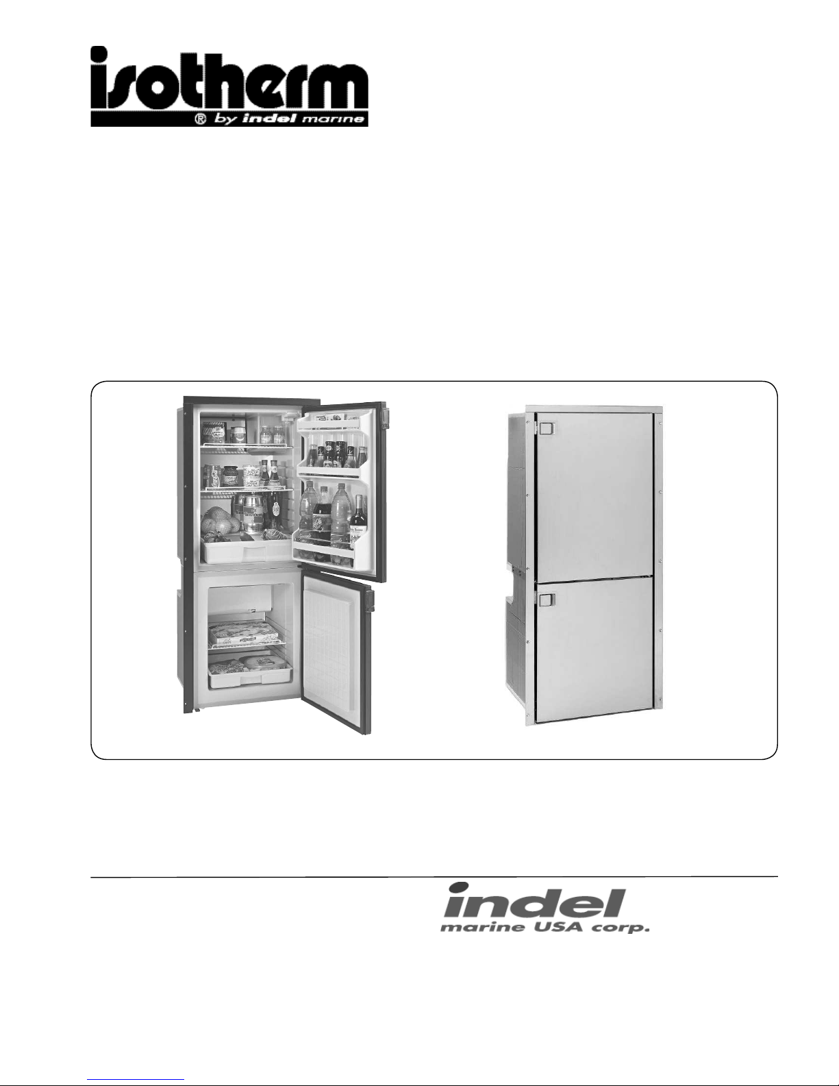
Marine Refrigerator/freezer CR 195
& CR 195 Stainless Steel-INOX
Installation and operating instructions
Indel Marine USA, Inc.
3400 Gateway Drive
Unit 107
Pompano Beach, FL 33069
Te l +1 954 984 8448, +1 800 422 9711
Fax +1 954 979 2533
E-mail: info@indelmarineusa.com www.indelmarineusa.com
Page 2

Contents
1 Introduction
1.1 General
1.2 Safety and precautions
1.3 Environmental markings
2 Operation
2.1 Temperature setting
2.2 User tips
2.3 Defrosting
3 Maintenance
3.1 Battery voltage sensor
4 Installation instructions
4.1 Ventilation
4.2 Door front
4.3 Electrical connections
4.4 Electrical wire dimensions
4.5 Inner light
5 Technical data
6 Trouble shooting
7 Installation dimension drawings
1
Page 3
1 Introduction
1.1 General
Isotherm refrigerators are specially designed to operate in tough
marine environments. They are fi tted with a fully hermetic,
leak-free compressor, they offer the lowest possible power
consumption and noise level. All models are simple to install.
They can withstand an angle of heel up to 30°, for a short time.
To ensure that your Isotherm fridge operates as effi ciently as
possible, please follow these general guidelines:
• Unnecessary opening of the fridge door will increase power
consumption.
• Good ventilation of the compressor and condenser unit will
reduce power consumption.
• The electrical system should be in good condition. Inspect
batteries and charging levels regularly. Always use a separate
starter battery for the engine. Follow carefully the guidelines
regarding electrical able areas and fuse placements.
• Keep the inside of the fridge and freezer clean and dry.
Remove any water from condensation that may have collected
in the plastic baskets.
• Keep the door slightly open to air the refrigerator and freezer
when leaving the boat for any length of time. (Fig. 1 and 2)
1.2 Safety and precautions
For your own and others safety, read this fi rst.
I.3 Environmental markings
The symbol on the product, or on the documents
accompanying the product, indicates that this product may not
be treated as household waste. Instead it shall be handed over
to the applicable collection point for recycling of electrical and
electronic equipment. Disposal must be carried out in accordance
with local environmental regulations for waste disposal.
For more detailed information about treatment, recovery and
recycling of this product, please contact your local city offi ce,
your household waste disposal service or the shop where you
purchased the product.
Danger! Only connect the device to a 110 - 230 Volt power
outlet installed according to regulations, being accordingly
fused.
When connected to mains power, ensure that the power
supply is equipped with an earth safety automatic switch, a
”ground fault circuit interrupter”.
Danger! Never touch bare electrical wiring connected to
the AC power supply.
Do not use the device if the connector cables show visible
damage.
Never connect battery charger direct to the refrigeration
system.
A battery charger must be connected to the battery, never
direct to the refrigeration system.
Danger! In addition to acid, a newly-charged battery
contains explosive gas.
Never cover the ventilation openings for the compressor
unit.
Refrigerant may never be let out in the air.
Repair of the refrigeration circuit must be done by a
certifi ed technician.
2 Operation
2.1 Temperature setting
The refrigerator and freezer units are fi tted with manually
operated thermostats. The thermostat control knob is placed
inside the refrigerator compartment to the right and the freezer
compartment has the thermostat also to the right.
The thermostat is turned clockwise to reduce temperature and
anti-clockwise to both increase temperature and activate the
on-off switch at the end position, 0-position. A certain spring
resistance is recognized at the off position.
It is advisable to start with the thermostat in a medium position,
do not set the thermostat in the coldest position. Remember
that the thermostat settings are effected by variations in ambient
temperature, the quantity of stored food, its position and how
often the doors are opened.
If the ambient temperature is very high the compressor
might work continuously causing the occasional formation
of frost. If this occurs the thermostat knob should be turned
to a lower number = warmer setting, to allow the compressor
to cycle on and off.
If suffi cient temperature can not be reached with thermostat/
compressor still cycling, it is a sign of improper ventilation on the
rear side of the refrigerator/freezer.
When the refrigerator or freezer is switched on after it has been
out of use, it will take several hours until the refrigeration and
freezer temperatures are reached.
To reduce humidity and the consequent increase of frost, never
place liquids in unsealed containers in the refrigerator.
2.2 User tips
- The freezer compartment is meant for storage of pre-frozen
food. It has also capacity for deep freezing.
- Start up the refrigerator if possible 6-8 hours before it shall be
loaded with food.
- When making ice in the ice tray, place it direct on the upper
shelf in the freezer and put nothing on top of the ice tray. For
quicker ice-making, turn the thermostat to coldest position.
- Load the food inside the refrigerator in such a way, air can
circulate to equalize the temperature.
- Do not cover the shelves with glass or paper etc.
- To reduce the amount of ice building up inside the fridge,
cover all liquids and moist food.
- Let all hot foods cool well before putting them into the
refrigerator.
2.3 Defrosting
Defrosting shall be made when the frost layer is more than 1/8”
thick. Set the thermostats in OFF position. Store the foodstuff
and the liquid as cold as possible during the defrosting process.
Do not use sharp metal tools to remove frost or ice. Do not restart until the refrigerator and freezer are completely defrosted,
cleaned and dried. Empty and clean also the plastic tray in the
lower part of the compartments.
2
Page 4
4.2 Door front panel
The front panels on the doors can be replaced or additional
standard front panels in white, teak, mahogany or cherry can be
mounted on top of the standard panel.
Use a screwdriver or a knife as a lever and pull off the lower door
profi le. Unscrew the three screws holding the door lock.
Mount the extra panel on top of the existing one, fasten the door
lock again and push in the lower door profi le.
See fi g. 5 and 6.
The INOX model has doors in stainless steel and it has not
exchangeable door fronts.
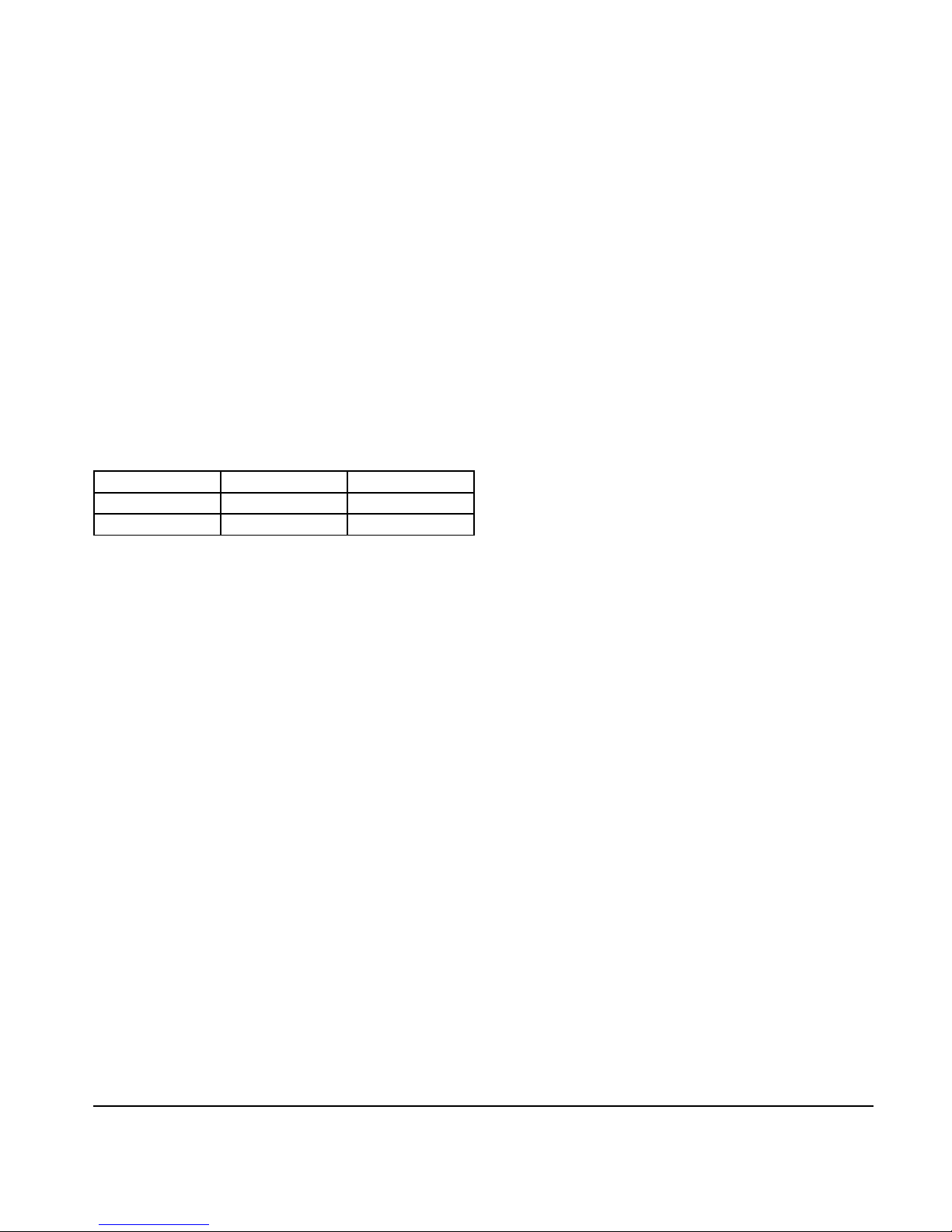
3.1 Battery voltage sensor
To protect the batteries from becoming completely discharged, a
battery voltage sensor switches off the compressor automatically
at the following levels:
System Voltage Cut-out Cut-in
12 V 9.6 V (10.4) 10.9 V (11.7)
24 V 21.3 V 22.7 V
If the bridge between C and P is cut off, values within the () are
valid.
4.3 Electrical connections/wiring for power supply
CR 195 is available in two versions, one is equipped with
Danfoss 12-24 VDC electronic units and the other is equipped
with AC-DC electronic units. It is important that following points
are considered:
DC (12 or 24 volt)
The electronic unit must always be connected direct to the
battery poles. Connect the positive/plus to + and the negative/
minus to - on the battery. Without proper positive/negative
connections, the electronic unit will not work - it is protected
against reverse battery connection.
For protection of the installation, a fuse for each compressor
must be mounted in the positive cable as close to the battery as
possible.
A 15A fuse for a 12V power supply and a 7.5A fuse for a 24 volt
circuit are recommended. If a breaker box connection is used, it
should be rated to a minimum of 30A.
Avoid extra junctions in the power supply system to prevent
voltage drop from affecting the battery protection setting.
The light is connected to battery power on the electronic unit and
the bulb must be selected 12 or 24 volt. Both types are included
in the delivery.
See wiring diagram fi g. 8 valid for both compressors.
AC (100-240 volt)
The live and neutral wires must be connected to the terminals
marked L and N on the electronic unit. Nominal voltages from
100 to 240 VAC 50/60 Hz. Upper safety cut out limit is 270 VAC
and lower limit is 80 VAC.Earth connection is to be placed on the
compressor foot near the electronic unit. There is a hole drilled
in the foot for this purpose, use a 5/32” screw and nut and a ring
cable shoe on the wire.
Connection of mains power plug must fulfi l valid electrical safety
regulations and properly fused with 4A. Wire gauge, AWG18.
General AC/DC
Both AC an DC power supply can be connected to the electronic
unit at the same time. AC will be preferred power supply source
if that is the case. If the AC power supply is disconnected, a
time delay of 1 minute will be activated before the compressor
continuous on DC power supply. If AC power supply is
established there will be no delay in compressor operation, when
power supply is shifting from DC to AC.The light power supply is
connected to A and C. The output voltage on A and C is always
regulated to 12 VDC. A 12 VDC bulb must be used for both 12
and 24 VDC power supply systems.
See wiring diagram fi g. 9 valid for both compressors but the
freezer does not have inner light.
3 Maintenance
The Isotherm refrigeration systems have a fully hermetic closed
cooling system and do not require any maintenance or refi lling of
refrigerant.
The compressor is of domestic type and has a very high
effi ciency and an outstanding life-time. The refrigerator/freezer
shall be left in the boat during the winter. (If the temperature
is below freezing point, the compressor may not start). The
maintenance is reduced to periodically, not less than a year,
cleaning of the condensers from dust. Use a soft brush and no
sharp tools. Keep the cabinet inside clean. Use lukewarm water
and a mild detergent for cleaning the inside. Put the doors,
during not in operation periods, in their slightly open ventilation
positions. Release the catch on the door for this purpose with a
coin or a small screwdriver (fi g. 1 and 2) (not valid for Stailess
steel version, “INOX”). Ta ke out the bulb from the internal light to
avoid power consumption or switch off a main switch if there is
one installed connected to the refrigerator/freezer power supply.
(Fig 3 and 4)
4 Installation instructions
Many boats have a space which is intended for a fridge. The
Isotherm Cruise fridge has been designed to suit the general
dimensions normally used for this purpose.
The compressor should normally stand upright in the boat, but
will operate at an angle of heel up to 30° and for short periods
even more. The compressors on CR 195 are attached by its rear
side.
The refrigerator/freezer unit has a three side mounting fl ange to
fasten the unit in place. It must also be standing on its feet.
See installation dimensions on fi g. 10.
Avoid mounting close to a heat source, like gas ovens and
heaters. Also avoid a position allowing direct sunshine on the
refrigeration/freezer unit.
The mounting positon should be dry and protected from
splashing water.
4.1 Ventilation
It is very important that the compressor/condenser units
are well ventilated and that cold air can enter at the bottom,
pass behind the fridge/freezer and warm air can leave at the
top in the area where it is mounted. The natural fl ow of air
from below and upwards behind the fridge can be increased
by arranging ventilation openings at the rear.
Make sure there is a free area of 23 - 28 sq.in. below and behind
the refrigerator/freezer to allow ventilation air to pass behind from
below. See fi g 5.
3
Page 5
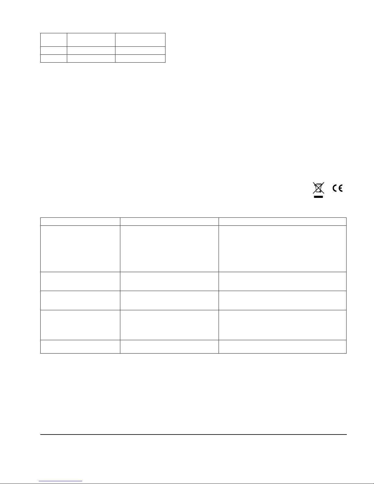
AWG Max cable length
in ft 12 volt
Max cable length
in ft 24 volt
12 8 16
10 19 38
The wire dimensions are valid for each compressor.
4.4 Cable area selection chart
5 Technical data
Voltage: DC type 12/24 VDC
AC/DC type 100-240VAC - 12/24VDC
Current consumption: ~ 10 A on 12V (when the compressors are running)
Average current consumption: 4.6 - 8.0 A on 12V (depending on ambient temperature 70 - 95°F)
Current consumption in ”off”-pos.: 14 mA on 12 V
Humidity: Max 90%
Ambient temperature: Max 110°F
Compressor: Danfoss BD50F
Refrigerant: R134a (fi lled amount written on type sticker inside the fridge compartment)
Fuse: 12 volt - 15 A, 24 volt - 7.5 A for each compressor
Battery protection: Cut-out at 9.6 volt (21.3), cut-in at 10.9 volt (22.7)
Isotherm refrigerators and freezers fulfi lls EMC directives, CE-marked
Fault Possible cause Action
Fridge not cold.
Compressor will not start.
No power supply.
Battery in poor condition.
Faulty thermostat.
Faulty electronic unit.
Check that power is present at terminal box. check fuse.
Internal light works?
Check all terminal connections and cables.
Inspect battery charging system.
Check thermostat. Bridge T-C, if compressor starts, thermostat is faulty, replace. If compressor does not start, probably
electronic unit is faulty.
Exchange electronic unit.
Compressor makes only short start
attempts.
Bad power supply, too low voltage or a voltage drop at start attempts.
Discharged batteries.
Check cables and connections, possible corrosion, clean.
Charge batteries, run the engine or connect battery charger.
Voltage shall be above 11.0 volt at start attempts.
Compressor runs but no refrigeration generated.
Loss of refrigerant. Leakage in pipes or
evaporator.
Pipes blocked.
Mount service nipple on the compressor (refrigerators). Leak
test, repair possible leak, evacuate and re-fi ll refrigerant.
(All this to be made by refrigeration specialist)
Compressor runs long time but not
generating enough cold.
Bad ventilation. Condenser too warm.
Fan not working.
To much frost on evaporator.
Door not closing well.
Condenser blocked by dust.
Improve ventilation for compressor.
Replace fan.
Defrost.
Check door position and door seal.
Clean condenser.
Fuse blows. Wrong fuse size.
Faulty electronic unit.
Check fuse 15A/12V or 7.5A-24V.
Replace electronic.
6 Fault fi nding chart
4.5 Inner light
The refrigerator compartment has inner light mounted in the top
of the cabinet.
Be sure the right type of bulb, 12 or 24 volt, is mounted before
the refrigerator is powered. Both 12 and 24 volt bulb are included
in the delivery. Max 3W bulb is to be used.
When replacing the bulb, push the light glass assembly downwards with the on-off push pin. Replace the bulb and push back
the light assembly into the plastic housing.
See fi g. 3 and 4.
4
Page 6

Fig. 1 Fig. 2
Figures
Fig. 3 Fig. 4
Fig. 5 Fig. 6 Fig. 7
Ventilation principals
Wiring diagram for CR 195 - 12/24 VDC
001084
Fig. 8
Note!
No light in
freezer compartment.
5
Page 7
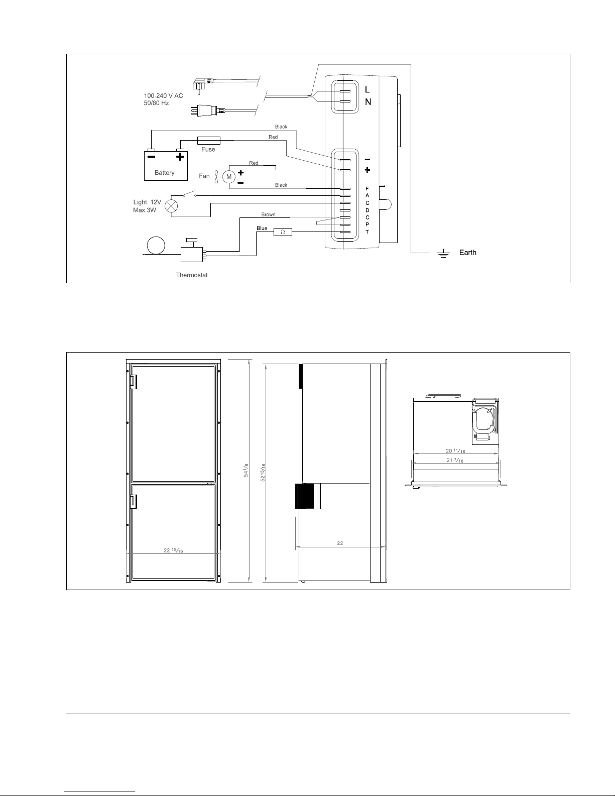
7 Installation dimensions CR 195 & CR 195 INOX
Wiring diagram for CR 195 AC/DC
000941-2
Fig. 9
Fig. 10
Note!
No light in
freezer compartment.
6
2008-01-07/LLG
CR195u
 Loading...