

Page 1

BI 41
Installation and operation manual
Einbau- und Bedienungsanleitung
Installations- och bruksanvisning
Indel Webasto Marine S.r.l.
Zona Artigianale
IT-61019 S. Agata Feltria (PU), Italy
Te l: +39 0541 848 030
Fax: +39 0541 848 563
E-mail: info@indelwebastomarine.com
www.indelwebastomarine.com
Page 2

Notes:
Page 3

Isotherm built-in box
41 litres
General
Specially designed to operate in tough marine
environments, Isotherm fridge and freezer boxes are
outstanding in both performance and reliability. Fitted
with a fully hermetic, leak-free compressor, they offer
the lowest possible power consumption and noise
level. All models are easy to install. BI41 is used in
the fi rst hand as a refrigeration box, but can reach
temperatures down to -10°C/14°F. The box can stand
an angle of heel up to 30°, for a short time even
more. To ensure that your Isotherm box operates as
effi ciently as possible, please follow these general
guidelines:
* Unnecessary opening of the lid will increase
power consumption.
* Good ventilation of the compressor and
condenser unit will reduce power
consumption.
* The electrical system should be in good
condition. Inspect batteries and charging
level regularly. Always use a separate starter
battery for the engine. Follow carefully the
guidelines regarding electrical cable areas and
fuse placements.
* Keep the inside of the box clean and dry.
Keep the lid slightly open, to air the box when
leaving the boat for any length of time.
* Keep the drainage in the box closed during
normal operation, if such is mounted.
Operation
Te mperature setting
The boxes are fi tted with a manually operated,
infi nitely-variable thermostat to operate the box within
refrigeration temperatures. This is turned clockwise
to reduce temperature and anti-clockwise to increase
temperature.
Turn the thermostat knob to the off-position, maximum
anti-clockwise, to stop the unit working.
The thermostat knob is placed inside the box.
Defrosting
Defrosting shall be made when the frost layer is more
than 3-4 mm thick. Turn off the unit with the thermostat
put into off-position. Store the foodstuff and the bottles
as cold as possible during the defrosting. Do not use
sharp metal objects to remove frost or ice. Do not restart until the box is completely defrosted and dried. Do
not forget to close the drainage if such is mounted,
Maintenance
The Isotherm boxes have a fully hermetic closed
cooling system and do not require any maintenance or
refi lling of refrigerant. The compressor is of domestic
type and has a very higheffi ciency and an outstanding
life-time. The box shall be left in the boat during the
winter. (If the temperature is below freezing point, the
compressor will not start).
The maintenance is reduced to periodically, not less
than a year, cleaning of the condenser from dust, on air
cooled units. Use a soft brush and no hard objects.
Keep the inside of the box. Use lukewarm water and
a mild cleaner for the inside. Put the lid, during not in
operation periods, in a slightly open ventilation position.
See also the Isotherm SP and Magnum installation
instructions.
Battery voltage sensor
To protect the batteries from becoming completely
discharged, a battery voltage sensor switches off the
compressor automatically at the following levels:
System voltage Cut-out Cut-in
12 9.6 alt. 10.4 10.9 alt. 11.7
24 21.3 alt. 22.8 22.7 alt. 24.2
Safety instructions and environment
- When connected to shore power, ensure that the
power supply is equipped with an automatic earth
leak switch. Danger!
- Never touch bare electric wiring connected to the
mains supply. Danger!
- Never connect a battery charger direct to the
refrigeration system. A battery charger must be
connected to the battery.
- In addition to acid, a newly-charged battery contains
explosive gas. Danger!
- Never open the refrigerant circuit except by the re operable quick couplings which are of self sealing
types and designed for this purpose.
- Never cover up the ventilation system for the
compressor unit.
- The refrigeration unit must be disposed by a
refrigeration specialist for correct recycling of
components and care taking of the refrigerant.
This appliance is marked according to the European
directive 2002/96/EC on Waste Electric and Electronic
equipment /WEEE). By ensuring this product is
disposed of correctly, you will help prevent potential
negative consequences for the environment and
human health, which could otherwise be caused by
inappropriate waste handling of this product.
The symbol on the product, or on the
documents accompanying the product, indicates that
this product may not be treated as household waste.
Instead it shall be handed over to the applicable
collection point for recycling of electrical and electronic
equipment. Disposal must be carried out in accordance
with local environmental regulations for waste disposal.
For more detailed information about treatment,
recovery and recycling of this product, please contact
your local city offi ce, your household waste disposal
service or the shop where you purchased the product.
GB
Page 4

Fault fi nding chart
Fault Possible cause Action
Box not cold. Compressor will not start.
Compressor starts but does not cool
the box.
Check that power is present at electronic unit.
Chech fuse.
Check polarity on connectors and cables.
Bridge the thermostat over T-C, see wiring diagram.
If compressor starts, this indicates a faulty thermostat.
If the compressor does nopt start, this indicates a faulty electronic
unit or compressor.
Contact an authorized service agent.
A possible leak in the cooling system, contact an autorized service
agent.
If a complicated fault does occur, such as those requiring specialist assitance, pleas contact Indel Marine S.r.l. Italy or your
local marine distributor for advise.
Indel Webasto Marine S.r.l.
Te l. +39 0541 848 030
Fax +39 0541 848 563
E-mail: info@indelwebastomarine.com
Installation instructions
Mount the box carefully and safe. It is vitally important,
on air cooled units, that the compressor and the
condenser are well ventilated and that cold air can
enter from below and warm air can leave the space
around the compressor unit. (Warm air is leaving
upwards).
Do not install the box close to warm areas as the stove,
heater or the engine.
See the separate additional installation instructions for
Isotherm SP when the refrigeration unit is equipped
with an SP through hull fi tting/heat exchanger and also
the separate installation instructions valid for boxes
having a “Magnum” compressor unit water cooled with
water pump.
Electrical connections
When connecting the box electrically, it is important
that following points are considered:
Always use cables of suffi cient area. The area in the
following table should be regarded as a minimum.
Wire area
mm² AWG
Max wire length
12V m / ft
Max wire length
24V m / ft
2.5 12 2.5 / 8 5 / 16
4 10 6 / 18 12 / 32
6 10 10 / 32 20 / 64
* Always connect the box directly to the battery or
to the battery main switch on the plus circuit. Do not
connect it via the boats own control panel or other
diversions as this can cause a voltage drop in the
power supply. Use the included fuse holder with a 15A
fuse. Use 7.5A fuse in a 24 volt system. The fuse
shall be mounted on the plus cable.
* Connect the red cable to the positive (+) terminal
and the black to the negative (-) terminal. Use tab
type terminals for the connection to the electronic
unit and other cable
connectors of suffi cient size for the cable size
selected.
* Do not connect the box direct to a battery charger.
The battery charger must be connected to the
battery.
Page 5
Technical data
Voltage: 12/24 Volt
Power consumption: Running compressor: 4 A (half for 24 V system).
Average consumption: 12 Volt: approx. 0.7 A (half for 24 V system) at +6°C in the
box and 22°C ambient temperature.
Compressor: Danfoss BD35F
Refrigerant: R134a
Fuse: 15 A for 12 V/7.5A for 24 V
Type designations: 3041BA2A00000 Air cooled compressor
3041BA2A00006 Air cooled compressor, Pipe with couplings and Click-on bracket
3041CA2B00000 SP-water cooled
Dimensions: Height 465 mm (625 incl. compressor), Width 340 mm, Deep 500 mm
Weight: 19 kg
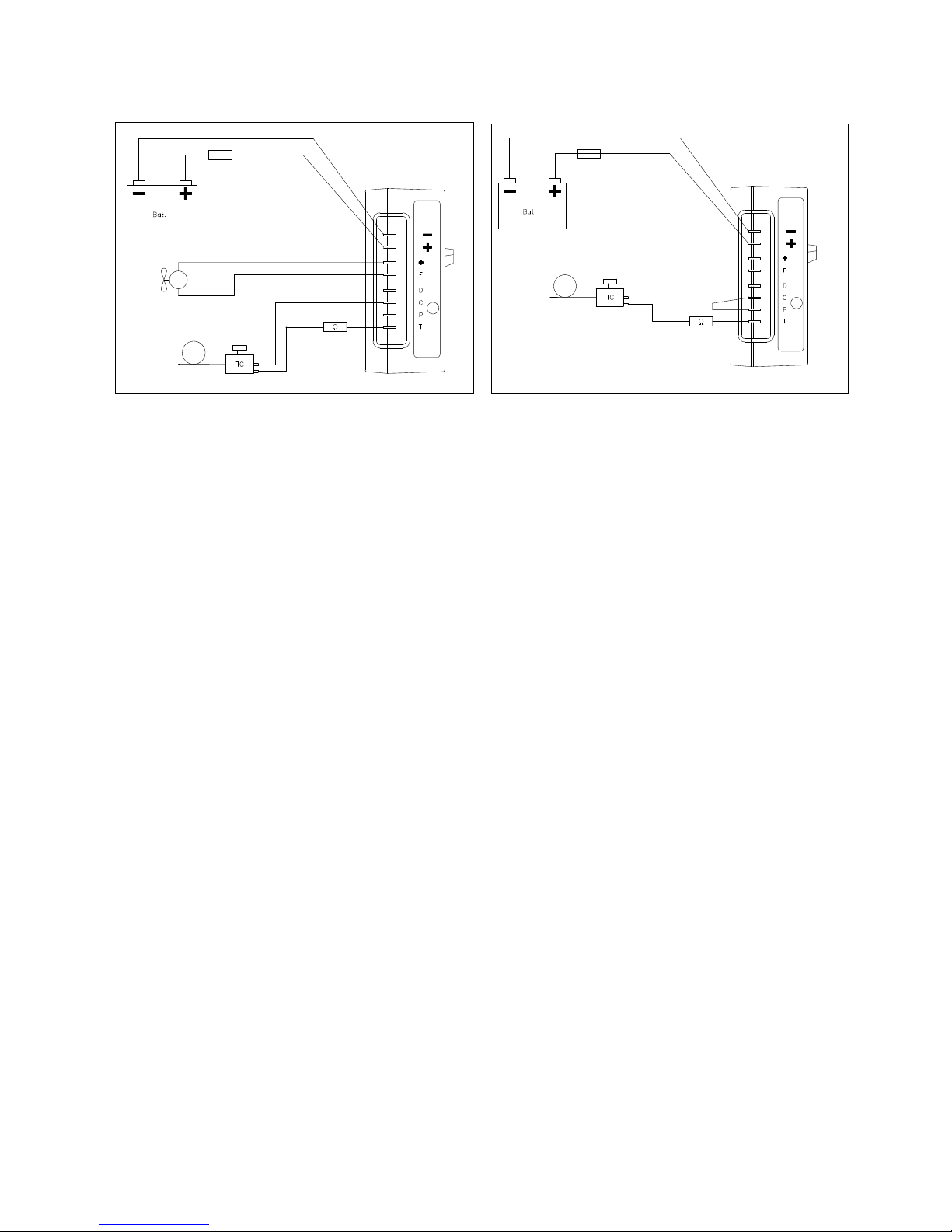
Wiring diagram
Air cooled Water cooled SP
Brown
Blue
Black
Red
Red
Black
Red
Black
Brown
Blue
000889-2
000890-2
Page 6

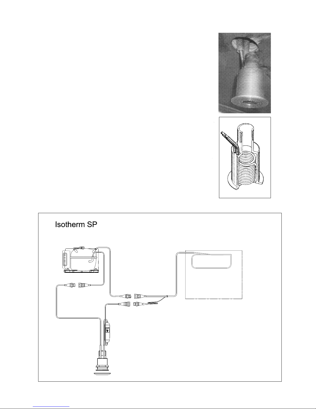
Isotherm SP Installation instructions
General
Isotherm SP is a sea water cooled refrigeration system for
sailing yachts and power boats. This unique system means
reduced power consumption and noise level. It has no fan
or pump. The sea water cooled skin fi tting/heat exchanger
replaces the air cooled condenser and cooling fan. The
heat is transferred directly to the surrounding water instead
of being circulated as hot air inside the boat.
Description
The special skin fi tting with its integrated condenser/heat
exchanger is mounted in the hull and is made of salt water
resistant brass with the heat exchanger coil in copper-nickel
alloy and replaces the existing skin fi tting for the sink drainage.
The connection pipes to the compressor have a length of 1
meter and are equipped with quick couplings. The couplings
can be opened and closed without loss of refrigerant. A fi lter
dryer is mounted approx. 20 cm (7¾”) above the skin fi tting
on the return pipe. A 1¼” ball valve should be mounted on
the skin fi tting.
Important! The hose between the sink and the ball valve shall be a minimum
of ø 38 mm (1½”). The skin fi tting is normally kept clean due to the constant
movement of the water and lack of sunlight. During sailing or motoring the
water will fl ash the fi tting and the heat exchanger coil rapidly, which will keep
it clean from marine growth. The skin fi tting shall be equipped with the zinc
anode on the outside and which is included in the delivery.
Operation
Always keep the ball valve open to ensure a satisfactory function.
If the ball valve is closed and the boat is in harbour, the fridge will operate at
a reduced cooling level.
During sailing or motoring the fridge will operate better but not to its full
potential with a closed valve. When the boat is on shore, the fridge system
will operate at a reduced level, in this case the ball valve must be kept open
to allow air ventilation through the hose and the sink.
Maintenance
When necessary clean the through hull fi tting, do not use sharp or hard tools, a brush will be enough. In a tropical
environment, cleaning of the fi tting has to be made more often. If necessary, the threaded bottom entrance
washer can be removed for better access to the heat exchanger coil.
Corrosion: Galvanic corrosion can often take place on board when the boat is surrounded by salt water and
should be carefully checked. This type of corrosion takes place depending on various electrical potential between
different devices. When two different metals are placed under water and connected to each other, electricity will
start to run. To prevent metal damages on parts under water, sacrifi ced anodes made of zinc are installed. Zinc is
a less noble metal compared to other materials used and will therefore be sacrifi ced.
All Isotherm refrigeration units have the plus and minus power supply separated from all chassis parts. Isotherm
SP has a skin fi tting in direct contact with the sea water and has as standard a zinz anode. The brass in the fi tting
is dezincifi cation and salt water resistant as well as the Cu/Ni condenser pipes and the soldering silver. The zinc
anode on the fi tting shall be inspected regularly and replaced as soon as half or more of the zinc is used. If it
is affected to a high degree and not lasting more than one season or part of a season, the electrical system on
board must be carefully checked to fi nd the reason for the galvanic or stray-current corrosion.
Make sure that the refrigeration system is connected to the electrical system in such a way, it cannot be
connected to the shore grounding when shore power is connected.
It is recommended to use an insulation transformer in the shore power system, to always be sure, boat and shore
grounding is separated.
When the boat is equipped with a central bonding system, the SP skin fi tting shall be connected to this with a 6
mm² copper cable. On the skin fi tting, there is a M5 hole for this purpose.
Page 7
Mounting
First of all, plan the installation!
The skin fi tting is to be mounted in the hull instead of existing fi tting for
the galley sink waste water. The hole in the hull shall have a diameter of
60 mm (2½”). When an existing skin fi tting is to be replaced, it is taken
away by the following method. Place a wooden plug in the fi tting from
outside, use a 60 mm (2½”) hole saw with a centre drill and cut out the
complete skin fi tting at the same time as the new hole is made. Put
through the connecting pipes and the fi tting from the outside, seal
carefully using Sikafl ex 291 or equivalent. The skin fi tting has a 32 mm
wrench grip on the inside part for easy tightening of the counter nut.
Bend aside the connection pipes to allow the 1¼” ball valve to be mounted,
which on the galley sink side shall have a hose serrated tail ø38 mm (1½”)
hose to be installed. As an option, there is a kit available, consisting of
a 1¼ ball valve, ø38 mm (1½”) hose adaptor and modifi cation kit for the
sink hose connection.
Part no. SFD 00008 AA.
Remember to use twin hose clamps below the water line level.
The compressor unit is most likely to be placed in the compartment
below the sink, in a suitable distance from the skin fi tting, not more
than one meter (3 ft.). The compressor shall be mounted horizontally.
The bracket allows a choice of mounting positions, standing or
bulkhead mounting. The compressor needs to be protected from
splashed water or water leaking from the sink at all times.
Connection diagram
Page 8

Installation Isotherm Magnum
compressor unit
Compressor unit
The compressor unit should be fi tted in a horizontal
position in a suitable place. The unit will operate
continuously at angles of up to 30° and should
therefore be fi tted horizontally so as nor to exceed this
at full angle of heel. The unit should be screwed down
well to withstand all possible sea conditions.
Installation can often be simplifi ed if the quick-coupling
connections on the piping and the compressor unit
are screwed up tight before the compressor unit is
fi n ally tightened down in its position. Do not remove
the protective caps until immediately before this is
about to be done and save them for future use if the
compressor unit for some reason must be moved. The
quick coupling connections can be turned by hand into
open position and fi rmly tightened after that with fi xed
spanners 21 and 24 mm. During the tightening, hold
the male coupling with the 21 mm spanner in position
and turn the other part, not to damage the thin capillary
tube. Tighten the couplings up hard.
Water pump
The water pump is self priming up to 2 m (6 ft.) suction
height. The power supply for the pump is reduced
down to 5 volt for low noise and long lifetime operation.
The voltage reducer set the speed of the pump
depending on water condenser temperature. after
the refrigeration system has been installed, the water
pump will at the fi rst start up run on a higher speed for
90 seconds to pick up water faster. This will happen
also when the unit has been powerless.
Sea water connection
The cooling water inlet to the pump must be connected
to a hull fi tting which allow cooling water to be fed to
the pump also when sailing in heavy weather. Suitable
hose dimension is 13 mm / ½”. A water fi lter is mounted
on the suction side. The strainer has an easy
replaceable cartridge. Clean this cartridge with short
intervals. The water outlet from the heat exchanger can
be connected to an existing hull fi tting, but must always
be open to allow a free fl ow through the system when
the pump is working.
Separate fi ttings for both in- and outlet for the
refrigeration system is always the best.
As an alternative to the sea water connection, the
fresh water tank on board can be used for cooling
the condenser/heat exchanger. If there is a fresh
water capacity of about 400 litres or more , the water
pump/condenser unit can be connected to the tank.
The heat exchange will not infl uence the fresh water
temperature, as long as the tank has 170-180 litres
or more. With less water a temperature rise of a few
degree C can be recognized.
Minimum water volume can be recommended to 140150 litres.
Water out
Water in
Zinc Anode
Water out
Water in
Maintenance
Maintenance of the compressor assembly is limited to
regular check-up and replacvement of the zinc anode,
cleaning water strainer and watwer pump. Change the
zinc anode at least once a year.
Drain the water system, including pump and fi lter, if
temperatures below freezing point are expected, or fi ll
up properly with anti-freeze.
001102
001103
Page 9

Wiring diagram Magnum compressor unit
Blue
Brown
Blue
Red
Black
Zona Artigianale sn
IT-61019 S. Agata Feltria (PU) - Italy
Phone +39 0541 848030 Fax +39 0541 848563
info@indelwebastomarine.com
www.indelwebastomarine.com
For service and technical support:
Indel Webasto Marine USA
Phone +1 954 772 8355
Fax +1 954 772 3839
Mail:info@indelwebastomarineusa.com
Thermoprodukter AB, Sweden
Phone +46 480 425 880
Fax +46 480 127 75 Mail:info@isotherm.se
Red
Black
Red
Te mp. sensor
001222
Black
Brown
Page 10

Isotherm Einbaubox 41 Liter
Allgemeines
ISOTHERM Kühlboxen, speziell entworfen und
produziert für die Anwendung im maritimen Bereich,
sind hervorragend in Leistung und Zuverlässigkeit.
Ausgestattet mit einem hermetisch abgeschlossenen
Kompressor, bieten sie geringsten
Energieverbrauch und niedrigsten Geräuschpegel. Alle
Modelle sind leicht zu installieren. BI 41. Sie können
bei einem Krängungswinkel bis zu 30 grad einwandfrei
arbeiten, sogar über längere Zeit. Damit Ihr Isotherm
Kühl so effektiv wie möglich arbeitet, beachten Sie bitte
die folgenden Richtlinien:
Unnötiges Öffnen die Box erhöht den
Energieverbrauch.
Eine gute Belüftung von Kompressor und
Kondensator an Luftgekühlte Anlagen, senkt den
Energieverbrauch.
Das elektrische System muss in einwandfreiem
Zustand sein. Kontrollieren Sie regelmäßig den
Ladezustand der Batterien. Verwenden Sie immer eine
separate Starter-Batterie für den Motor.
Beachten Sie die Vorschriften für das Verlegen
elektrischer Kabel und das Anbringen von
Sicherungen.
Halten Sie den Innenraum stets sauber und trocken.
Wenn Sie das Boot für längere Zeit verlassen,
lassen Sie der Deckel leicht offen, damit die Kühlbox
ausgelüftet wird.
Die Entwässerung in Normalbetrieb immer zu.
Betrieb
Te mperatureinstellung
Die Kühl/Gefrierboxen sind mit einem manuellen,
stufenlos einstellbaren Thermostat ausgerüstet.
Drehen in gegen den Uhrzeigerrichtung erhöht die
Te mperatur, drehen in Uhrzeigersinn reduziert die
Te mperatur.
Wenn der Thermostatschalter zurück auf die STOPStellung gedreht wird, is das Aggregat abgeschaltet.
Abtauen
Wenn die Eisschicht dicker als 4 mm ist, sollte
abgetaut werden. Lagern Sie die Lebensmittel
Während der Abtauphase so kalt wie möglich.
Verwenden Sie keine scharfkantigen Gegenstände,
um das Eis zu entfernen. Schalten Sie die Kühlbox
erst wieder ein, wenn er vollständig abgetaut und
getrocknet ist.
Wartung
Die Isotherm Kühlboxen besitzen ein hermetisch
abgeschlossenes Kühlsystem und benötigen deshalb
keine Wartung, Kühlmittel muss nicht nachgefüllt
werden. Der Kompressor ist sehr zuverlässig und
leistungsstark und besitzt eine lange Lebensdauer.
Über Winter sollte die Kühl/Gefrierbox im Boot
verbleiben. (Wenn die Tem peratur unter 0 Grad C
sinken, geht die Anlage nicht an).
Die Wartung beschränkt sich auf das Reinigen des
Kondensators einmal pro Jahr. (Nicht Wassergekühlte
Modellen). Verwenden Sie dazu eine weiche Bürste.
Halten Sie den Kühlboxinnenraum sauber. Nehmen Sie
lauwarmes Wasser und ein mildes Reinigungsmittel,
um ihn zu saubern.
Halten sie der Deckel einen Spalt offen, wenn die Kühlbox nicht in Betrieb ist, damit sie auslüften kann.
Sehe auch SP und Magnum Einbaueinweisungen.
Batteriespannungssensor
Damit die Batterien nie ganz leer werden, schaltet ein
Spannungssensor den Kompressor automatisch ab bei
folgenden Werten:
Stystemspannung Ausschalten Einschalten
12 V 9,6 Alt. 10,4 10,9 Alt. 11 ,7
24 V 21,3 Alt. 22,8 22,7 Alt. 24,2
Sicherheitshinweise
Beim Anschluss an Landstrom muss die
Stromversorgung geerdet und an einen Erdschluss
Schalter angeschlossen sein. Falsch ausgeführte
Elektroinstallationen können Lebensgefahr
bedeuten.
Berühren Sie niemals nichtisolierte oder beschädigte
Elektrokabel, die an das
Wechselstromnetz angeschlossen sind. Es besteht
Lebensgefahr!
Es dürfen keine Eingriffe in den Kühlmittelkreislauf
vorgenommen werden, außer an den
Schnellkupplungen, die sich wieder öffnen lassen.
Es muss verhindert werden, dass Kühlmittel in die
Atmosphäre entweichen kann.
Decken Sie die Belüftung der Kompressoreinheit
niemals ab.
Das Kühlwassersystem des Kühlaggregats darf
während des Betriebs nicht abgestellt oder
blockiert werden. (Gilt nur für wassergekühlte
Aggregate.)
Schließen Sie kein Batterieladegerät direkt an das
Kühlaggregat an. Batterieladegeräte
müssen immer an die Batterie angeschlossen werden.
Eine neugeladene Batterie enthält außer ätzender
Batteriesäure auch explosive Gase.
Eine spätere Verschrottung des Aggregates darf nur
vom Fachmann vorgenommen werden,
der die enthaltenen Bestandteile der
Wiederverwertung zuführt und das Kühlmittel korrekt
entsorgt.
In Übereinstimmung mit den Anforderungen der
Europäischen Richtlinie 2002/96/EG über
Elektro- und Elektronik-Altgeräte (WEEE) ist
vorliegendes Gerät mit einer Markierung
versehen. Sie leisten einen positiven Beitrag für
den Schutz der Umwelt und die Gesundheit des
Menschen, wenn Sie dieses Gerät einer gesonderten
Abfallsammlung zuführen.
D
Page 11

In unsortierten Siedlungsmüll könnte ein solches
Gerät durch unsachgemäße Entsorgung negative
Konsequenzen nach sich ziehen.
Auf dem Produkt oder der beiliegenden
Produktdokumentation ist folgendes Symbol
Einer durchgestrichenen Abfalltonne abgebildet. Es
weist darauf hin, dass eine
Entsorgung im normalen Haushaltsabfall nicht zulässig
ist. Entsorgen Sie dieses Produkt im
Recyclinghof mit einer getrennten Sammlung für
Elektro- und Elektronikgeräte.
Die Entsorgung muss gemäß den örtlichen
Bestimmungen zur Abfallbeseitigung erfolgen.
Bitte wenden Sie sich an die zuständigen Behörden
Ihrer Gemeindeverwaltung, an den lokalen
Recyclinghof für Haushaltsmüll oder an den Händler,
bei dem Sie dieses Gerät erworben haben, um weiter
Informationen über Behandlung, Verwertung und
Wiederverwendung dieses Produkt zu erhalten.
Fehler Möglische Ursache Maßnahmen
Kühlbox wird nicht kalt. Kompressor startet nicht.
Kompressor startet, aber
es erfolgt keine Kühlung.
Überprüfen Sie, ob Strom fl ießt am Anschluss.
Kontrollieren Sie Polarität und Sicherung.
Prüfen Sie alle Anshlüsse und Kabel.
Verbinden Sie an Elektronikteil Anschluss T und C.
Wenn der Kompressor startet, deutet dies auf einen Defekt im Thermostat.
Wenn der Kompressor nicht startet, liegt ein Fehler in der Elektronik
oder am Kompressor vor.
Kontaktieren Sie Ihre Werkstatt.
Kontaktieren Sie Ihren Händler bzw. Ihre zuständige Werkstatt.
Bei komplizierten Defekten, die einen Fachmann erfordert, Wenden Sie sich bitte an Indel Marine S.r.l. Italia, oder den entsprechenden Lieferanten.
Indel Webasto Marine S.r.l.
Te l. +39 0541 848 030
Fax +39 0541 848 563
E-mail: info@indelwebastomarine.com
Installationsanleitung
Die Box muss gut befestigt werden.
Es ist von größter Wichtigkeit, dass Kompressor und
Kondensator gut belüftet werden und daß kalte Luft am
Boden einströmen und Warme oben entweichen kann
(nicht für SP und Magnum Modellen).
Der Kompressor sollte senkrecht im Boot stehen, er
arbeitet aber bei einem Krängungswinkel bis zu 30
Grad über einen gewissen Zeitraum einwandfrei.
Sehe auch Montageanweisungen für SP und Magnum
Ausführungen.
Elektrische Anschlüsse
Wenn Sie die Kühlbox anschließen, müssen Sie
folgendes beachten:
Verwenden Sie immer die richtige Kabelgröße
(korrekten Kabelquerschnitt).
Folgende Maße werden als Minimum verlangt:
Kabelquerschnitt
mm²
Maximale Kabellänge in m - 12V
Maximale Kabel-
länge in m - 24V
2,5 2,5 5
4 4 8
6 6 12
Schließen Sie die Kühlbox immer direkt an
der Batterie oder am Batteriehauptschalter, positiver
Stromkreis, an. Schließen Sie nicht über das
Schaltbrett des Bootes oder andere Umwege an, dies
kann zu Spannungsabfall führen.
Verwenden Sie die beigefügte Sicherungsfassung mit
15A Sicherung.
Wird ein Schalter installiert, muss dieser auch für mind.
15 A ausgelegt sein.
Schließen Sie das rote Kabel am positiven (+) und
das schwarze Kabel am negativen (-) Anschluss an.
Verwenden Sie der Kabelgröße entsprechende
Kabelanschlüsse.
Schließen Sie die Kühlbox niemals direkt am
Batterieladegerät an. Der Batterielader
muss an der Batterie angeschlossen werden.
Page 12

Schaltplan
Kompressor luftgekühlt Kompressor wassergekült SP
Technische Daten
Spannung: 12/24 Volt
Stromverbrauch: 4 A wenn Kompressor läuft (die Hälfte für 24 V),
Mittlerer verbrauch: 12 V: 0,7A, (die Hälfte für 24 V) bei Tem peratur in der Box +6°C,
Umgebungstemperatur +22°C.
Kompressor: Danfoss BD35F
Kältemittel: R134a (Füllmenge gemäß Etikette am Kompressor).
Sicherung: 15A für 12 V bzw. 7,5A für 24 V
Bezeichnungen: 3041BA2A00000 - 12/24 V Kühlbox, Luftgekühlt
3041BA2A00006 - 12/24 V Kühlbox Luftgekühlt, längere Rohre mit Kupplungen.
3041CA2B00000 - 12/24 V Kühlbox, SP Wassergekühlt
Abmessungen: Höhe 465 mm (625 mit Kompressor unten), Breite 340 mm, Tiefe 500 mm
Gewicht: 19 Kg
Rot
Rot
Schwarz
Braun
Blau
Schwarz
Rot
Braun
Blau
Schwarz
Page 13

Isotherm SP Montageanleitung
Allgemein
Isotherm SP ist ein Seewassergekühltes, besonders
energiesparendes Kühlaggregat zum Einbau in Booten.
Der übliche luftgekühlte Kondensator und der zuweilen
darin angebrachte Kühlventilator werden hier durch einen
Seewassergekühlten Borddurchlass/Wärmetauscher ersetz.
Ausführung
Der Borddurchlass mit dem integrierten wassergekühlten
Kondensator/Wärmetauscher wird in den Rumpf montiert.
Er besteht aus salzwasserbeständigem Messing. Die
Rohrschlange des Wärmetauschers ist aus einer KupferNickel-Legierung gefertigt.
Der Kühldurchlass ersetzt den vorhandenen Borddurchlass
für den Spülbeckenablauf in der Pantry.
Die Verbindungsrohre zum Kompressor sind 1 m lag und
mit Schnellkupplungen versehen. In einer Höhe von ca. 20
cm ist ein Filter/Trockner am Retourrohr montiert. Am
Borddurchlass wird ein 1¼“-Kugelventil an- gebracht.
Wichtig: Der Schlauch zwischen Spülbecken und Kugelventil sollte
mindestens einen Durchmesser von 38 mm haben. Der Borddurchlass ist
normalerweise selbstreinigend. Der ständige Wasseraustausch und die
Dunkelheit bilden ein ungünstiges Klima für Bewuchs.
Beim segeln oder laufen unter Motor entstehen interne Kaskaden, die den
Durchlass sauber halten. Der Borddurchlass soll auf der Außenseite mit
einer Opferanode versehen werden. Es ist in der Lieferung mit.
Funktion
Das Kugelventil muss immer geöffnet sein, damit Kühlsystem zufrieden
stellend arbeitet.
Wenn das Ventil geschlossen ist, funktioniert die Kühlung beim Liegen
am Steg mangelhaft, da das Wasser um die Rohrschlange stillsteht. Beim
segeln oder laufen unter Motor mit geschlossenem Ventil funktioniert die
Kühlung befriedigend, da das Wasser zumindest bei SeegangTurbulenzen
im Borddurchlass bildet. Steht das Boot auf Land, funktioniert die Kühlung,
jedoch nicht optimal. Das Kugelventil muss in diesem Fall geöffnet sein,
damit der erwärmte Luft hindurchströmen und hinauf in das Spülbecken
gelangen kann.
Wartung
Die Wartung beschränkt sich auf eine Reinigung der Rohrschlange
des Borddurchlasses bei Bedarf. Bitte vermeiden Sie Gewalt und harte
Werkzeuge. Verwenden Sie stattdessen eine Weiche Bürste. Bei Bedarf
kann die Mündungsscheibe abgeschraubt werden. Die Opferanode soll
regelmäßig nach Bedarf ausgetauscht werden. Zink Anode Teilnummer:
SBE00006AA
Korrosionsangriff:
Galvanische Korrosion kann oft auf Booten in Salzwasser passieren, durch
die unterschiedlichen elektrischen Potentiale von verwendete Materialen.
Dafür soll die Opferanode (Zink) immer auf dem Borddurchlass als
Korrosionsschutz montiert werden.
Kontrollieren Sie, dass das Kühlaggregat im Elektrosystem abgetrennt
ist, so dass keine Erdung zum Land, sondern nur zum Boot besteht.
Wenn ein zentral Masseschwamm im Rumpf montiert ist, soll auch die SP
Borddurchlass an diesen angeschlossen werden. (M 5 Schraub)
Page 14

Alle Isotherm Kühlaggregate haben Stromversorgung, + und -, separiert von
Metallteilen. Der Isotherm SP Borddurchlass hat direkte Verbindung mit Wasser und
die Zinkanode wird vor allem bei der Neuinstallation von Isotherm SP empfohlen.
Nach der ersten Saison besteht Klarheit darüber, ob auch in Zukunft eine Zinkanode
benötigt wird. Wenn diese nach der ersten Saison stark korrodiert ist, gilt das als
Warnsignal! Fehler aufweist, die galvanische Ströme über den Borddurchlass
verursachen. Zeigt die Zinkanode nach der ersten Saison keine nennenswerte
Korrosion, ist alles in Ordnung.
Eine montierte Zinkanode ist jedoch ein guter Indikator für den Zustand des
Elektrosystems.
Kontrollieren Sie, dass das Kühlaggregat im Elektrosystem abgetrennt ist, so
dass keine Erdung zum Land, sondern nur zum Boot besteht. Wenn ein zentral
Masseschwamm im Rumpf montiert ist, soll auch die SP Borddurchlass an diesen
angeschlossen wird. Verwenden Sie mindestens
6 mm² Kupferkabel. (M 5 Schraub)
Verwendung von eine Isolations-Transformator in der Landstromanlage ist zu
empfehlen. Galvanische Trennung wird durch den Einbau eines
Isolations-Transformators erreicht.
Montage
Beginnen Sie mit der Planung der Installation!
Der Borddurchlass wird statt des vorhandenen Durchlasses für den Spül-ablauf der
Pantry im Rumpf montiert. Die Öffnung im Rumpf muss 60 mm im Durchmesser
betragen. Wenn ein vorhandener Durchlass ersetzt werden soll, wird der alte
Durchlass entfernt wie folgt: Drücken Sie einen Holzpropfen in den Durchlass, so
dass Sie mit einer Lochsäge Ø 60 mm mit Zentrumbohrer den alten Durchlass
vollständig wegbohren können. Gleichzeitig erhalten Sie eine Öffnung mit den
richtigen Maßen für den neuen Durchlass. Die Verbindungsrohre mit Kupplungen
und Filter werden von außen durch die Öffnung im Rumpf geführt. Dichten Sie
Sorgfältig mit Sikafl ex o.ä., wenn Sie den neuen Durchlass festziehen. Dieser ist auf
der Innenseite mit einem Schlüsselgriff, 42 mm, versehen, damit Sie beim Anziehen der Mutter auf der
Innenseite dagegenhalten können. Biegen Sie danach die Rohre so weit zur Seite, dass Sie ein 1¼“-Kugelventil
montieren können. Bringen Sie einen Schlauchnippel für einen Ø 38 mm Schlauch auf dem Kugelventil an und
montieren Sie dieses am Durchlass.
Gegebenenfalls muss der Spülablauf für einen Ø 38 mm Schlauch angepasst werden. Ändern Sie den
Spülablauf mit helfe von Adapter und Rohr.
Als Zubehör: Einbausatz mit Kugelventil und Spülablaufumbausatz,
Te il Nr. SFD00008AA.
Bitte denken Sie daran, unterhalb der Wasserlinie doppelte Schlauch-Klemmen zu verwenden.
Der Kompressor wird am besten in der Nähe des Borddurchlasses montiert, normalerweise unter der Spüle. Er
wird waagerecht mit den Befestigungsfüßen nach unten angebracht. Die Konsole ist so geformt, dass sie auf
eine ebene Unterlage gestellt, an ein Schott gehängt werden kann. Montieren Sie die Kompressoreinheit so,
dass sie gegen Spritzwasser und eventuelle Ausfl üsse von einer undichten Spüle geschützt ist.
Isotherm SP
Einkupplungsplan
Page 15

Montage Isotherm Magnum
Kompressoreinheit
Kompressor
Die Kompressoreinheit soll in einem geeigneten
Raum waagerecht montiert werden. Schrauben Sie
die Bodenplatte ordentlich auf einer Unterlage fest.
Benutzen Sie alle mit Gummifüßen versehenen
Montageöffnungen.
Die Kompressoreinheit muss gut verankert werden und
darf sich auch bei jedem erdenklichen Seegang und
Schräglagen nicht lösen.
Oft ist es am einfachsten, erst die Schnellkupplungen
des Anschlussrohres und der Kompressoreinheit
zusammenzuziehen, bevor die Kompressoreinheit
endgültig angebracht wird. Die Schnellkupplungen
werden erst per Hand zusammengeführt und dann
mit festen 21 und 24 mm Schlüsseln nachgezogen.
Halten Sie auf der Steckerseite immer dagegen, damit
das dünne Kapillarrohr nicht rotieren und beschädigt
werden kann. Nehmen Sie die Schutzkappen erst
ab, wenn die Kupplungen miteinander verbunden
werden sollen. Sorgen Sie dafür, dass die Kupplungen
sauber und trocken sind, bevor sie zusammengezogen
werden. Heben Sie die Schutzkappen auf, falls das
Aggregat aus irgendeinem Grund später umgesetzt
oder demontiert werden soll. Achten Sie darauf, dass
die Elektronikteile und Kabel an der Kompressoreinheit
gegen mechanische Einwirkung geschützt sind.
Seewasseranschluss
Der wassergekühlte Kondensator der KompressorEinheit soll an das Seewasser angeschlossen werden..
Der Borddurchlass zum Einlauf sollte so placiert
werden, dass der Wasserzufl uss auch beim Segeln
störungsfrei funktioniert. Wenn der Wasserzufl uss
nicht funktioniert, tritt eine Fehlfunktion auf, und der
Kompressor haltet an. Es startet erneut, wenn der
Wasserfl uss wieder störungsfrei funktioniert. Der
Auslauf muss so gestaltet werden, dass er nie blockiert
werden kann, wenn er mit einem anderen Auslauf
zum selben Borddurchführung kombiniert wurde. Der
Auslauf darf nicht an der Spühlablauf oberhalb des
Schließventils angeschlossen werden. Am bestens
ist es, für das Kühlaggregat immer separate Einund Ausläufe zu montieren. Die Pumpe leistet eine
Saughöhe von 2 m.
Der Stromzuführ der Wasserpumpe hat einen
Spannungsreduzierer, um die Drehzahl der Pumpe zu
senken und damit leiseren Betrieb zu ermöglichen.
Wenn nach der Installation Schwierigkeiten in der
Kühlwasserzirkulation auftreten, weil die Pumpe
trocken oder das System geleert worden war, läuft
die Pumpe 90 Sekunden automaitsht schneller. Der
Spannungsregler gibt 5 bis 9,5 Volt unabhängig davon,
dass der Eingang 10 - 30 Volt hat. Die Spannung
(Pumpendrehzahl) ist von Kondensatortemperatur
geregelt. Reiningen Sie gerne mit kurz Intervall das
Wasserfi lter auf der Kühlwasserpumpe. Schmutz im
Kühlwasserkreislauf reduziert die Kühlleistung.
Wartung
Wenn die Schnellkupplungen während der
Installation korrekt angezogen wurden, braucht
das abgeschlossene Isotherm System nie mehr mit
Kühlmittel aufgefüllt werden. Wartung ersteckt sich
im Prinzip nur auf das Wegbürsten von Staub und
Schmutz an der Kompressoreinheit und regelmäßig
(mindestens einmal pro Jahr) die Zinkanode des
Wasserkondensators zu überprüfen und bei Bedarf
auszutauschen. Spülen Sie den Kondensator gründlich
aus, bevor Sie die neue Zinkanode montieren.
Entwässern Sie die Wasserpumpe, den WasserKondensator und die Wasserleitungen bei FrostGefahr und Winterlagerung bzw. füllen Sie mit FrostSchutzmittel.
Wasser aus
Wasser ein
Zinkanode
Wasser aus
Wasser ein
001102
001103
Page 16

Anschlussplan Magnum Kompressoreinheit
Blau
Braun
Blau
Rot
Schwarz
Rot
Schwarz
Schwarz
Rot
Te mp. Sensor
Zona Artigianale sn
IT-61019 S. Agata Feltria (PU) - Italy
Phone +39 0541 848030 Fax +39 0541 848563
info@indelwebastomarine.com
www.indelwebastomarine.com
Für kundendienst auch:
Thermoprodukter AB, Schweden
Phone +46 480 425 880
Fax +46 480 127 75
E-mail:info@isotherm.se
Braun
001222
Page 17

Isotherm Inbyggnadsbox BI 41
Allmänt
Isotherm kylboxar är helt konstruerade efter de
höga krav som ställs i marin miljö, både vad gäller
prestanda och utförande. De har en modern hermetisk
helt läckagefri kompressor som ger såväl lägsta
strömförbrukning som i det närmaste ljudlös gång.
Boxarna är enkla att bygga in och installera. De tål
en lutning på upp till 30º, tillfälligt mer. Köldmediet är
freonfritt, R 134a.
För bästa funktion är det viktigt att följande punkter
beaktas:
Undvik onödigt ”spring” i boxen. Det höjer
strömförbrukningen.
God ventilation av kompressor och kondensor på
de luftkylda aggregaten har också stor inverkan på
strömförbrukningen.
Ett väl fungerande elsystem är en förutsättning.
Se över batterier och laddning regelbundet. Ha alltid ett
separat startbatteri för motorn. Följ anvisningarna
vad gäller kabelarea och säkringsplacering.
Håll rent och torrt i boxen. Öppna locket på glänt för
vädring under vintern, eller då boxen lämnas avstängd.
Dräneringen i botten på boxen, om sådan fi nns
monterad, skall vara stängd vid normal drift.
Bruksanvisning
Temperaturreglering
Med termostaten kan man steglöst reglera
temperaturen i boxen inom normala kyltemperaturer
enligt följande: vrids termostaten medurs blir det
kallare och vrids den moturs blir det varmare i boxen.
Te rmostaten är placerad på insidan av boxen. För
att stänga av boxen, vrid termostaten till O-läget max
motsols. Ett tydligt motstånd ska passeras till avstängt
läge.
Te mperaturer ner till ca. −10°C kan nås med
termostaten inställd på max kyla, men boxen är i första
hand avsedd att användas som kylbox.
Avfrostning
Avfrostning skall ske då en tjock (över 4 mm)
beläggning fi nns på boxens väggar. Stäng av
på termostatvredet, genom att vrida det till varmaste
läget. Förvara de matvaror och drycker som fanns
i boxen så kallt som möjligt i t.ex. frysväskor el. dyl.
under tiden avfrostningen äger rum. Använd inga vassa
föremål för att avlägsna isen.
Starta inte boxen igen förrän den är fullständigt
avfrostad och urtorkad.
Glöm ej att stänga igen dräneringen efter
avfrostningen, om sådan är monterad.
Underhåll
Isotherm kylboxar har ett helt hermetiskt slutet
kylsystem med lödda ledningar och förslutningar
och behöver inget underhåll och behöver heller
aldrig påfyllning av köldmedium. Kompressorn är av
hushållstyp och har förutom mycket hög verkningsgrad
en i särklass lång livslängd.
Boxen skall sitta kvar i båten under vintern (men förmår
dock inte alltid starta vid minusgrader). Underhållet
inskränker sig till att regelbundet och vid behov på
de luftkylda aggregaten göra rent kompressorns
kondensorgaller från damm med en pensel el. dyl.
Håll boxen ren invändigt, speciellt viktigt då boxen
tömmes och stängs av. Använd ej rengöringsmedel
som innehåller lösningsmedel. Ställ upp luckan i
vädringsläge då kylsystemet är avstängt under en
längre tid.
Se också monteringsanvisningarna för Isotherm SP
och Magnum.
Batterivakt
För att skydda batterierna mot urladdning slår en
batterivakt ifrån kompressorn vid för låg spänning enligt
följande:
Systemspänning Frånslag volt Tillslag volt
12 V 9,6 (alt. 10,4) 10,9 (alt. 11,7)
24 V 21,3 (alt 22,8) 22,7 (alt 24,2)
Om bygling mellan C & P tas bort gäller värden inom
parantes.
Säkerhetsföreskrifter
Vid anslutning till landström måste strömförsörjningen
vara jordad och ansluten till jordfelsbrytare, annars
föreligger stor risk för personskada. Fel kan medföra
livsfara!
Vidrör ej frilagda kablar från nätanslutningar. Fel kan
medföra livsfara!
Ingrepp i köldmediekretsen får absolut inte göras.
Köldmedium får ej släppas ut i luften.
Se till att ventilationssystemet inte blockeras.
Anslut inte batteriladdare direkt till kylaggregatet.
Batteriladdare måste kopplas till batteriet.
Vid skrotning av anläggningen i framtiden, skall den
lämnas till fackman för korrekt återvinning av ingående
komponenter och omhändertagande av köldmedium.
Denna produkt är märkt enligt EG-direktiv 2002/96/
EEC beträffande elektriskt och elektroniskt avfall
(WEEE).
Genom att säkerställa en korrekt kassering av denna
produkt bidrar du till att förhindra potentiella, negativa
konsekvenser för vår miljö och vår hälsa, som annars
kan bli följden om produkten inte hanteras på rätt sätt.
Symbolen på produkten, eller i medföljande
dokumentation, indikerar att denna produkt inte
får behandlas som vanligt hushållsavfall. Den skall
istället lämnas in på en lämplig uppsamlingsplats
för återvinning av elektrisk och elektronisk
utrustning. Produkten måste kasseras enligt lokala
miljöbestämmelser för avfallshantering.
För mer information om hantering, återvinning och
återanvändning av denna produkt, var god kontakta de
lokala myndigheterna, ortens sophanteringstjänst eller
butiken/företaget där produkten inhandlades.
S
Page 18

Felsökningsschema
Felindikering Möjlig orsak Åtgärd
Boxen blir ej kall. Kompressorn startar inte.
Kompressorn startar
men ger ingen kyla.
Kontrollera att ström fi nns fram till elboxen. Kontrollera
säkringen. Kon-trollera att + och - ej förväxlats och
elkablar och kabelanslutningar.
Överbrygga termostaten, startar kom-pressorn då, är
termostaten felaktig.
Om åtgärderna i övrigt inte avhjälpt felet, kontakta
auktoriserad serviceverkstad.
Kontakta auktoriserad serviceverkstad.
Vid komplicerade fel, som ofta fordrar specialist, kontakta gärna Thermoprodukter AB, Kalmar, eller
aktuell importör.
Thermoprodukter AB,
Tel . 0480-425 880
Fax 0480-127 75
E-post: service@isotherm.com
www.isotherm.se
Installationsanvisning
Boxen skall sättas fast ordentligt i det utrymme som
valts för monteringen. Det är viktigt att kompressorn
och dess kondensor får bra ventilation (gäller ej
vattenkylda boxar i SP-utförande eller med vattenkyld
kompressordel typ Magnum). Man skall därför se till
att kall luft kan tillföras undertill för att sedan släppas
ut upptill (varm luft stiger uppåt). Installera inte boxen
nära värmekällor såsom spis, värmare, motor eller
dylikt. Kompressorn skall i sitt normala läge stå rakt i
båten. Den klarar lutningar upp till 30°, tillfälligt mer.
Se också de separata installationsanvisningarna för
Isotherm SP och Magnum.
Elanslutning
Vid inkoppling till båtens elsystem är det mycket viktigt
att hänsyn tas till följande punkter:
- Använd väl tilltagen kabelarea, se tabellen:
Kabelarea mm² Max längd m 12V Max längd 24V
2,5 2,5 5
4 4 8
6 6 12
Anslut alltid pluskabeln direkt till batteriet alternativt via
huvudströmbrytaren. Undvik anslutning till
standardmonterad elpanel eller dyl. då dessa ofta kan
förorsaka spänningsfall.
Använd den medlevererade säkringshållaren.
Elsystemet avsäkras med en 15 Amp säkring för 12 V
och 7.5 Amp för 24 V.
Koppla röd kabel till elsystemets plussida och den
svarta kabeln till minussidan.
Använd rejäla kabelskor anpassade för den valda
kabelarean.
Boxen får inte anslutas direkt till batteriladdare, utan att
ha ett batteri kopplat parallellt.
Page 19

Tekniska Data
Spänning: 12/24 volt
Strömförbrukning: 4 A (hälften vid 24 volt) då kompressorn går.
Medelförbrukning: 0,7 A (hälften vid 24 volt) vid +6°C i boxen och 22°C omgivningstemperatur.
Kompressor: Danfoss BD35F
Köldmedium: R 134a (Fyllnadsmängd enligt etikett på kompressorn).
Säkring: 15 A-12V/7.5 A-24V
Typ beteckningar: 1410G - 12/24 V Kylbox med luftkyld kompressor
1411G - 12/24 V Kylbox luftkyld med förlängt anslutningsrör och kopplingar
1415G - 12/24V Kylbox med SP-kyld kompressor
1416G - 12/24 V Kylbox vattenkyld med Magnum kompressordel
Dimensioner: Höjd 465 mm (625 med kompressor monterad under), bredd 340 mm, djup 500 mm
Vikt: 19 kg
Elschema
Luftkyld Vattenkyld SP
Svart
Röd
Svart
Röd
Brun
Blå
Svart
Röd
Brun
Blå
Page 20

Isotherm SP Monteringsanvisning
Allmänt
Isotherm SP är ett vattenkylt speciellt energisnålt kylaggregat
avsett för inbyggnad i båtar. Den sjövattenkylda bordgenomföringen/värmeväxlaren ersätter den normalt luftkylda
kondensorn och i förekommande fall kylfl äkten, placerad på
kondensorn.
Utförande
Bordgenomföringen med den integrerade vattenkylda
kondensorn
monteras genom skrovet. Den är utförd i saltvattenbeständig mässing med värmeväxlarens rörslinga i kopparnickel legering.
Den ersätter den befi ntliga bordgenomföringen till vaskavloppet i pentryt. Förbindelserören till kompressorn är 1 m
långa och försedda med snabbkopplingar som kan öppnas
och förslutas utan att köldmedium går förlorad.
Ett torkfi lter är monterat ca 20 cm upp på returröret. En 11/4”
kulventil skall monteras på bordgenomgföringen.
Viktigt: Slangen mellan vasken och kulventilen ska ha en
innerdiameter på minst 38 mm. Bordgenomföringen är normalt
självrensande, det är ständig vattenväxling och mörkt, vilket är
ogynnsamt för beväxning. Vid segling eller motorgång blir det
interna ”kaskader” som håller rent. Bordgenomföringen ska
förses med den medlevererade offeranoden på utsidan. En
offeranod ingår i leveransen.
Funktion
Kulventilen skall alltid vara öppen för att kylsystemet skall fungera
tillfredsställande. Med ventilen stängd fungerar kylen dålig om båten
ligger stilla, då vattnet kring rörslingan inne i genomföringen i så fall
blir stillastående. Vid segling eller motorgång med stängd ventil
fungerar den hyggligt eftersom vattnet kommer att bli turbulent i bordgenomföringen, i varje fall i sjögång. Med båten på land fungerar kylen, men ej optimalt. Kulventilen ska då vara
öppen så att uppvärmd luft kan strömma igenom och komma upp i vasken.
Underhåll
Underhållet inskränker sig till att vid behov göra ren bordgenomföringens rörslinga. I tropiska klimatområden
måste detta göras med tätare intervall. Använd inte våld och hårda verktyg, använd mjuk borste. Vi behov kan
mynningsbrickan (med de små hålen) gängas bort, för bättre åtkomlighet kring rörslingan.
Korrosionsangrepp: Galvanisk korrosion kan ofta uppstå ombord i en båt som omges av saltvatten och skall
ägnas särskild uppmärksamhet. Denna typ av korrosion uppstår som en följd av elektrisk potentialskillnad som
orsakar materialvandring. För att förhindra materialangrepp på de metalldelar som är i kontakt med saltvatten,
direkt, eller bara genom miljön, så monteras offeranoder. Dessa är av zink som befi nner sig långt ner på
metallers spänningsskala och får korrodera och lämna ifrån sig material under kontrollerade former och som
därför regelbundet måste bytas ut. Om den angrips snabbt och inte räcker mer än en eller två säsonger, skall
båtens elsystem undersökas för att avslöja eventuella krypströmmar som orsakar s.k. läckströmskorrosion.
Zinkanodens reservdelsnummer är: 39051
Om båten är utrustad med ett centralt jordplan (jordplatta) monterat i skrovet, där samtliga genomföringar är
anslutna till gods, skall också SP-genomföringen anslutas. Det fi nns ett M5 skruvhål på genomföringen för detta
ändamål. Använd minst 6 mm² kabel.
Om båten har landströmsanslutning, rekommenderas att denna är försedd med en skiljetransformator eller
likvärdig utrustning för att förhindra potentialskillnad mellan landjord och båt.
Alla Isotherm kylanläggningar har strömtillförselns plus och minus separerad från alla chassidetaljer. Isotherm
SP som har en bordgenomföring i direkt kontakt med havsvatten har som standard en offeranod av zink.
Bordgenomföringen är gjord i avzinkningshärdad och saltvattenbeständig mässing. Kondensorröret som är av
Cu/Ni, liksom silvret i lödningarna offeranoden på Isotherm SP ska kontrolleras regelbundet och byts ut då mer
än hälften av materialet är förbrukat. Om den angrips snabbt och inte räcker mer än en eller två säsonger, skall
man undersöka båtens elsystem för att avslöja eventuella krypströmmar som orsakar läckströmskorrosion.
Page 21

Montering
Planera först installationen!
Bordgenomföringen monteras i skrovet i stället för den befi ntliga genomföringen
för avloppet från vasken i pentryt. Hålet i skrovet skall vara ø 60 mm. När den
befi ntliga genomföringen skall ersättas tas den gamla bort genom att en
träplugg trycks in i genomföringen från utsidan, så att en hålsåg ø 60 mm med
centrumborr kan användas för att borra bort den gamla genomföringen helt
och hållet, samtidigt som ett hål med rätt diameter erhålles för den nya
genomföringen. Förbindelserören med kopplingar och fi lter träs utifrån upp
genom hålet i skrovet. Täta noggrant med Sikafl ex 291 eller motsvarande
då den nya genomföringen dras fast. Den har ett nyckelgrepp (NV42) på
insidan så att man kan hålla emot då muttern dras åt på insidan.
En 1¼” kulventil skall monteras på genomföringen. Montera först en rak
slangnippel för ø 38 mm slang på kulventilen, täta ordentligt, t.ex. med
LocTite 577. Vik undan rören på genomföringen tillräckligt för att kunna
montera kulventilen. Täta ordentligt. Vaskavloppet måste också i
förekommande fall ändras för att passa mot ø 38 mm slangen. Som tillbehör
fi n ns en monteringssats med en kulventil 1¼”, ø 38 mm slangnippel och
adapter till vasken. Artikelnummer: 39052.
Kom ihåg att använda dubbla slangklammer under vattenlinjenivån!
Slangen från bordgenomföringen upp till vasken ska dras så vertikalt som
möjligt, så att vattnet har fri rörelseförmåga upp och ner i slangen.
Kompressorn monteras lämpligen i närheten av bordgenomföringen,
normalt i utrymmet under vasken. Kompressorn monteras vågrätt med
gummifötterna nedåt. Konsolen är utformad så att den kan stå på ett plant
underlag eller hängas på ett skott. Montera kompressorn så att främst
elektronikdelarna skyddas från fukt och stänkvatten.
Hopkopplingsschema
Page 22

Kompressor
Kompressordelen skall monteras vågrätt med bottenplattan nedåt i något lämpligt utrymme. Kompressorn
kan arbeta kontinuerligt i lutningar upp till 30°. I segelbåtar skall därför kompressordelen monteras i helt
vågrätt läge för att under segling tåla lutningar i alla
riktningar. Kompressordelen skall vara väl fastsatt och
förankrad i underlaget i den rostfria bottenplattans
samtliga fästhål för att klara alla tänkbara skakningar
och stampningar. Många gånger kan det vara enklast
att dra ihop kompressordelens och anslutningsrörets
snabbkopplingar innan kompressorn slutgiltigt satts
på plats. Snabbkopplingarna kan dras ihop helt och
hållet för hand och sedan efterdras ordentligt med
fasta nycklar 21 och 24 mm. Håll alltid emot med
21:an på hankopplingen, så att denna inte tillåts
rotera och skada det tunna kapillärröret. Tag inte
bort kopplingarnas skyddshattar förrän det är dags
att dra ihop kopplingarna. Det är av största vikt att
kopplingarna är rena och torra när de dras ihop.
Spara skyddshattarna ifall ni senare av någon
anledning skall dela systemet igen.
Om kompressordelen monteras i t.ex. något
stuvutrymme kan det vara nödvändigt att skydda
den så att den inte skadas mekaniskt av annat som
förvaras på samma ställe.
Sjövattenanslutning
Den sjövattenkylda kondensorn på kompressordelen
skall anslutas till sjövattnet. Bordgenomföringen till
inloppet ska vara så placerad att vattentillströmningen
också fungerar störningsfritt under segling. Om
vattentillströmningen inte fungerar uppstår en
felfunktion och kompressorn stannar, men återstartar
när kylvattenfl ödet åter fungerar. Utloppet måste vara
så utfört att det inte vid något tillfälle kan blockeras,
om det kombineras med annat utlopp till samma
bordgenomföring. Bäst är alltid separata in- och utlopp
enbart för kyl-aggregatet. Kompressorenheten kan
placeras upp till 2 m över vattennivån.
För att åstadkomma en så tyst drift som möjligt är
elsystemet försett med en spänningsänkare som matar
vattenpumpen med ström. Spänningssänkaren lämnar
5 - 9,5 volt till pumpen vid en spänning in på 10-32 volt.
Pumpen är varvtalsstyrd efter kylbehov med
variabel spänning, och styrs av temperaturen i
vattenkondensorn. Vid elektrisk inkoppling av
aggregatet första gången eller efter ett spänningslöst
tillstånd, varvar pumpen upp automatiskt under 90
sekunder för att snabbare ta upp vatten.
Rengör fi ltret med täta intervall. Det är viktigt att hålla
vattenkondensorn fri från smuts och föroreningar som
kan reducera vattengenomströmningen och försämra
kyleffekten.
Alternativ till sjövattenanslutning är att i stället
ansluta vattenpumpen till färskvattentanken och
låta färskvattnet också fungera som kylvatten till
kondensorn/värmeväxlaren.
Om färskvatten- tanken har en kapacitet på 400 liter
eller mer påverkas inte vattentemperaturen. Först
Montering Isotherm Magnum kompressordel
när vattenvolymen kommer ner till 170-180 liter kan
temperaturhöjning på några grader mätas upp.
Mindre vatteninnehåll än 120-140 liter ska undvikas.
Underhåll
Isotherm har ett helt hermetiskt slutet kylsystem med
lödda ledningar och förslutningar och är underhållsfritt
samt behöver aldrig påfyllning av köldmedium
förutsatt att snabbkopplingarna är dragna ordentligt
vid installationen. Aggregatet kan sitta kvar i båten
under vintern men förmår dock inte starta vid låga
temperaturer.
Underhållet är begränsat till att hålla aggregatet
rent och snyggt för att förhindra korrosionsangrepp,
säsongvis kontrollera och vid behov byta zinkanoden
och regelbundet göra rent vattenfi ltret för det
inkommande vattnet.
Då zinkanoden byts, passa på att spola ur vattenkondensorn och ledningarna ordentligt.
Dränera, alternativt fyll på med frostskyddsvätska i
vattenpumpen och vattensystemet i övrigt, då det fi nns
risk för frost och för vinterförvaring.
Vat ten ut
Vat ten in
Zinkanod
Vat ten ut
Vat ten in
001103
001102
Page 23

SE-392 39 Kalmar - Sweden
Phone +46 480 425880
Fax +46 480 12775
E-mail: info@isotherm.com
www.isotherm.se
Kopplinsschema Magnum kompressorenhet
Brun
Blå
Brun
Blå
Röd
Svart
Röd
Svart
Svart
Röd
Te mp. sensor
2007-04-24/LLG
001222
 Loading...