

Page 1
Operating & installation instructions
Anwendungs- & Einbauanleitung
Bruks- & installationsanvisning
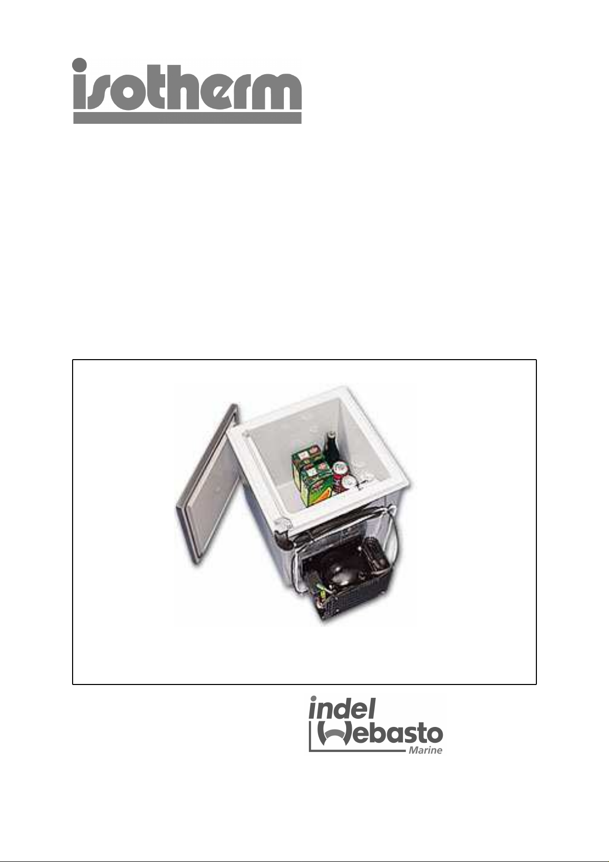
Build-in boxes BI 40
Einbauboxen BI 40
Inbyggnadsboxar BI 40
Indel Webasto Marine S.r.l.
Zona Artigianale
IT-61019 S. Agata Feltria (PU), Italy
Tel: +39 0541 848 030
Fax: +39 0541 848 563
E-mail: info@indelwebastomarine.com
www.indelwebastomarine.com
Page 2

General
Specially designed to operate in tough marine environments, Isotherm fridge boxes are
outstanding in both performance and reliability. Fitted with a fully hermetic, leak-free compressor,
they offer the lowest possible power consumption and noise level. All models are extremely simple
to install. They will operate at a continuous angle-of-heel of up to 30° in all directions, for a short
time even more. To ensure that your Isotherm box operates as efficiently as possible, please follow
these general guidelines:
* Unnecessary opening of the lid will increase power consumption.
* Good ventilation of the compressor and condenser unit will reduce power consumption.
* The electrical system should be in good condition. Inspect batteries and charging levels
regularly. Always use a separate starter battery for the engine. Follow carefully the guide
lines regarding electrical cable areas and fuse placements.
* Keep the inside of the box clean and dry. Keep the lid slightly open to air the fridge box
when leaving the boat for any length of time.
Operation
Temperature setting
The 40L box is fitted with a manually operated, infinitely-variable thermostat. This is turned
clockwise to reduce temperature and anti-clockwise to both increase temperature and activate the
on-off switch at the end position. The switch position has a certain resistance to pass.
The thermostat knob is placed inside the box and allow setting within normal refrigeration
temperatures.
Defrosting
Defrosting shall be made when the frost layer is more than 4 mm thick. Set the thermostat in OFF
position. Store the foodstuff and the bottles as cold as possible during the defrosting. Do not use
sharp metal objects to remove frost or ice. Do not re-start until the box is completely defrosted and
dried.
BI 40 with ASU:
Control panel functions:
The refrigeration unit is switched off when the toggle switch is in the mid position.
“NORMAL-AUTO “ position:
The green light comes on indicating that power is being supplied and the refrigeration program is
activated.
When the engine is running and the power supply (measured at the compressor's control unit) is
more than 13.2 (26.4) volt, the compressor starts supply cooling energy to the holding plate. The
compressor starts within the first 30 seconds and operates at first at low speed with the yellow
indicator “Economy” on. After 30 seconds, the speed of the compressor increases by 75% and the
red “Freeze” indicator lights. This operating condition is maintained until the holding plate is
completely frozen at approximately –14°C (7°F) whic h can take between 30 and 45 minutes,
depending on ambient temperature. On reaching this temperature the compressor stops and red
the light goes out. When the temperature of the holding plate rises to –10°C (14°F) the compressor
re-starts to charge the holding plate and the red light comes on again. This process is repeated a
couple of times every hour to keep the holding plate at its optimum efficiency level. If the engine is
stopped, shortly afterwards the compressor also stops.
When the engine is not running and the battery voltage is below 12.7 (25.4) volt the surplus of
refrigeration energy stored in the holding plate is used first. Only when this has been consumed
does the compressor start and the yellow light comes on indicating that it is now running at its
“Economy” speed to top-up the holding plate. This condition starts when the temperature of the
Page 3

holding plate rises to –1°C (30°F) and stops when i t reaches economy level of –6°C (21°F).
“MAN-TEMP” position:
This position can be used when either shore-power is being used or if for some other
reason a higher or lower refrigerator temperature is desirable. The automatic function is
partially blocked and the temperature is regulated by means of the rheostat, clockwise for
colder and anti-clockwise for warmer. “A” indicates the holding plates temperature point for
“Accumulation”. In this mode the compressor starts but runs at low speed only to keep the
noise level as low as possible.
Indicator lights:
Green: Power and system on, but compressor at still-stand due to
Sufficiently low temperature of the holding plate.
Green + yellow: Compressor running within the higher temperature range.
Green + red: Compressor running on high speed within the lower temperature
range.
Green + yellow + red: Compressor running on lowest possible speed to reach selected
temperature in MAN-TEMP mode.
Flashing yellow + red: Error signal from the black electronic unit. Automatic restart after 1
minute. Select MAN-TEMP if necessary.
Flashing yellow: Low battery voltage sensor has switched off the system. Automatic
re- start occurs when the engine is running and batteries are
charged again.
Note:
After switching on, up to 30 sec. duration is required before the compressor starts. When
the engine is started, a duration of ½ to 10 minutes is required (depending on the boats
charging equipment and battery condition) before the system reacts. When the engine is
stopped, a duration of ½ - 5 minutes (depending on battery condition and level of charge) is
required before the system reacts.
Maintenance
The Isotherm boxes have a fully hermetic closed cooling system and do not require any
maintenance or refilling of refrigerant. The compressor is of domestic type and has a very
high
efficiency and an outstanding life-time. The build-in box shall be left in the boat during the
winter. (If the temperature is below freezing point, the compressor will not start).
The maintenance is reduced to periodically, not less than a year, cleaning of the condenser
from dust. Use a soft brush and no hard objects.
Keep clean inside the box. Use lukewarm water and a mild cleaner for the inside. Put the
lid, during not in operation periods, in a slightly open ventilation position.
Battery voltage sensor
To protect the batteries from becoming completely discharged, a battery voltage sensor
switches off the compressor automatically at the following levels:
System voltage Cut-out Cut-in
12V 10.4V 11.7V
24V 22.8V 24.2V
Page 4
Safety instructions
When connected to shore power, ensure that the power supply is equipped with an automatic
earth leak switch. Danger!
Never tough bare electrical wiring connected to the mains supply. Danger!
Never connect battery charger direct to the refrigeration system. A battery charger must be
connected to the battery
In addition to acid, a newly-charged battery contains explosive gas. Danger!
Never cover up the ventilation systems for the compressor unit.
The refrigeration unit must be disposed by a refrigeration specialist for correct recycling of
components and care taking of the refrigerant.
Fault finding chart
Fault Possible cause Action
Box not cold. Compressor will not start. Check that power is present at
electronic unit.
Check fuse.
Reversed polarity.
Check all connections and cables.
Bridge the thermostat. See wiring
diagram.
If compressor starts this indicates a
faulty thermostat.
If the compressor does not start this
indicates a fault in the electronic unit
Compressor starts but does or the compressor.
Not cool the box. Contact an authorized service agent.
Installation instructions
Mount the box carefully and safe. It is vitally important that the compressor and the condenser
are well ventilated and that cold air can enter and warm air can leave the space around the
compressor unit. (Warm air is leaving upwards).
Do not install the box close to warm areas as the stove, heater or the engine.
Electrical connections
When connecting the box electrically, it is important that following points are considered:
* Always use cables of sufficient area. The area in the following table should be regarded
as a minimum.
Cable area mm² Max cable length in metres, 12 V Max cable length in metres, 24 V
2.5 2.5 5
4 4 8
6 6 12
10 10 20
* Always connect the box directly to the battery or to the battery main switch on the plus
circuit. Do not connect it via the boats own control panel or other diversions as this can
cause a voltage drop in the power supply. Use the included fuse holder with a 15A fuse.
The fuse shall be mounted on the plus cable.
Page 5

* Connect the red cable to the positive (+) terminal and the black to the negative (-)
terminal. Use tab type terminals for the connection to the electronic unit and other cable
connectors of sufficient size for the cable size selected.
* Do not connect the box direct to a battery charger. The battery charger must be connected
to the battery.
Technical data
Type designations: Thermostat: 3040EA2A00000
ASU: 3040EE2A00000
Volume: 40 litres
Voltage: 12/24 Volt
Power consumption: 2.5 - 5 A (12 volt) when compressor is running
Avarage consumption: 0.5 - 0.8 A (12 volt) at 6°C ( 43°F) boxtemp. and 22°C (72°F)
ambient temp.
Compressor: Danfoss BD35F
Refrigerant: R134a (Amount as per label on compressor)
Fuse: 15A/12V, 7.5A/24V
Measurements: Length 560 mm (400 mm without compressor)
Width 400 mm
Weight: 16 kgs
Height 420 mm
Wiring diagram
ASU
Automatic Speed Up
2008-02-26/LLG
BI 40-C eng
Page 6

Allgemeines
ISOTHERM Kühl/Gefrierboxen, speziell entworfen und produziert für die Anwendung im maritimen
Bericht, sind hervorragend in Leistung und Zuverlässigkeit.
Ausgestattet mit einem hermetisch abgeschlossenen Kompressor, bieten sie geringsten
Energieverbrauch und niedrigsten Geräuschpegel.
Alle Modelle sind leicht zu installieren. Sie können bei einem Krängungswinkel bis zu 30 grad
einwandfrei arbeiten, sogar über längere Zeit.
Damit Ihr Isotherm Kühl/Gefrierbox so effektiv wie möglich arbeitet, beachten Sie bitte die folgenden
Richtlinien:
* Unnötiges Öffnen die Box erhöht den Energieverbrauch.
* Eine gute Belüftung von Kompressor und Kondensator senkt den Energieverbrauch.
* Das elektrische System muß in einwandfreiem Zustand sein. Kontrollieren Sie regelmäßig den
Ladezustand der Batterien. Verwenden Sie immer eine separate Starter Batterie für den Motor. Beachten Sie die Vorschriften für das Verlegen elektrischer
Kabel und das Anbringen von Sicherungen.
* Halten Sie den Innenraum stets sauber und trocken.
Wenn Sie das Boot für längere Zeit verlassen, lassen Sie der Deckel leicht
offen, damit die Kühl/Gefrierbox ausgelüftet wird.
Betrieb
Temperatureinstellung
Die Kühlboxen sind mit einem manuellen, stufenlos einstellbaren Thermostat ausgerüstet.
Drehen in Uhrzeigerrichtung reduziert die Temperatur, drehen gegen den Uhrzeigersinn erhöht die
Temperatur und aktiviert den On-Off (Ein-Aus) Schalter.
Temperaturbereich: Normalen Kühlschranktemperatur.
Abtauen
Wenn die Eisschicht dicker als 3-4 mm ist, sollte abgetaut werden. Schalten Sie die Box aus. Lagern Sie
die Lebensmittel Während der Abtauphase so kalt wie möglich. Verwenden Sie keine scharfkantigen
Gegenstände, um das Eis zu entfernen. Schalten Sie die Kühlbox erst wieder ein, wenn er vollständig
abgetaut und getrocknet ist.
Box mit ASU
Bei mittlerer Schaltposition ist die Anlage ausgeschaltet.
Das Isotherm ASU Kühlsystem kann auf zwei Arten betrieben werden.
Schalter auf NORMAL-AUTO Position – die optimale Kühltemperatur wird automatisch eingehalten bei
absolut niedrigstem Batterieverbrauch.
MAN-TEMP Position – die automatische Funktion ist teilweise blockiert, die Kühltemperatur kann
manuell eingestellt werden.
NORMAL-AUTO Position:
Das grüne Licht leuchtet auf und zeigt an, daß Strom fließt und das Kühlprogramm aktiviert wurde.
Wenn der Motor läuft und die Spannungszufuhr (gemessen an der Steuereinheit am Kompressor) über
13,2 (26,4) Volt liegt, beginnt der Kompressor, Kühlenergie an den Kältespeicher zu liefern. Der
Kompressor startet innerhalb der ersten 30 Sekunden und arbeitet zuerst bei niedrigen Drehzahlen, die
gelbe Anzeige leuchtet auf „Economy”. Nach 30 Sekunden erhöht sich die Drehzahl von Kompressor
um 75%, das rote Licht leuchtet auf -„Freeze“. Diese Betriebszustand wird aufrecht gehalten, bis die
Freezer-Einheit vollständig gefroren ist bei ca. –14°C. Das kann zwischen 30 und 45 Minuten dauern.
Wenn die Freeze-Temperatur erricht ist, stoppt der Kompressor und das rote Licht geht aus.
Steigt die Temperatur des Kältespeichers auf -10°C, startet der Kompressor und das rote Licht geht
wieder an. Diese Vorgang wiederholt sich mehrere Male pro Stunde, damit der Kältespeicher immer auf
optimalen Kühlniveau ist.
Wird der Motor gestoppt, geht kurz darauf auch der Kompressor aus.
Wenn der Motor nicht läuft und die Batteriespannung unter 12,7 (25,4) Volt liegt, wird zuerst die im
Kältespeicher vorhandene, überschüssige Kühlenergie verbraucht. Erst wenn diese konsumiert
startet der Kompressor und das gelbe Licht geht an, was bedeutet, daß er nun auf „Economy“- stufe
läuft. Diese Vorgang beginnt, wenn die Temperatur des Kältespeichers auf -1°C gestiegen ist und endet,
wenn die „Economy“ – Stufe bei –6°C erreicht ist.
wurde,
Page 7

Kältespeicher vorhandene, überschüssige Kühlenergie verbraucht. Erst wenn diese konsumiert wurde,
startet der Kompressor und das gelbe Licht geht an, was bedeutet, daß er nun auf „Economy“- stufe
läuft. Diese Vorgang beginnt, wenn die Temperatur des Kältespeichers auf -1°C gestiegen ist und endet,
wenn die „Economy“ – Stufe bei –6°C erreicht ist.
MAN-TEMP Position
Diese Einstellung kann verwendet werden, wenn Landstrom benutzt wird oder wenn aus irgendeinen
anderen Grund eine höhere oder niedriger Kühltemperatur gewünscht wird.
Die Automatikfunktion ist dann teilweise blockiert und die Temperatur wird mit Hilfe des
Regelwiderstands eingestellt: im Uhrzeigsinn = wärmer, entgegen der Uhrzeigerrichtung = wärmer. „A“
steht für „Akkumulationstemperatur“ des Kältespeichers.
In dieser MAN-TEMP Einstellung startet der Kompressor und läuft bei niedrieger Drehzahl.
Bei gestopptem Motor (da Landstrom) wird dadurch der Geräuschpegel von Kompressor und Lüfter
extrem gesenkt, was als sehr angenehm empfunden wird.
Leuchtanzeigen
Grün: Strom liegt an, System ist an, aber Kompressor steht noch still, da die
Temperatur des Kältespeichers noch niedrig genug ist.
Grün + gelb: Kompressor läuft bei niedriger Drehzahl, um die Kältespeicher kühl zu
halten, ohne ihn „aufzuladen“.
Grün + rot: Kompressor läuft bei Maximaldrehzahl, um den Kältespeicher zu laden.
Grün + gelb + rot: Kompressor läuft bei niedriger Drehzahl im MAN-TEMP Modus.
Gelb + rot blinkt: Fehlersignal von Steuereinheit. Automatischer Neustart nach 1 Minute.
Gelb blinkt: Die Batteriespannung ist zu niedrig, der Sensor hat das System
abgeschaltet. Es erfolgt ein automatisches Neustarten, wenn der Motor
läuft, um die Batterien wieder aufzuladen.
Hinweis
Nach dem Einschalten dauert es ca. 5 – 30 Sekunden, bevor das System startet. Wenn der
Motor an ist, dauert es ½ bis 10 Minuten, bevor das System reagiert (abhängig von
Ladeausrüstung und Batteriezustand). Wird der Motor gestoppt, dauert es ½ bis 5 Minuten,
bevor das System Reaktion zeigt.
Wartung
Die Isotherm Kühlboxen besitzen ein hermetisch abgeschlossenes Kühlsystem und benötigen deshalb
keine Wartung, Kühlmittel muß nicht nachgefüllt werden. Der Kompressor ist sehr zuverlässig und
Leistungsstark und besitzt eine lange Lebensdauer. Über Winter sollte die Kühl/Gefrierbox im Boot
verbleiben. (Wenn die Temperatur unter 0 Grad C sinken, geht die Anlage nicht an).
Die Wartung beschränkt sich auf das Reinigen des Kondensators einmal pro Jahr. Verwenden
Sie dazu eine weiche Bürste. Halten Sie den Kühlboxinnenraum sauber. Nehmen Sie lauwarmes
Wasser und ein mildes Reinigungsmittel, um ihn zu saubern.
Halten sie der Deckel einen Spalt offen, wenn die Kühl/Gefrierbox nicht in Betrieb ist, damit sie auslüften
kann.
Batteriespannungssensor
Damit die Batterien nie ganz leer werden, schaltet ein Spannungssensor den Kompressor automatisch
ab bei folgenden Werten:
Systemspannung Ausschalten Einschalten
12 Volt / 24 Volt 10,4 Volt / 22,8 Volt 11,7 Volt / 24,2 Volt
Sicherheitshinweise
Wenn Sie Landstrom Anschließen, achten Sie darauf, daß die Stromzufuhr mit einer Sicherung über
einen F1-schalter abgesichert wird. Gefahr!
Berühren Sie niemals offene Wechselstromkabeln. Gefahr!
Schließen Sie nie ein Batterieladegerät direkt am Kühlschranksystem an.
Batterieladegeräte müssen an die Batterien angeschlossen werden!
Page 8

Beachten Sie, daß Batterien Säure enthalten.
Decken Sie die Belüftung der Kompressoreinheit niemals ab.
Eine spätere Verschrottung des Aggregates darf nur von Fachmann vorgenommen werden, der die
enthaltenen Bestandteile der Wiederverwertung zuführt und das Kühlmittel korrekt entsorgt.
Fehlersuche-Checkliste
Fehler Möglische Ursache Maßnahmen
Kühlbox wird nicht kalt
Kompressor startet, aber
erfolgt keine Kühlung.
Kompressor startet nicht.
Überprüfen Sie, ob Strom fließt am Anschluß.
Kontrollieren Sie Polarität und Sicherung.
Prüfen Sie alle Anschlüße und Kabel.
Überbrücken Sie am Thermostat
Kabelanschlüsse.
Wenn der Kompressor startet, deutet dies auf
einen Defekt im Thermostat.
Wenn der Kompressor nicht startet, liegt ein
Fehler in der Elektronik oder am Kompressor vor.
Kontaktieren Sie Ihre Werkstatt.
Kontaktieren Sie Ihren Händler bzw. Ihre
zuständige Werkstatt.
Installationsanleitung
Die Box muss gut befestigt werden.
Es ist von größter Wichtigkeit, daß Kompressor und Kondensator gut belüftet werden und daß kalte Luft
am Boden einströmen und Warme oben entweichen kann.
Der Kompressor sollte senkrecht im Boot stehen, er arbeitet aber bei einem Krängungswinkel bis zu 30
Grad über einen gewissen Zeitraum einwandfrei.
Elektrische Anschlüsse
Wenn Sie die Kühl/Gefrierbox anschließen, müssen Sie folgendes beachten:
* Verwenden Sie immer die richtige Kabelgröße (korrekten Kabelquerschnitt).
Folgende Maße werden als Minimum verlangt:
Kabelquerschnitt in mm² Maximale Kabellänge in m
12 Volt 24 Volt
2,5 2,5 5
4 4 8
6 6 12
10 10 20
* Schließen Sie die Kühl/Gefrierbox immer direkt an der Batterie oder am Batteriehauptschalter,
positiver Stromkreis, an. Schließen Sie nicht über das Schaltbrett des Bootes oder andere
Umwege an, dies kann zu Spannungsabfall führen.
Verwenden Sie die beigefügte Sicherungsfassung mit 15A Sicherung.
Wird ein Schalter installiert, muss dieser auch für mind. 15 A ausgelegt sein.
* Schließen Sie das rote Kabel am positiven (+) und das schwarze Kabel am
negativen (-) Anschluß an. Verwenden Sie der Kabelgröße entsprechende
Kabelanschlüsse.
* Schließen Sie die Kühlbox niemals direkt am Batterieladegerät an. Der Batterielader muß an der
Batterie angeschlossen werden.
Page 9

Technische Daten
Typ: 3040EA2A00000 Thermostatmodell
3040EE2A00000 ASU Modell
Spannung: 12/24 Volt
Stromverbrauch: 2,5 - 5A in Betrieb (12 V)
Mittlerer Stromverbrauch: 0,5 - 0,8 A/h. (12 V) bei Temperatur in der Box +6°C, Umgebung +22°C.
Kompressor: Danfoss BD35F
Kältemittel: R134a (Füllmenge gemäß Schild am Kompressor).
Sicherung: 15 A Auto Flachsicherung
Abmessungen: Länge 565 mm (400 mm ohne Kompressor)
Breite 400 mm
Höhe 420 mm
Gewicht: 16 Kg
Elektrische Anschlüße
2008-02-26/LLG
BI 40-C ty
ASU
Automatic Speed Up
Page 10

Allmänt
Isotherm kylboxar är helt konstruerade efter de höga krav som ställs i marin miljö, både vad
gäller prestanda och utförande. De har en modern hermetisk helt läckagefri kompressor
som ger såväl lägsta strömförbrukning som i det närmaste ljudlös gång.
Kylboxarna är enkla att bygga in och installera. De tål en lutning på upp till 30º, tillfälligt mer.
Köldmediet är freonfritt, R 134a.
För bästa funktion är det viktigt att följande punkter beaktas:
* Undvik onödigt "spring" i kylboxen. Det höjer strömförbrukningen.
* God ventilation av kompressor och kondensor har också stor inverkan på
strömförbrukningen. Placera boxen där bra luftväxling finns till hands.
* Ett väl fungerande elsystem är en förutsättning. Se över batterier och laddning
regelbundet. Ha alltid ett separat startbatteri för motorn. Följ anvisningarna vad
gäller kabelarea och säkringsplacering.
•
Håll rent och torrt i boxen. Torka ur eventuellt kondensvatten som samlats i botten.
•
Ställ alltid upp locket i vädringsläge när Du lämnar båten ock kylboxen är avstängd.
Bruksanvisning
Temperaturreglering
Med kylboxens termostat kan man steglöst reglera temperaturen enligt följande:
vrids termostaten medurs blir det kallare och vrids den moturs blir det varmare
i boxen. Termostaten har en strömställare i sitt ändläge moturs, med vilken boxen
kan stängas av och sättas på, et distingt fjädermotstånd överbryggas när knappen vrides till avstängt läge.
Termostaten tillåter reglering av temperaturen inom normal kylskåps/kylbox temperatur.
Avfrostning
Avfrostning skall ske då en tjock (över 4 - 5mm) frostbeläggning finns på förångaren.
Stäng av boxen på termostatvredet. Förvara de matvaror och drycker som fanns i boxen så kallt
som möjligt t.ex. frysväskor el. dyl. under tiden avfrostningen äger rum. Använd inga vassa föremål för att avlägsna isen.
Starta ej boxen igen förrän det är fullständigt avfrostat och urtorkat.
Box med ASU
Manöverpanelens funktioner:
Aggregatet är avstängt med panelens strömställare i mittläge.
Läge “NORMAL-AUTO”:
Gröna lampan tänds omgående och visar att ström är tillkopplad och följande program kopplas
in:
- Då motorn går och spänningen i elsystemet, mätt vid kylkompressorns elektronikdel, är över
13,2 volt (26,4 volt) startar kompressorn och arbetar för att frysa ner och ladda kylmagasinet. Kompressorn startar inom 30 sek. och går den första halvminuten på lågt varvtal och
gul lampa "Economy” tänd. Efter 30 sek. varvar kompressorn upp 75% och röd lampa
“Freeze” tänds. Så kommer kompressorn att arbeta ända tills kylmagasinet är fulladdat vid
ca. –14°C, vilket tar mellan 30 – 45 min. Därefter stannar kylkompressorn, röd lampa slocknar och kompressorn återstartar vid ca. –10°C, någon gång i timmen för att hålla kylmagasinet fulladdat. Om båtmotorn stängs av, stannar också kompressorn.
- Då båtmotorn ej går och spänningen är lägre 12,7 volt (25,4 volt) används alltid i första hand
den lagrade kylan i kylmagasinet. Först när den är förbrukad kopplas kompressorn in och går
då på lågt varvtal med gula lampan “Economy” tänd, för att underhållskyla. Kompressorn
Page 11

startar då kylmagasinet är varmare än –1°C och stannar då kylmagasinet nått –6°C,
alltså innan kylmagasinet laddas.
Läge “MAN-TEMP”:
- Detta läge kan användas när man ligger på landström eller av annan anledning vill
åstadkomma kallare eller varmare temperatur i boxen. Automatiken är då urkopplad och
temperaturen regleras manuellt med reostaten på manöverpanelen. Medurs = kallare
och moturs = varmare. Vid “A” passeras kylmagasinets temperatur för “Ackumulering”.
Då kompressorn startar i MAN-TEMP går den företrädesvis på lågfart för att hålla ljudnivån så låg som möjligt. Om temperaturskillnaden mellan inställd och verklig då kompressorn startar, går den dock ett tag på högre varvtal för att snabbare kyla ner och jämna ut temperaturskillnaden.
Signaler:
Fast grön lampa: Aggregatet tillkopplat, får ström, kompressorn går ej.
Fast grön + gul: Kompressorn går på lågvarv inom det höga temperaturområdet.
Fast grön + röd: Kompressorn går på högvarv inom det låga temperaturområdet.
Fast grön + gul + röd: Kompressorn går på lägsta möjliga varvtal för att uppnå inställd tem-
peratur.
Blinkande gul + röd: Felsignal från elektroniken. Automatisk återstart inom 1 min.
Ställ strömställaren läge MAN-TEMP.
Blinkande gul: Batterivakten har löst ut och stängt av aggregatet. Starta motorn för
laddning och kompressorn återstartar automatiskt.
Obs! Då strömställaren slås till dröjer det ca. 30 sek. innan kompressorn startar. Då
båtmotorn startats dröjer det ½ - 10 min innan aggregatet reagerar, beroende på båtens
laddningsutrustning och batterikondition. Då båtmotorn slås av dröjer det ½ - 5 min innan
aggregatet reagerar, beroende på batteriernas kapacitet och laddningstillstånd.
Underhåll
Isotherm kylboxar har ett helt hermetiskt slutet kylsystem med lödda ledningar och
förslutningar och behöver inget underhåll och behöver ej påfyllning av köldmedium. Kompressorn är av hushållstyp och har förutom mycket hög verkningsgrad en
i särklass lång livslängd.
Kylboxen skall sitta kvar i båten under vintern (men förmår dock inte alltid starta vid
minusgrader). Underhållet inskränker sig till att regelbundet och vid behov göra rent
kompressorns kondensorgaller från damm med en pensel e.d.
Håll kylboxen ren invändigt, speciellt viktigt på hösten då boxen tömmes och stängs av.
Ställ luckan i vädringsläge under vintern.
Batterivakt
För att skydda batterierna mot urladdning slår en batterivakt ifrån kompressorn vid
för låg spänning enligt följande:
Systemspänning frånslag tillslag
12 volt 10,4 volt 11,7 volt
24 volt 22,8 volt 24,2 volt
Page 12

Säkerhetsföreskrifter
-Vid anslutning till landström måste strömförsörjningen vara jordad och ansluten till
jordfelsbrytare, annars föreligger stor risk för personskada. Kan medfara livsfara!
- Ingrepp i köldmediekretsen får absolut ej göras.
- Köldmedium får ej släppas ut i luften.
- Se till att boxens ventilationssystem ej blockeras.
- Anslut ej batteriladdare direkt till kylboxen. Batteriladdare måste kopplas till batteriet.
Felsökningsschema
Felindikering Möjlig orsak Åtgärd
Boxen blir ej kall. Kompressorn startar ej. Kontrollera att ström
finns fram till elboxen.
Kompressorn startar Kontrollera säkringen.
men ger ingen kyla. Kontrollera att plus och
minus ej förväxlats, el
kablar och kabelanslutningar.
Överbrygga termostaten, startar
kompressorn då, är termostaten
felaktig.
Om åtgärderna i övrigt inte av
hjälper felet, kontakta auktori
serad serviceverkstad.
Kontakta auktoriserad service
verkstad.
Installationsanvisning
Boxen skall sättas fast ordentligt i det utrymme som valts för montering.
Det är viktigt att god ventilation finns i utrymmet där boxen/kompressorn är monterad. Man
skall därför se till att kall luft kan tillföras undertill för att sedan släppas ut uppåt. (Varm luft
stiger uppåt). Installera ej boxen nära värmekällor såsom spis, värmare, motorn eller dyl.
Kompressorn skall i sitt normalläge sitta rakt/vågrätt i båten. Den klarar lutningar på 30°,
tillfälligt mer.
Elanslutning
Vid inkoppling till båtens elsystem är det mycket viktigt att hänsyn tas till följande punkter:
Använd väl tilltagen kabelarea, se tabellen.
Kabelarea mm² Max. kabellängd (m) vid 12V Max. kabellängd (m) vid 24V
2,5 2,5 5
4 4 8
6 6 12
10 10 20
Page 13

Tekniska data
Typbeteckning: 1381G Termostatstyrd
1383G ASU
Volym: 40 liter
Spänning: 12/24 volt
Strömförbrukning: ca. 2,5 - 5A i drift (12 volt)
Medelströmförbrukning: 0,5-0,8 A/tim (12 volt) vid 6°C i boxen och 22°C omgivningstemperatur.
Kompressor: Danfoss BD35F
Köldmedium: R134a (Fyllnadsmängd enligt dekal på kompressorn).
Säkring: 12V/15A alt. 24V/7,5A
Mått: Längd 560 mm (400 mm utan kompressor)
Bredd 400 mm
Höjd 420 mm
Vikt: 16 kg
Elinkoppling
ASU
Automatic Speed Up
2008-02-26/LLG
BI 40-C
Thermoprodukter AB
Dragonvägen 6
SE-392 39 Kalmar, Sweden
Tel: +46 480 425 880
Fax: +46 480 127 75
E-mail: info@isotherm.com
www.isotherm.se
 Loading...