

Page 1

Installation and operating instructions
Page 2

Table of Contents
1 Preface
2 Installation
2.1 Unpacking and Inspection
2.2 Safety Considerations
2.3 Tools and Materials Required
2.4 Getting Good Results
2.5 Plan Ahead
2.6 Location and Ventilation
2.7 General Electrical Installation
2.8 Shore Power
2.9 Electronic Unit
2.10 Locating and Installing the Compressor/Condenser Unit
2.11 Locating and Installing the Evaporator
2.12 Thermostat Control Box
2.13 Quick-Couplings
3 Maintenance
4 Operation
4.1 Start Up
4.2 Protection System
5 Troubleshooting Guide
Appendix A Building or Modifying an Icebox for Use with an Isotherm Refrig-
6
eration System
7 Appendix B Bending a Flat Evaporator
INSTALLATION AND OPERATING INSTRUCTIONS
PRODUCED BY
GREAT WATER, INC.
BRUNSWICK MAINE
WWW.GREAT-WATER.COM
207 729 8500 TEL 517 813 6509 FAX
INFO@GREAT-WATER.COM
Page 3

1 Preface
Isotherm Classic Compact refrigeration systems are designed and built to provide excellent performance and many years of trouble-free service. The system is pre-charged with environmentally
safe R-134a refrigerant and can be owner installed. This manual has been prepared to provide information needed for proper installation, operation and maintenance. Before beginning installation please read it carefully.
2 Installation
2.1 Unpacking and Inspection
Please examine the box and contents for signs of shipping damage. If there is any damage, contact the carrier immediately. All units are shipped with insurance but the carrier must be notified
immediately of any shipping damage in order to process a claim.
Each system consists of:
1. Compressor/condenser unit.
2. Click on mounting bracket.
3. Evaporator with 6 feet of flexible tubing.
4. Thermostat with control wiring.
5. Owners manual and warranty registration card.
2.2 Safety Considerations
Whenever working on the electrical system make certain that all circuits are off before opening
any electrical panels. Disconnect shore power cables and turn battery switches off. Follow ABYC
standards for electrical installations. If in doubt contact a certified technician.
2.3 Tools and Materials Required
• Electric drill and bits for pilot holes to attach compressor mounting bracket and evapora-
tor.
• Wire cutters and electrical terminal crimping tool.
• Good quality electrical wire of suitable gauge (usually 10/2).
• Screwdrivers.
• Wrenches.
2.4 Getting Good Results
Classic Compact refrigeration systems are designed for use in a marine environment and will operate efficiently for many years with a minimum of maintenance when installed properly. Plan the
installation carefully and choose a suitable location for the refrigerator. The insulation and construction of the refrigerator box are very important and will have a dramatic effect on the performance and power consumption of the refrigerator system.
A box with thicker insulation will require less power to maintain the proper temperature. Three to
four inches of a good quality insulation material with a value of R-5 per inch is recommended.
This will result in a box with an overall insulation value of R-15 to R-20.
The box must be well sealed. Lids must be airtight. Drains (if fitted) must be closed tightly.
Often boxes are pre installed by the manufacturer and modifications are not always easy to make.
If you are planning to build or modify a box please see Appendix A: “Building or Modifying an Icebox for Use with an Isotherm Refrigeration System.”
Page 4
Battery capacity should be at least 75 Ah to enable sufficient power to be stored during engine
F
D
C
P
T
101N0200
operation.
All the electrical power supply equipment such as alternator, regulator, cables, connectors and
batteries must be kept in good condition.
2.5 Plan Ahead
· Plan tubing and wire runs carefully before starting.
· Avoid getting dirt or moisture on coupling ends. Leave dust caps on until ready to connect.
· Provide sufficient air circulation for air-cooled condenser.
· Use a dedicated 15 amp circuit breaker.
2.6 Location and Ventilation
All refrigerators are heat-transfer machines. They
transfer the heat from the inside of the box to the
outside. If adequate ventilation is provided, the
compressor will operate more efficiently and use
F
less power.
Inlet vent should be located at the bottom (as low
D
C
P
T
101N0200
as possible) and the outlet vent at the top of the
refrigerator (as high as possible); this supports the
natural flow of convection of heat from cool
Fig. 1
(bottom) to warm (top).
A vent of 20 to 30 square inches is recommended at
top and bottom (fig. 1).
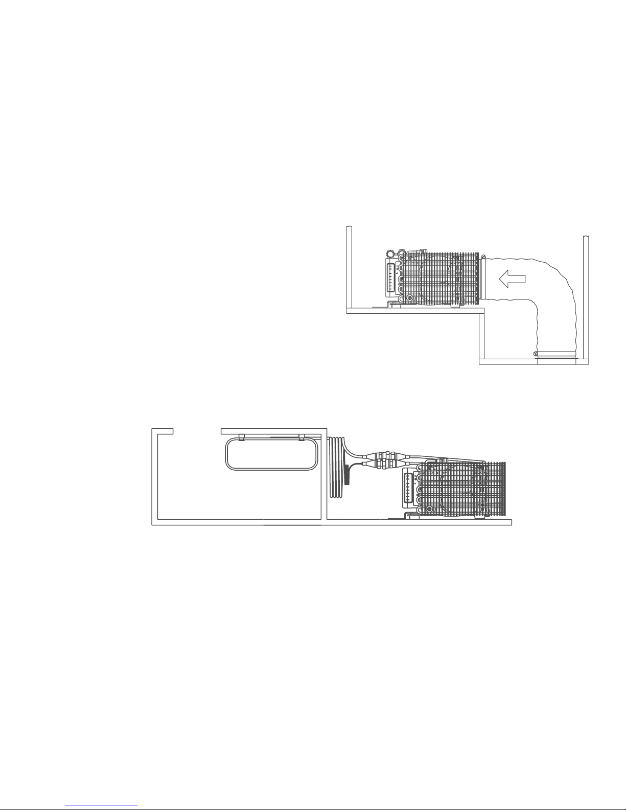
Make sure there is sufficient space around the compressor to connect and tighten the quickconnect couplings on the pipes (fig. 2).
Fig. 2
2.7 General Electrical Installation
Good performance and efficient operation of the refrigeration system depends on a good electrical installation that will deliver power to the system with a minimum of voltage loss. If the boat's
electrical panel cannot deliver the required power with no more than one half volt of loss the circuit may need to be connected directly to the boat’s main battery switch with the fuse supplied.
In either case the circuit that supplies the power to the refrigerator must be protected with either
a 15 Amp fuse or circuit breaker. Always use a separate dedicated circuit to power the refrigeration system. Remember that the negative connection is equally important in delivering power to
the unit.
Use a good quality marine duplex wire to make the connection between the unit and the power
source. Tinned cable is recommended because it will give better resistance to corrosion and long
service life.
Keep the length of the run as short as possible (less than 6 feet).
For runs up to 10 feet use 12 gauge wire (12/2 duplex).
For runs up to 30 feet use 10 gauge wire (10/2 duplex).
Make sure the circuit is not connected to the power source while making these connections.
Page 5

2.8 Shore Power
Battery Charger
Battery
Electronic Unit
When shore power is available the
electrical requirements of the refrigeration system can be supplied
by a regulated battery charger of
at least 5 amps capacity. This
battery charger must be connected to the battery and never
directly to the electronic unit (fig.
3).
2.9 Electronic Unit
The electronic unit must always be connected directly
to either the battery or the main switch (plus to plus –
minus to minus).
It is very important that cables of correct dimensions
are used for the power supply.
2.10 Locating and Installing the Compressor/
Condenser Unit
The compressor/condenser unit is air-cooled and must
be mounted in a well-ventilated location. The efficiency of the system will be greatly reduced if the
temperature of the cooling air rises above 95°F. Ideally the air supply should be drawn from a cool area
such as the bilge and the warmed exhaust air vented
out of the space. Avoid warm locations such as an engine room or closed spaces where the warm air will recirculate over the condenser. Make sure the ventilation to the space will not be restricted when the space
is packed for cruising.
The compressor/condenser must be located within 6
feet of the evaporator so that the refrigeration tubing
will reach.
The click–on bracket simplifies mounting the compressor. The bracket can be mounted on a bulkhead or on a
shelf. The compressor can be easily snapped onto the
bracket after it is screwed into position (fig. 4).
The compressor/condenser must be mounted in a horizontal position and will operate at a heeling angle up
to 30° (fig. 5).
The compressor/condenser is nearly silent in operation
so it can be mounted near sleeping cabins or even under a berth.
The compressor must be mounted in a dry location to
protect the electrical components.
Fig. 3
Fig. 4
Fig. 5
Page 6

2.11 Locating and Installing the Evaporator
The evaporator can be mounted horizontally or vertically on a sidewall near the top of the box, accessible from the box opening. In positioning the
evaporator consider the routing of the refrigerant
lines out of the box.
Mark the location of the mounting holes, drill and
attach the evaporator with the screws and the plastic standoff spacers provided. Do not use screws
longer than those provided, as they will penetrate
the insulation (fig. 6).
Note: It ma y be easie r if the t hermo stat’s se nsor i s
attached before final mounting of the evaporator.
When the evaporator mounting holes are completed, locate the hole for the refrigerant lines.
Use a 1 1/2 " diameter hole saw to make a passage
way through the box for the copper tubing. In locating the hole, consider the routing of the tubing,
both inside and outside the box. Avoid sharp bends
that will make it difficult to run the tubing to the
compressor/condensing unit. The aluminum tube
may be bent to a minimum of 1½" radius by hand.
Repeated bending should be avoided (fig. 7).
Note: It is possible to reshape an O-evaporator.
Remove the rivets holding it together and carefully
form it to the required shape required (fig. 8).
Flat evaporators can be bent, using a special bending tool. (See Appendix B.)
Fig. 6
Fig. 7
Fig. 8
Page 7

2.12 Thermostat Control Box
The thermostat control box can
be installed either inside or outside the refrigerator. When locating the thermostat make sure
it is in a dry area and will not be
subjected to damage. Check that
the thin capillary sensor tube is
long enough so that it may be attached to the evaporator, either
with a clip or with a special
screw on clamp (fig. 9). Uncoil
the required length of capillary
tubing and secure the excess in a
coil. Avoid bending or twisting
the capillary tube repeatedly to
prevent kinking or cracking the
tube. Connect the thermostat
wiring to the electronic unit connections “T” and “C” (fig. 10).
The polarity of these connections
is not important. On some models, the speed of the Danfoss
compressor is set with a resistor
that is part of a three inch
jumper that is connected to the
"C" terminal. Leave this wire in
place. Connect the free end of
this short wire to one of the thermostat wires.
After mounting the thermostat
housing, turn the control knob
completely counterclockwise to
the off position.
Fuse/
Circuit Breaker
Thermostat
Sensor Tube
Fig. 10
Fig. 9
F
D
C
P
T
Speed Setting Resistor
(on some models)
2.13 Quick-Couplings
The evaporator is supplied with 6 feet of pre-charged tubing with a pair of self-sealing quick connect couplings. The compressor/condensing unit has a mating pair of these fittings. Connecting
the quick-connect couplings together completes the refrigeration circuit without the loss of any
refrigerant.
All quick connect couplings must be kept free of dirt and moisture. Any contamination can
cause failures.
Save the caps in the event the system needs to be removed for service.
A suggestion: screw the caps together, place them in a small plastic bag and tape them to the
tubing near the fittings so they will be available if needed.
Page 8

Thread the couplings together by hand until you are sure the couplings are properly mated.
Tighten the couplings by turning the swivel nut on the female fitting while holding the male fitting
stationary.
It is important not to twist the tubing when
tightening the fittings. If the male fitting is
allowed to rotate the tubing may break
causing serious damage to the system.
Continue tightening the female fitting until
positive resistance is felt. Screw the couplings to the bottom of their threads and ,
tighten finally firmly using 21 and 24mm
wrenches (fig. 11). Tighten the female cou-
Fig. 11
pling another 1/6 to 1/4 rotation to insure a
leak-proof joint.
After the installation is complete and the system has been tested the 1½ inch hole in the box
must be filled and sealed with a polyurethane foam sealant.
3 Maintenance
Maintenance is not normally required and the refrigeration unit may remain in the boat during the
winter. To maintain efficiency, remove any dust that may have collected on the condenser tubes
every few years.
It is time to defrost when frost builds up to 1/4 inch.
4 Operation
4.1 Start Up
Make sure the circuit supplying the refrigerator is turned on. The compressor should start within
30 seconds and a low humming noise will be heard. The fan will start after a short delay. In a
few minutes the evaporator will begin to frost. The thermostat is adjustable and has an on/off
switch. Turning the control knob to the extreme counter clockwise position turns the unit
off. Turning the control to the right (clockwise) will turn the unit on. Turning the control clockwise lowers the temperature setting with the lowest temperature at the extreme clockwise position.
A good initial setting is mid-range. Positions “4” – “7” are recommended for making ice cubes.
4.2 Protection System
The compressor is equipped with an electronic protection system. The system is activated when
the compressor is overloaded and fails to start for any reason. It is also activated if the batteries
are under- or overcharged.
To prevent battery damage the protection system will shut off the compressor when the input
voltage at the electronic module falls below 10.3 volts. The compressor will not start again until
the input voltage rises to 11.5 volts.
Page 9

5 Troubleshooting Guide
Problem Possible Cause Action
Refrigerator isn’t cold. Compressor won't start.
Compressor starts but
doesn't cool refrigerator.
Compressor runs all the time. Air leak. Check gasket/seal of door. Make sure door
Condensor dirty. Clean condensor with soap, water, and a brush.
Insufficient ventilation.
System charge of refrigerant R-134a may be low.
Check that power is present at terminal box.
Check fuse. Check all connections and cables.
Check the thermostat connections. If the compressor still doesn't start this indicates a fault in
the electronic unit or compressor. Contact an
authorized service agent.*
Contact an authorized service agent.*
closes properly.
Improve ventilation. Refer to installation instructions.
Contact an authorized service agent.*
Refrigerator too cold inside. Faulty thermostat Turn thermostat to "off" position and make sure
unit turns off. Adjust to minimum setting and
check that sensing tube is properly attached to
evaporator.
* If a complicated fault does occur, such as those requiring specialist assistance, please contact Great Water, Inc. or your local marine distributor for advice. Great Water can be reached at: Phone: (814) 838-0786
Fax: (814) 838-8700 email: info@great-water.com.
6 Appendix A
Building or Modifying an Icebox for Use with an Isotherm Refrigeration System
Page 10

7 Appendix B Bending a Flat Evaporator
The following instructions should be used when bending a flat evaporator to install in a refrigerator or freezer box.
The evaporator should be bent to cover as many sides of the box as possible, with a minimum of
two sides for a refrigerator and three sides for a freezer. The evaporator should be placed as high
in the box as possible. Use the enclosed bending tool.
• Plan exactly where the evaporator should be located. Begin by selecting a position in the
box wall where a hole can be made through which the connection tube can be passed. The
hole should have a diameter of at least 1.25" (33 mm) to allow the quick couplings to pass
through. It is very important that the short length of tubing clamped to the outside of the
evaporator be protected. Be sure to leave enough space for this tubing inside the box because it must never be stressed or pulled through the clamp to alter its length.
• Begin measuring the interior of the box from the point where the edge of the evaporator
will be located. The first measurement should be for the end of the evaporator with ample
space to accommodate the tubing.
• Continue measuring around the inside corners of the box. Write down these measure-
ments.
• Calculate where the evaporator must be bent to fit into the box. It is important to account
for the extra length of evaporator needed to round the corners of the box. A 90-degree
bend requires 1.25" (33 mm) length of evaporator when the inner radius is .75" (20mm).
Remember also that the evaporator should be mounted .5" (13 mm) from the box wall using
the plastic stand-offs provided. These factors will affect your calculations. Refer to next
page for an example of how to calculate location of bends.
• Put a piece of plywood down on a workbench with an open space underneath so that there
will be room to accommodate the evaporator as you bend it.
• Mount the bending tool on the edge of the plywood for the evaporator to be screwed to in
order to keep it stationary while bending.
• Draw a line down the length of the bending tool to mark the center. This corresponds to
where the marks you have made on the evaporator for the start of each bend will line up.
• Begin bending the end of the evaporator farthest away from the end where the tubing is
coiled.
• Mark the location of the mounting holes, drill and attach the evaporator with the screws
and the plastic standoff spacers provided. Do not use screws longer than those provided as
they will penetrate the insulation.
• Install the evaporator in the box after it has been bent. If necessary, the evaporator can
be carefully bent further to fit through the opening and then bent back to 90˚ inside the
box.
Page 11

a = 0"
c = 12"
b = 10.75"
d = 28.25"
e = 29.5"
f = 40"
= 10.75"
Take length of first side (AB) 12.0"
Subtract width of first bend - 0.75"
add length of radius of bend + 1.25"
Subtract width of first stand-off - 0.5"
location of beginning of first bend is 10.75"
location of the end of the first bend is 12.0"
Calculate location of first bend:
C
e
d
= 28.25"
Subtract width of 2 stand-offs - 1.0"
Add length of second side (BC) + 18.0"
Subtract length of second bend - 0.75"
add length of radius of second bend + 1.25"
location of beginning of second bend is 28.25"
location of the end of the second bend is 29.5"
Calculate location of second bend:
D
f
drawings are not to scale
AB = 12"
The following example illustrates how to calculate
where the bends should be made in an evaporator.
Measure interior of box from the point where the
edge of the evaporator will be located. In this
example, the evaporator will cover three sides of the
box. The lengths of the box wall the evaporator will
cover are:
BC = 18"
CD = 12"
c
b
a
B
A
Page 12

Isotherm Classic Compact Technical Data
Model Max Box
Size
Cu. Ft.
2009 4.4 2.5 10.6 6.3 6.1 9.4 8.3 3.3 Small “O” 24 BD35F none
2309 5.3 4 10.6 6.3 6.1 12.6 9.1 3.9 Medium “O” 24 BD35F Black 698 Ohm
2503 7.1 6 10.6 6.3 6.1 15.0 11.0 5.5 Large “O” 24 BD50F Black 698 Ohm
2007 3.5 2.5 10.6 6.3 6.1 9.8 13.8 4.3 Small “L” 24 BD35F none
2010 4.4 4 10.6 6.3 6.1 15.7 8.3 6.7 Large “L” 24 BD35F Red 1.50 KO
2005 2.1 2.5 10.6 6.3 6.1 13.8 5.1 0.5 Small Flat 24 BD35F none
2013 14.1 6.5 10.6 6.3 6.1 55.0 12.0 0.5 V. Large Flat 24 BD50F Red 1.50 KO
2017 4.4 5 10.6 6.3 6.1 39.4 10.6 0.5 Large Flat 24 BD50F Red 1.50 KO
Dimensions in inches
Max
Current
Amps
Dimensions of
Compressor
L W H L W H
Dimensions of
Evaporator
Voltage
Fuse
12/24 volt
15 A Car type blade fuse.
Evaporator
Style
Weight
lbs
Danfoss
Compressor
Model
Resistor
Radiosuppression
Battery protection
Fulfills EMC directives CE-marked
Power cut-off at 10.4 (22.8) volt.
Re-start at 12 (24) volt.
 Loading...