

Page 1

CRYO CALIBRATOR MODEL ISIS
ISSUE 1 – 02/10
CRYO CALIBRATOR
MODEL ISIS
User Maintenance Manual/Handbook
Isothermal Technology Limited, Pine Grove, Southport, PR9 9AG, England
Tel: +44 (0)1704 543830 Fax: +44 (0)1704 544799 Internet: www.isotech.co.uk E-mail: info@isotech.co.uk
The company is always willing to give technical advice and assistance where appropriate. Equally, because of the programme of
continual development and improvement we reserve the right to amend or alter characteristics and design without prior notice. This
publication is for information only.
Page 1 of 22
Page 2

CRYO CALIBRATOR MODEL ISIS
ISSUE 1 – 02/10
CONTENTS
EMC INFORMATION ............................................................................................................................................... 4
ELECTRICAL SAFETY .............................................................................................................................................. 4
GUARANTEE ........................................................................................................................................................................ 5
CAUTIONARY NOTE .............................................................................................................................................. 6
HEALTH AND SAFETY INSTRUCTIONS .......................................................................................................... 7
CAUTION .................................................................................................................................................................... 8
INTRODUCTION ................................................................................................................................................................ 9
PORTABILITY AND SAFETY ................................................................................................................................................ 9
COOLING TECHNOLOGY .................................................................................................................................................... 9
OPERATING LIFE ................................................................................................................................................................. 9
BENEFITS ................................................................................................ ................................................................ ............. 9
UNPACKING AND INITIAL INSPECTION ............................................................................................................... 10
QUICK START GUIDE .................................................................................................................................................... 11
USING THE ISIS .............................................................................................................................................................. 12
CONTROLLER PANEL ........................................................................................................................................................ 12
ISIS GENERAL ARRANGEMENT .................................................................................................................................. 13
ISIS FUNCTION ............................................................................................................................................................... 14
OPERATION MODE ........................................................................................................................................................... 14
OPERATIONAL PROCEDURE ....................................................................................................................................... 15
BASIC OPERATION ........................................................................................................................................................... 15
CONTROLLER LEVELS OF OPERATION ........................................................................................................................... 15
Precontrol Mode ........................................................................................................................................................ 15
Input SV Mode ........................................................................................................................................................... 15
Input Settings Mode ................................................................................................................................ .................. 15
DETAILED INPUT SETTINGS MODE................................................................................................................................. 16
AUTO TUNE MODE ......................................................................................................................................................... 16
ALARM MODE ................................................................................................................................................................... 16
STATUS ............................................................................................................................................................................. 16
SELECTING A SETPOINT .............................................................................................................................................. 17
CAL NOTEPAD ................................................................................................................................................................. 18
Page 2 of 22
Page 3

CRYO CALIBRATOR MODEL ISIS
ISSUE 1 – 02/10
MINIMUM SYSTEM REQUIREMENTS................................................................................................................................. 18
DEVELOPMENT .................................................................................................................................................................. 18
LICENSE ............................................................................................................................................................................. 18
INSTALLING CAL NOTEPAD ................................ ................................ ................................................................ ............ 19
STARTING CAL NOTEPAD ............................................................................................................................................... 19
PROTOCOL ........................................................................................................................................................................ 19
SPECIFICATION ................................................................................................................................................................ 20
COMMUNICATION .......................................................................................................................................................... 21
STANDARD PARTS LIST .............................................................................................................................................. 22
Page 3 of 22
Page 4
CRYO CALIBRATOR MODEL ISIS
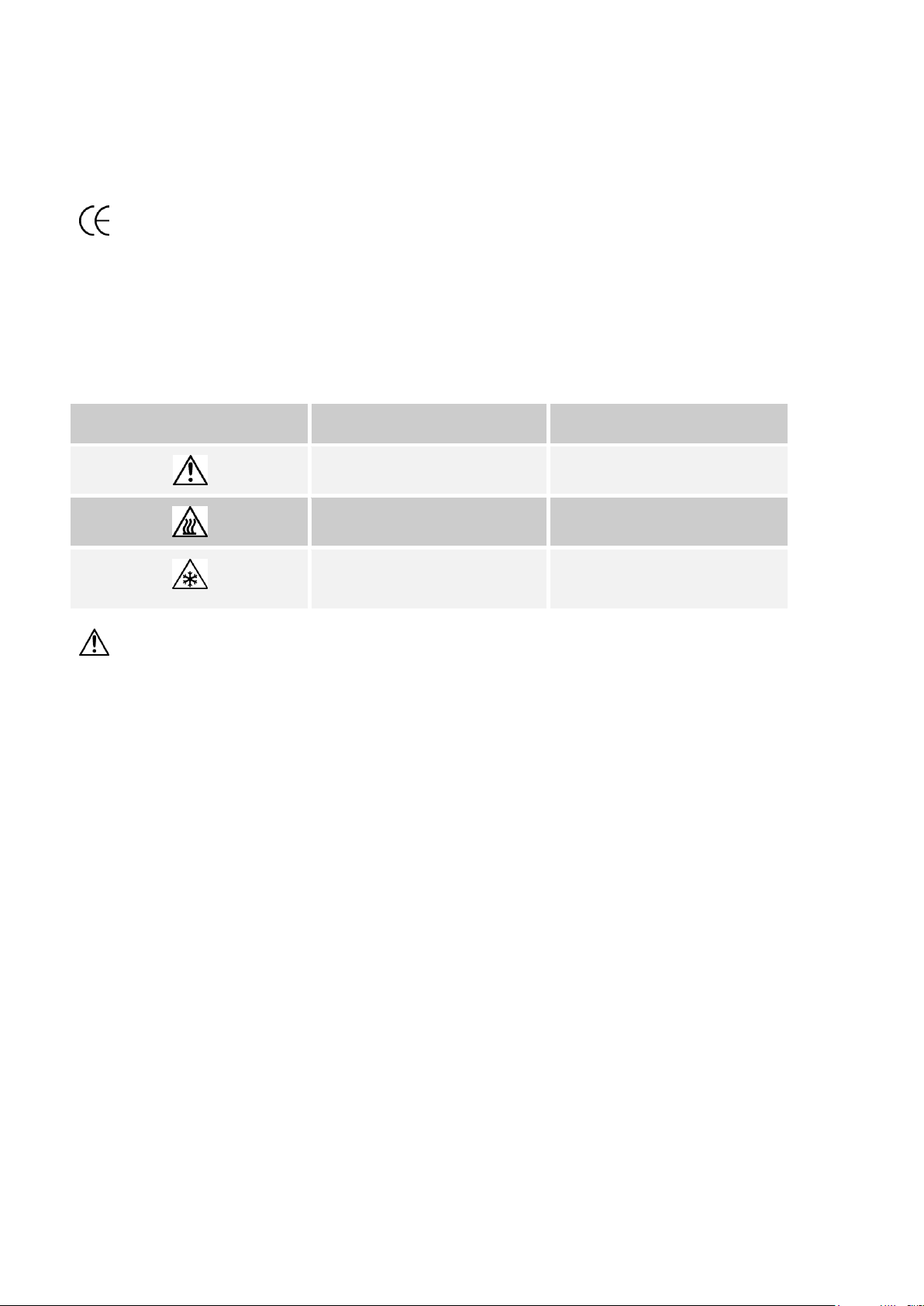
Symbol Identification
Publication
Description
ISO3864
Caution (refer to handbook)
IEC 417
Caution, Hot Surface
Caution, Low Temperature
Surface
ISSUE 1 – 02/10
EMC INFORMATION
This product meets the requirements of the European Directive on Electromagnetic Compatibility (EMC)
89/336/EEC as amended by EC Directive 92/31/EEC and the European Low Voltage Directive 73/25/EEC,
amended by 93/68/EEC. To ensure emission compliance please ensure that any serial communications
connecting leads are fully screened.
The product meets the susceptibility requirements of BSEN 61000-6-1:2001.
ELECTRICAL SAFETY
This equipment must be correctly earthed.
This equipment is a Class 1 Appliance. A protective earth is used to ensure the conductive parts can not
become live in the event of a failure of the insulation.
The protective conductor of the flexible mains cable which is coloured green/yellow MUST be connected to a
suitable earth.
The blue conductor should be connected to Neutral and the Brown conductor to Live (Line).
Warning: Internal mains voltage hazard. Do not remove the panels.
Page 4 of 22
Page 5

CRYO CALIBRATOR MODEL ISIS
ISSUE 1 – 02/10
GUARANTEE
This instrument has been manufactured to exacting standards and is guaranteed for twelve months against
electrical break-down or mechanical failure caused through defective material or workmanship, provided the
failure is not the result of misuse. In the event of failure covered by this guarantee, the instrument must be
returned, carriage paid, to the supplier for examination and will be replaced or repaired at our option.
FRAGILE CERAMIC AND/OR GLASS PARTS ARE NOT COVERED BY THIS GUARANTEE
INTERFERENCE WITH OR FAILURE TO PROPERLY MAINTAIN THIS INSTRUMENT MAY INVALIDATE
THIS GUARANTEE
RECOMMENDATION
The life of your ISOTECH Instrument will be prolonged if regular maintenance and cleaning to remove general
dust and debris is carried out.
ISOTHERMAL TECHNOLOGY LTD.
PINE GROVE, SOUTHPORT
PR9 9AG, ENGLAND
TEL: +44 (0) 1704 543830/544611
FAX: +44 (0)1704) 544799
The company is always willing to give technical advice and assistance where appropriate. Equally, because of
the programme of continual development and improvement we reserve the right to amend or alter
characteristics and design without prior notice. This publication is for information only.
Page 5 of 22
Page 6

CRYO CALIBRATOR MODEL ISIS
ISSUE 1 – 02/10
CAUTIONARY NOTE
ISOTECH PRODUCTS ARE INTENDED FOR USE BY TECHNICALLY TRAINED AND COMPETENT
PERSONNEL FAMILIAR WITH GOOD MEASUREMENT PRACTICES.
IT IS EXPECTED THAT PERSONNEL USING THIS EQUIPMENT WILL BE COMPETENT WITH THE
MANAGEMENT OF APPARATUS WHICH MAY BE POWERED OR UNDER EXTREMES OF
TEMPERATURE, AND ARE ABLE TO APPRECIATE THE HAZARDS WHICH MAY BE ASSOCIATED WITH,
AND THE PRECAUTIONS TO BE TAKEN WITH SUCH EQUIPMENT.
Page 6 of 22
Page 7

CRYO CALIBRATOR MODEL ISIS
ISSUE 1 – 02/10
HEALTH AND SAFETY INSTRUCTIONS
1. Read this entire handbook before use.
2. Wear appropriate protective clothing.
3. Operators of this equipment should be adequately trained in the handling of hot and cold items and
liquids.
4. Do not use the apparatus for jobs other than those for which it was designed, i.e. the calibration of
thermometers.
5. Do not handle the apparatus when it is hot or cold, unless wearing the appropriate protective
clothing and having the necessary training.
6. Do not drill, modify or otherwise change the shape of the apparatus.
7. Do not dismantle the apparatus without disconnecting it from the supply and leaving time for it to
reach ambient temperatures.
8. Do not use the apparatus outside its recommended temperature range
Page 7 of 22
Page 8

CRYO CALIBRATOR MODEL ISIS
CAUTION
1. Please use the insulated lid during the apparatus operation.
2. Always use a suitable insert for the application.
3. Take care when pressing the controller buttons. Do not use excessive force.
4. Only use the correct handles for lifting and moving.
5. Do not drop the equipment, this may sustain irreversible damage.
6. Take care when removing a sensor, especially if at low temperatures.
7. Please keep the distance between the apparatus and the back wall be more than 5cm.
8. Do not subject the equipment to intense electromagnet interference.
9. Do not obstruct the ventilation ducts.
10. If using alcohol, replace regularly to ensure performance.
11. Use alcohol sparingly.
12. This apparatus is designed for use in the following environment:
Indoor use only.
At less than 1000m altitude.
Ambient temperature range 0 ~ 35°C, relative humidity 30 ~ 85%RH.
No corrosive/flammable gases e.g. Do not use in an explosive atmosphere.
Power supply voltage is to be between the nominal voltage ±10%.
ISSUE 1 – 02/10
Page 8 of 22
Page 9

CRYO CALIBRATOR MODEL ISIS
ISSUE 1 – 02/10
INTRODUCTION
The Isis Dry Block offers operation to temperatures as low as -100°C, and is currently the only block bath
working to such a low temperature. Now it is possible to calibrate temperature sensors such as PRTs,
Thermocouples and Thermistors at ultra low temperatures without the need for a liquid bath.
Portability and Safety
Unlike a liquid bath the Isis requires no costly, or hazardous fluids and offers greater portability. This will be of
particular value to calibration engineers working on site with low temperature freezers as encountered in
pharmaceutical, aeronautical and food environments.
The minimum operating temperature is less than stirred liquid laboratory calibration baths and users in
laboratories will also benefit by avoiding the ongoing need for expensive fluids.
The maximum operating temperature is 40°C.
Cooling Technology
The Isis makes use of a Free Piston Stirling Cooler (FPSC) which provides a massive 80 Watts of cooling power
to the calibration block. Specialist materials, patent applied for, are used for the heat transfer from the FPSC to
the block.
Operating Life
Reliability is a prime attribute of this revolutionary new product. Testing at 20,000 hours (nominally equivalent
to 10 years at 40 hours use each week) shows that -100°C is still possible, with an increase in cooling time
<10%.
Benefits
Isotech can offer full support with options for UKAS / ILAC calibration, tutorial on getting the best calibration
uncertainties and a full range of supporting reference thermometers, indicators and software.
The Isis has a large insert 35mm diameter by 160mm deep. This allows for calibration of multiple sensors. For
thermal validation applications there is an insert with pockets for a reference probe (6.5mm) and 20 x 3.5mm
pockets for thermocouples. This allows a single calibration cycle to validate up to 20 probes at a time.
Page 9 of 22
Page 10

CRYO CALIBRATOR MODEL ISIS
ISSUE 1 – 02/10
UNPACKING AND INITIAL INSPECTION
This equipment uses custom designed packaging to send you your unit, but as accidents can still happen in
transit, you are advised, after unpacking the unit, to inspect it for any sign of shipping damage, and confirm that
your delivery is in accordance with the packing note. If you find any damage or that part of the delivery is
missing notify us or our agent, and the carrier immediately. If the unit is damaged you should keep the
packing for possible insurance assessment.
While this apparatus has already been inspected at the factory, please check as follows;
1. Read this ensure manual thoroughly.
2. Familiarise yourself with the layout of the equipment.
3. Connect to a suitable electrical supply and switch on.
4. The cooling fan should be heard and the controller illuminated during power up.
5. Check the function of the equipment using the quick start guide on next page (page 11).
Page 10 of 22
Page 11

CRYO CALIBRATOR MODEL ISIS
ISSUE 1 – 02/10
QUICK START GUIDE
This guide gives a general summary of the steps required to set the apparatus up and operate it.
This guide does not replace the manual and should be used only in conjunction with the correct manual
supplied with the bath.
ISIS control front panel
1. Place the required insert into the temperature well and place the insulated lid in place.
2. Connect the ISIS to a suitable power supply and power up.
3. After power up the controller will be active.
4. To select the desired temperature, follow the procedure below:
Allow the controller to boot up
Press the SET button momentarily and remove finger
The lower green display will read the current block temperature, the upper red display will display
the previous setpoint
Select the desired set point by pressing the SHIFT button, select the required digit and change the
value with the up/down buttons
Once the desired set point is displayed then press the SET button again to enter the value
Exit this level of the controller by pressing the RUN/STOP button for 5 seconds.
5. The FPSC engine can now be heard running as the equipment approaches setpoint
6. When finished select a further setpoint or switch off
Notes:
The RUN/STOP LED, indicated above, will illuminate when the unit is in heat/cooling mode. It will also blink
when the unit is in Autotune mode*
The ALARM LED is illuminated when the unit temperature is in excess of 50°C or below -114°C for a period in
excess of 3 minutes
The STATUS LED is illuminated when the bath temperature is stable to within +/- 0.3°C of the setpoint for a
period in excess of 3 minutes
Page 11 of 22
Page 12

C
D
A B
E
USING THE ISIS
Controller Panel
CRYO CALIBRATOR MODEL ISIS
ISSUE 1 – 02/10
A. Alarm LED
B. Status LED
C. Block temperature display
D. Set point temperature display
E. Heating/Cooling enable
Page 12 of 22
Page 13

ISIS GENERAL ARRANGEMENT
CRYO CALIBRATOR MODEL ISIS
ISSUE 1 – 02/10
A. Control panel
B. Mains electrical socket
C. PC communications socket
D. Insulated thermowell cover
E. Carry handles
F. Air ventilation
Page 13 of 22
Page 14

Item
Operation
PV
Upper Red Display
Displays temperature in metal block bath
SV
Lower Green Display
Displays set temperature
Status LED
Iluminated when the bath temperature is stable to within ±0.3°C for setpoint for 3
minutes
Alarm LED
Iluminated when bath temperature exceeds +50°C or -114°C for 3 minutes
Run LED
Iluminated when bath is running normally, blinks during auto tune mode
Run/Stop Switch
Holding down key for 5 seconds will enable/disable cooling/heating
Set Switch
(1) In precontrol mode, allow access to internal pyrameters by pressing for 5 seconds
(2) Press to input data
Shift Switch
Multifunctional switch to allow:
(1) Auto tuning.
(2) Move the cursor during setpoint selection
Down Switch
Allows decreasing values to be entered
Up Switch
Allows increasing vlaues to be entered
ISIS FUNCTION
Operation Mode
CRYO CALIBRATOR MODEL ISIS
ISSUE 1 – 02/10
Page 14 of 22
Page 15

CRYO CALIBRATOR MODEL ISIS
ISSUE 1 – 02/10
OPERATIONAL PROCEDURE
Basic Operation
Step 1. Power up the equipment with a suitable electrical supply
Step 2. Initializing the apparatus
Upper bar of the Red Display and Alarm LED illuminate for 5 seconds
Step 3. The block temperature is displayed on the Red Display
Step 4. Set temperature is displayed on the smaller Green Display
Step 5. After setting the setpoint, press the Run/Stop switch for 5 seconds and the cooling/heating operation
starts
Run LED goes “ON”
Controller Levels Of Operation
Precontrol Mode
After power-up, the controller will go through a self-test and finally display the set temperature and the actual
temeprature. The heating/cooling is not yet enabled. This is the Pre-control Mode.
Input SV Mode
From the Pre-control mode, press the “Set” button momentarily. The upper display will show the set
temperature and the lower display will show the current block temperature. This is the Input SV Mode.
This allows the set temperature to be changed.
Input Settings Mode
From the Pre-control mode, press and hold the “Set” button for 5 seconds. The upper display will read the
current set temperature and the lower display will read “trEF”. This is the Settings Mode.
Page 15 of 22
Page 16

Parameter
Display
Upperlimit
Lowerlimit
SV
trEF
+50.0
-100.0
Proportional Band
Prop
50.0
0
Integral Gain
Iteg
5000
0
Derivative Gain
Deri
5000
0
Proportiona Gain
Regi
100 0 Temperature Offset
Offs
9.99
-9.99
Gain Offset
gain
5000
-5000
Detailed Input Settings Mode
For access to this level refer to previous page (page 15).
Use the UP/DOWN buttons to scroll through the menu, listed below.
CRYO CALIBRATOR MODEL ISIS
ISSUE 1 – 02/10
To access a value press the “UP/DOWN” buttons to locate the value. Once located press the “Set” button
to allow access. Then the UP/Down button to adjust the value and when complete, press the “Set” button
again to store the value.
To exit this level press and hold the “RUN/STOP” button for 5 seconds to revert back to Pre-control mode.
Auto Tune Mode
To initiate an “Auto Tune Run” press and hold the shift switch for 5 seconds. The temperature difference
between setpoint and block temperature must be greater than 6°C to initate the Auto Tune mode.
It is recommended to use the factory installed PID values and only run the Auto Tune mode if these values are
changed or the equipment has different “loading” than normal.
Alarm Mode
The Alarm LED will flash if the block temperature exceeds 50°C or drops below -114°C for a period of 3
minutes.
Status
The Status LED will flash when the block temperature is stable within ±0.3°C of the setpoint for 3 minutes.
Page 16 of 22
Page 17

SELECTING A SETPOINT
CRYO CALIBRATOR MODEL ISIS
ISSUE 1 – 02/10
Page 17 of 22
Page 18

CRYO CALIBRATOR MODEL ISIS
ISSUE 1 – 02/10
CAL NOTEPAD
Cal Notepad can be used to log and display values from the unit and an optional temperature indicat
or.
Minimum System Requirements
CNP requires Windows 9X, XP, a minimum of 5Mb of free hard drive space and free serial ports fo
r the instruments to be connected.
Development
CNP was developed by Isothermal Technology using LabVIEW from National Instruments.
License
Use of the Cal NotePad software program "CNP" is as granted in this license agreement. In using the CNP soft
ware the user "licensee" is agreeing to the terms of the license. You must read and understand the terms of th
is license before using CNP.
1, This license permits licensee to use CNP software on a single computer. The user may make copies for bac
k up and archival purposes freely as long as the software is only ever in use on a single computer at any one
time. Please enquire about multi-user licenses.
2, CNP is protected by international copyright laws and treaties. CNP must not be distributed to third parties.
3, CNP must not be reversed engineered, disassembled or de-compiled. Licensee may transfer the software to
a third party provided that no copies or upgrades of CNP are retained.
4, It is the responsibility of the user to ensure the validity of all stored results and printed certificates. Isother
mal Technology Ltd accept no responsibility for any errors caused by inappropriate use, incorrect set up or an
y other cause; including defects in the software.
5, Limited Warranty. Isothermal Technology warrants that CNP will perform substantially as described in this ma
nual for a period of 90 days from receipt. Any distribution media will under normal used be guaranteed for a p
eriod of 90 days.
NO OTHER WARRANTIES, EXCEPT AS STATED ABOVE. The software and documentation is provided "as is"
without warranty of any kind and no other warranties (either expressed or implied) are made with regard to C
NP. Isothermal Technology does not warrant, guarantee or make any representations regarding the use or result
s of the use of the software or documentation and does not warrant that the operation of CNP will be error
free.
In no event will Isothermal Technology, its employees, agents or other associated people be liable for direct, in
direct, incidental or consequential damages, expenses, lost profits, business interruption, lost business information
or other damages arising out the use or inability to use CNP. The license fee reflects this allocation of risk.
CNP is not designed for situations where the results can threaten or cause injury to humans.
Page 18 of 22
Page 19

CRYO CALIBRATOR MODEL ISIS
ISSUE 1 – 02/10
Installing Cal NotePad
1. Insert Isotech Support CD into the CD drive.
2. Allow CD browser to open and install version of Cal NotePad required.
3. Follow the prompts which will install the application and necessary LabVIEW run time support files.
4 Should you ever need to uninstall the software then use the Add/Remove Programs option fro
m the Control Panel.
Starting Cal NotePad
From a Standard Installation:
Click the START button
Highlight PROGRAMS
Select Isotech - Select Calpad
Protocol
The instruments use the "Modbus Protocol"
If required, e.g. for writing custom software the technical details are available from our website at, w
ww.isotech.co.uk/refer.html
Page 19 of 22
Page 20

Voltage
100 ~ 240 10% Vac
Power
200VA
Supply Frequency
50/60Hz
Maximum Operating Temperature
40°C
Minimum Operating Temperature
-100°C
Calibration Volume
ø35mm×160mm deep
Sensor insert Hole Dimension
ø9.5 mm ×1pc + φ8 mm×1pc
ø6.4 mm ×2pc + φ4.5 mm×2pc
Hole depth is 157 mm.
Operation temperature
0 ~ 35°C
Operation Relative humidity
30 ~ 85%RH (non condensing)
Storage temperature
-10 ~ 50°C
Temperature Display resolution
0.01°C self ranging to 0.1°C
Dimensions
Height 420mm
Width 215mm
Depth 630mm
Weight
20Kg
SPECIFICATION
CRYO CALIBRATOR MODEL ISIS
ISSUE 1 – 02/10
Page 20 of 22
Page 21

Communication Settings
Communication
RS232C
Communication lines
3 lines
Control line
None
Length of PC communication cable
10m (2m Recommended)
Baud rate
9600bps
Method
Half duplex
Communication parameter
8bit
NonParity
StopBit=1
Communication character
ASCII code
Connecter
9pin Dsub male Connecter
Pin Assign
2pin = RXD
3pin = TXD
5pin = GND
7pin, 8pin Jumped
COMMUNICATION
CRYO CALIBRATOR MODEL ISIS
ISSUE 1 – 02/10
Regarding the detailed specification, please contact Isotech.
Page 21 of 22
Page 22

STANDARD PARTS LIST
Body
Power cable
Metal insert block
Extracting tool for insert block
Lid for the calibration block
User Maintenance manual/handbook
CRYO CALIBRATOR MODEL ISIS
ISSUE 1 – 02/10
Page 22 of 22
 Loading...