

Page 1
Instruction Manual
300XP
Portable Thermal Printer
FREN
IT
DE
ES
ʳ
ʳ
Africa
Iso-Tech
1 & 2 Indianapolis Street
Kyalami Business Park
Kyalami, Midrand, South Africa
Asia
Iso-Tech
460 Alexandra Road, #15-01A
PSA Building
Singapore 119963
Europe
Iso-Tech
PO Box 99
Corby
Northamptonshire
NN17 9RS
United Kingdom
Japan
West Tower (12th Floor)
Yokohama Business Park
134 Godocho, Hodogaya
Yokohama, Kanagawa 240-0005 Japan
USA
7410 Pebble Drive
Fort Worth
Texas 76118-6961
Canada
1701 Woodward Drive
Ste 108 Ottawa
Ontario K2C 0R4, Canada
South America
Av. Pdte. Eduardo Frei M. 6001-71
Centro Empresas El Cortijo
Conchali, Santiago, Chile
Page 2
PRINTER DESCRIPTION / EN
05/20/2010 Version No. 1.0 EN-33ʳ
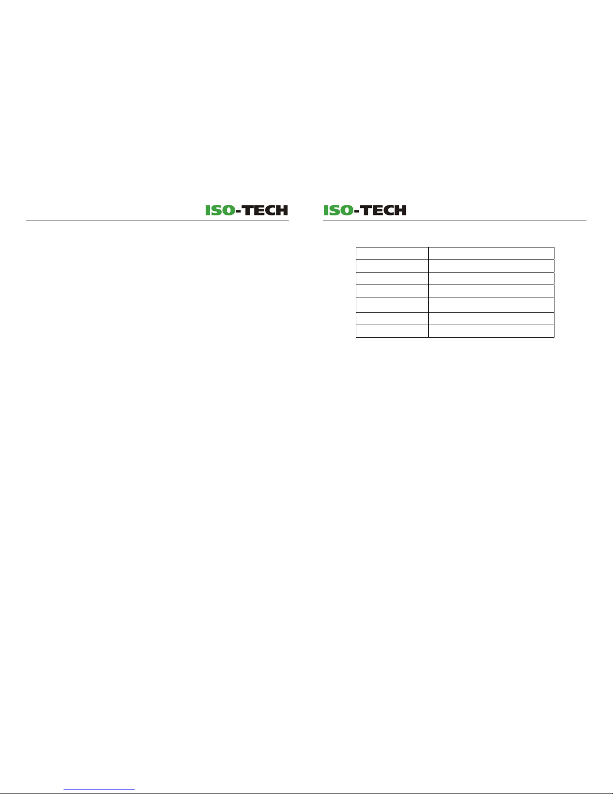
6.3 Mechanical and Environmental Specifications
Operating Temperature:
10 to +50°C
Storage Temperature: 20 to +60°C
Humidity: 0 to 90%RH (Non-condensing)
Battery: 8 x 1.5V (AA)
AC Power Adaptor:
Input: 100 to 240V a.c., 50 to 60 Hz, 0.2A
Output: 12V d.c. 0.5A
Dimension: W95 x D135 x H55mm
Weight: 440g (including 8 batteries)
CONTENTS / EN
05/20/2009 Version No. 1.0ʳ
EN-II
1 Printer Description ..............................................................................1
2 Connection...........................................................................................3
2.1 Using the OP (optically isolated) connecting port (for
connection to ISO-TECH instruments)..................................... 3
2.1.1 ISO-TECH IPM3005 Flexible Power Quality Tester ......... 3
2.1.2 ISO-TECH 6200 Graphic Power Quality Analyzer........... 4
2.1.3 ISO-TECH 6300 Graphic Power Quality Analyzer........... 5
2.2 To use the RS232 connecting port............................................6
2.2.1 AVM-09 Anemometer.........................................................6
2.3 To Connect with Agilent® 34401A ............................................7
2.3.1 Setting Agilent® 34401A ...................................................7
2.3.2 To Connect with Agilent® 34401A Multi-meter ............... 9
2.3.3 Agilent Buttons Description ...........................................10
3 Operation Description....................................................................... 11
3.1 Setting the Printing Contrast .................................................. 11
3.2 Dip Switch Description ............................................................12
3.3 Replacing the Batteries ...........................................................14
3.4 Replacing the Thermal Paper roll ...........................................15
4 Software Installation and Operation ................................................ 18
4.1 Software Installation ................................................................ 18
4.2 Setting the Connecting Port....................................................19
4.3 Graphics Printing ..................................................................... 19
4.4 Text Printing.............................................................................. 20
4.5 Programming Text Header and Footer...................................21
5 Appendix ............................................................................................22
5.1
ΰ
Appendix IαPC Command for Printer................................22
5.2
ΰ
Appendix IIαCoding of Graphics Printing......................... 23
5.3
ΰ
Appendix IIIαRS-232 Pin Connections ..............................24
5.4
ΰ
Appendix IVαASCII Code Tables........................................25
6 Specifications ....................................................................................32
6.1 Printing Mechanical specifications ........................................ 32
6.2 Communication Specifications ............................................... 32
6.3 Mechanical and Environmental Specifications .....................33
ʳ
Page 3
PRINTER DESCRIPTION / EN
05/20/2010 Version No.1.0 EN-1
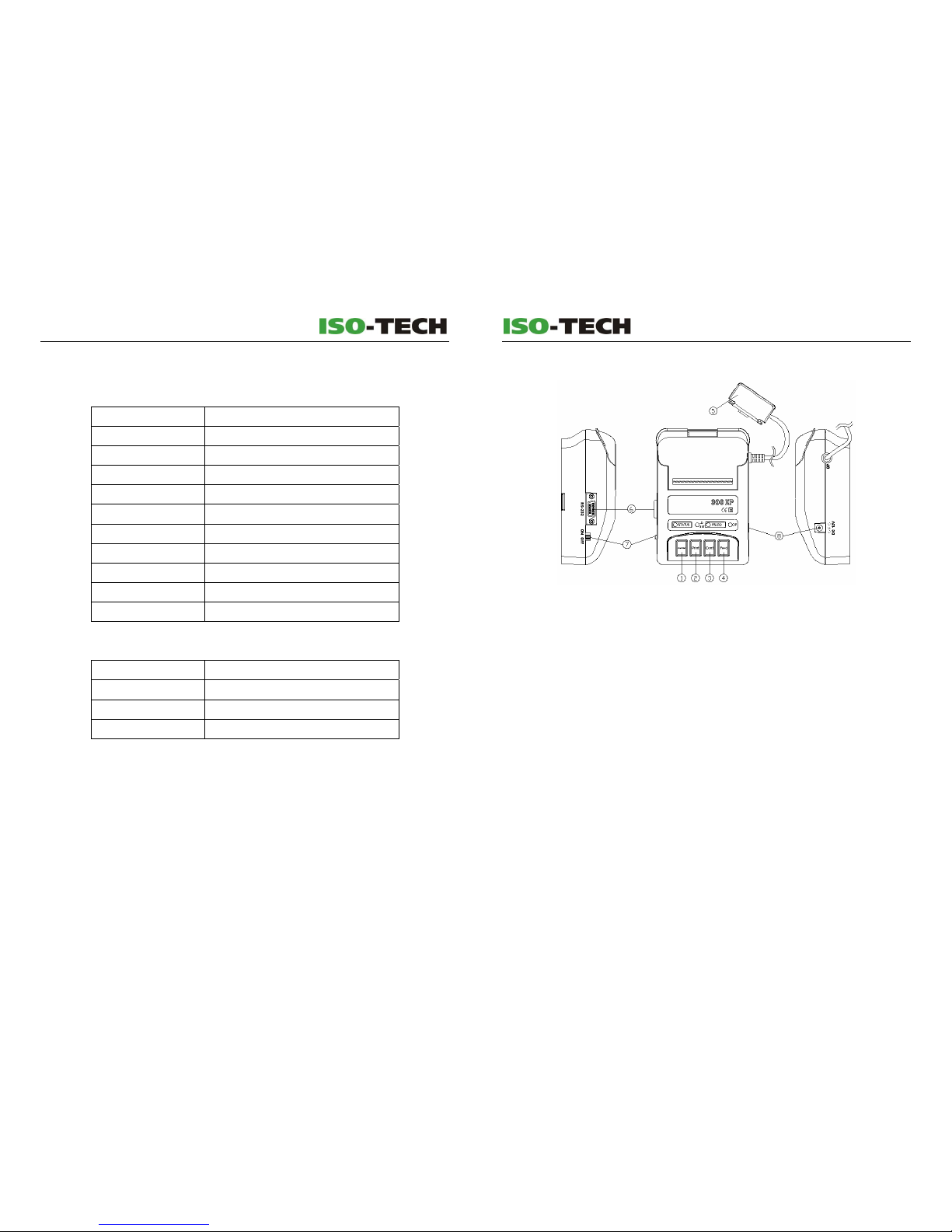
1 Printer Description
1. Cancel button: When pressed, printing is stopped immediately.
2. Print button: When pressed, data is fetched from the instrument and printed,
including the Header and Footer.
3. Cont button: When pressed, data is fetched from the instrument and printed
automatically but without header and footer, depending on the selected print interval
- refer to DIP Switches SW4 & SW5.
4. Feed button: Line-feed - paper moves up one line.
5. Optically isolated connecting cable.
6. RS232 connecting port.
7. Power switch.
8. Socket: 12V dc power socket – centre positive
PRINTER DESCRIPTION / EN
EN-32
05/20/2010 Version No. 1.0
ʳ
6 Specifications
6.1 Printing Mechanical specifications
Method: Thermal Dot-matrix Printing
Dot per Line: 8 (Vertical) x 166 (Horizontal)
Fonts: 5 x 7 and 10 x 15
Dot Pitch: 0.35mm (Vertical), 0.28mm (Horizontal)
Character Size: 1.4 x 2.4mm (5x7), 2.8 x 4.6mm (10x15)
Characters per Line: 27 (5x7), 16 (10x15)
Printing Contrast: Automatic or user-selectable.
Printing Width: 46mm
Printing Speed: 0.8 lines / second
Printing Life: 500,000 lines
Paper roll size:
57mm wide x 28 mm ӿ
6.2 Communication Specifications
Interface: RS-232C (9,600, 8, 1, N)
Receiving Buffer: 9K bytes
Character Set: ASCII International
Graphics: Bit Map (160*400)
Page 4

PRINTER DESCRIPTION / EN
05/20/2010 Version No.1.0 EN-31
231 E7 347
Decimal Hexadecimal Octal ASCII
232 E8 350
233 E9 351
234 EA 352
235 EB 353
236 EC 354
237 ED 355
238 EE 356
239 EF 357
240 F0 360
241 F1 361 ±
242 F2 362
243 F3 363
244 F4 364
245 F5 365
246 F6 366 ÷
247 F7 367
248 F8 370
249 F9 371
250 FA 372
251 FB 373
252 FC 374
253 FD 375
254 FE 376
255 FF 377
PRINTER DESCRIPTION / EN
EN-2
05/20/2010 Version No. 1.0
ʳ
ʳ
ʳ
9. Printer upper cover.
10. Printer base.
11. Battery cover.
12. Paper cover.
13. Paper exit: Printed paper will emerge from this exit and can be torn off against the
serrated cutting edge.
14. Paper trough: Cavity for the roll of thermal paper.
15. Dip switches: Used to select printing interval, character size & input modes – refer
to section 3.2 for details
16. STATUS LED: When the connection is via RS232 and this LED blinks,
the printer is
awaiting connection to the host instrument. When this LED is off, connection is
established.
17. Low battery LED: When lit, the internal batteries are low and should be replaced refer to section 3.3.
18. RS232 Status LED: When lit, connection is via the RS232 port.
19. OP Status LED: When lit indicates connection is via the optically isolated port.
20. Rubber feet: Prevent the printer sliding on smooth surfaces.
ʳ
Page 5

PRINTER DESCRIPTION / EN
05/20/2010 Version No.1.0 EN-3
2 Connection
2.1 Using the OP (optically isolated) connecting port
(for connection to ISO-TECH instruments)
2.1.1 ISO-TECH IPM3005 Flexible Power Quality Tester
1. Ensure the 300XP printer is turned off.
2. Set the DIP switch of the printer SW1 to ON.
3. Connect the OP cable of the printer to the optical port on the host instrument (Refer
to the instructions for the host instrument for further information).
4. Turn the host instrument power on.
5. Turn on the printer.
6. Ensure the status LED of the printer is off.
7. Connection is now complete.
8. Press the Print button for single event printing (including Header and Footer), or
Press the Cont button for continuous printing (excluding Header and Footer)
9. If the connection fails, turn off the printer and host instrument and then repeat steps
4~6 above.
Printing example:
ʳ
ʳ
ʳ
PRINTER DESCRIPTION / EN
EN-30
05/20/2010 Version No. 1.0
ʳ
Decimal Hexadecimal Octal ASCII
197 C5 305
198 C6 306
199 C7 307
200 C8 310
201 C9 311
202 CA 312
203 CB 313
204 CC 314
205 CD 315
206 CE 316
207 CF 317
208 D0 320
209 D1 321
210 D2 322
211 D3 323
212 D4 324
213 D5 325
214 D6 326
215 D7 327
216 D8 330
217 D9 331
218 DA 332
219 DB 333
Ѡ
5*7 full
220 DC 334
5*4 top
221 DD 335
ў
3*7 left
222 DE 336
3*7 right
223 DF 337
і
5*7 bottom
224 E0 340
225 E1 341
226 E2 342
227 E3 343
228 E4 344
229 E5 345
230 E6 346
Page 6

PRINTER DESCRIPTION / EN
05/20/2010 Version No.1.0 EN-29
Decimal Hexadecimal Octal ASCII
163 A3 243 (spare)
164 A4 244 (spare)
165 A5 245 (spare)
166 A6 246 (spare)
167 A7 247 (spare)
168 A8 250 (spare)
169 A9 251 (spare)
170 AA 252 (spare)
171 AB 253 (spare)
172 AC 254 (spare)
173 AD 255 (spare)
174 AE 256 (spare)
175 AF 257 (spare)
176 B0 260 (spare)
177 B1 261 (spare)
178 B2 262 (spare)
179 B3 263
180 B4 264
181 B5 265
182 B6 266
183 B7 267
184 B8 270
185 B9 271
186 BA 272
187 BB 273
188 BC 274
189 BD 275
190 BE 276
191 BF 277
192 C0 300
193 C1 301
194 C2 302
195 C3 303
196 C4 304
PRINTER DESCRIPTION / EN
EN-4
05/20/2010 Version No. 1.0
ʳ
2.1.2 ISO-TECH 6200 Graphic Power Quality Analyzer
1. Ensure the 300XP printer is turned off.
2. Set the DIP switch of the printer: SW1 to ON.
3. Connect the OP cable of the printer to the optical port on the host instrument (Refer
to the instructions for the host instrument for further information).
4. Turn the host instrument power on.
5. Turn on the printer.
6. Ensure the status LED of the printer is off.
7. Connection is now complete.
8. Press the Print button for single event printing (including Header and Footer), or
Press the Cont button for continuous printing (excluding Header and Footer)
9. If the connection fails, turn off the printer and host instrument and then repeat steps
4~6 above.
Printing example:ʳ
ʳ
ʳ
ʳ
Page 7

PRINTER DESCRIPTION / EN
05/20/2010 Version No.1.0 EN-5
2.1.3 ISO-TECH 6300 Graphic Power Quality Analyzer
1. Ensure the 300XP printer is turned off.
2. Set the DIP switch of the printer: SW1 to ON.
3. Connect the OP cable of the printer to the optical port on the host instrument (Refer
to the instructions for the host instrument for further information).
4. Turn the host instrument power on.
5. Turn on the printer.
6. Ensure the status LED of the printer is off.
7. Connection is now complete.
8. Press the Print button for single event printing (including Header and Footer), or
Press the Cont button for continuous printing (excluding Header and Footer)
9. If the connection fails, turn off the printer and host instrument and then repeat steps
4~6 above.
Printing example:ʳ
ʳ
ʳ
ʳ
PRINTER DESCRIPTION / EN
EN-28
05/20/2010 Version No. 1.0
ʳ
Decimal Hexadecimal Octal ASCII
130 82 202
131 83 203
132 84 204
133 85 205
134 86 206
135 87 207
136 88 210
137 89 211
Տ
138 8A 212
ᩉ
139 8B 213
ց
140 8C 214
կ
141 8D 215 × (multiplication sign)
142 8E 216
X
143 8F 217
Y
144 90 220
Z
145 91 221
146 92 222
147 93 223
148 94 224
149 95 225
150 96 226
151 97 227
152 98 230
153 99 231
154 9A 232
(lightning sign)
155 9B 233 (spare)
156 9C 234 (spare)
157 9D 235 (spare)
158 9E 236 (spare)
159 9F 237 (spare)
160 A0 240 (spare)
161 A1 241 (spare)
162 A2 242 (spare)
Page 8

PRINTER DESCRIPTION / EN
05/20/2010 Version No.1.0 EN-27
Decimal Hexadecimal Octal ASCII
96 60 140 `
97 61 141 a
98 62 142 b
99 63 143 c
100 64 144 d
101 65 145 e
102 66 146 f
103 67 147 g
104 68 150 h
105 69 151 i
106 6A 152 j
107 6B 153 k
108 6C 154 l
109 6D 155 m
110 6E 156 n
111 6F 157 o
112 70 160 p
113 71 161 q
114 72 162 r
115 73 163 s
116 74 164 t
117 75 165 u
118 76 166 v
119 77 167 w
120 78 170 x
121 79 171 y
122 7A 172 z
123 7B 173 {
124 7C 174 |
125 7D 175 }
126 7E 176 ~
127 7F 177
128 80 200
129 81 201
PRINTER DESCRIPTION / EN
EN-6
05/20/2010 Version No. 1.0
ʳ
2.2 To use the RS232 connecting port
2.2.1 AVM-09 Anemometer
1. Ensure the 300XP printer and AVM-09 Anemometer are turned off.
2. Set the dip switches of the printer: SW1 to OFF and SW2 to ON.
3. Connect the RS232 cable to the anemometer and the printer.
4. Press and hold button “1” (HOLD/RS-232) on the anemometer and then press the
power button to turn it on. After 1 second, release button “1” and the anemometer
LCD should display “RS-232” to confirm the RS-232 mode is enabled (Refer to the
anemometer instructions for further information).
5. Turn on the printer.
6. Ensure the status LED of the printer is off.
7. Connection is now complete.
8. Press the Print button for single event printing (including Header and Footer), or
Press the Cont button for continuous printing (excluding Header and Footer)
9. If the connection fails, turn off the printer and the anemometer and then repeat steps
4~6 above.
Printing example:
ʳ
ʳ
Page 9

PRINTER DESCRIPTION / EN
05/20/2010 Version No.1.0 EN-7
2.3 To Connect with Agilent® 34401A
2.3.1 Setting Agilent® 34401A
1. Enter the Agilent 34401A MENU:
Press
then
press
to enter MENU.
2. Enter E: I/O MENU
Press
to go to E: I/O MENU –
sub-functions, then press
to enter.
3. Press
to select Setting 1: GPIB ADDR, its value = 31: TALK ONLY
Press
then
press
to select setting
position, then press
to change the value = 31 (TALK ONLY), after
finishing setting press
to save the setting.
4. Press
to select Setting 2: INTERFACE, its value = RS-232.
(First repeat steps 1~2)
Press
then
press
to change the setting
value = RS-232,
then press
to save the settings.
ʳ
5. Press
to select Setting 3: BAUD RATE, its value = 9600 BAUD.
(First repeat steps 1~2)
Press
then
press
to change the setting
value = 9600 BAUD.
Then press
to save the settings.
6. Select Setting 4: PARITY, its value = NONE: 8 BITS (First repeat steps 1~2)
7. Select Setting 4: LANGUAGE to be the format for printing (First repeat
steps 1~2).
PRINTER DESCRIPTION / EN
EN-26
05/20/2010 Version No. 1.0
ʳ
61 3D 75 =
62 3E 76 >
63 3F 77 ?
64 40 100 @
65 41 101 A
66 42 102 B
67 43 103 C
68 44 104 D
69 45 105 E
70 46 106 F
71 47 107 G
72 48 110 H
73 49 111 I
74 4A 112 J
75 4B 113 K
76 4C 114 L
77 4D 115 M
78 4E 116 N
79 4F 117 O
80 50 120 P
81 51 121 Q
82 52 122 R
83 53 123 S
84 54 124 T
85 55 125 U
86 56 126 V
87 57 127 W
88 58 130 X
89 59 131 Y
90 5A 132 Z
91 5B 133 [
92 5C 134 \
93 5D 135 ]
94 5E 136 ^
95 5F 137 _
Page 10

PRINTER DESCRIPTION / EN
05/20/2010 Version No.1.0 EN-25
5.4ΰAppendix IVαASCII Code Tables
There are 199 fonts for printing selection.
Decimal Hexadecimal Octal ASCII
32 20 40 (space)
33 21 41 !
34 22 42 "
35 23 43 #
36 24 44 $
37 25 45 %
38 26 46 &
39 27 47 '
40 28 50 (
41 29 51 )
42 2A 52 *
43 2B 53 +
44 2C 54
Δ
45 2D 55 -
46 2E 56 .
47 2F 57 /
48 30 60 0
49 31 61 1
50 32 62 2
51 33 63 3
52 34 64 4
53 35 65 5
54 36 66 6
55 37 67 7
56 38 70 8
57 39 71 9
58 3A 72
Κ
59 3B 73 ;
60 3C 74 <
ʳ
Decimal Hexadecimal Octal ASCII
PRINTER DESCRIPTION / EN
EN-8
05/20/2010 Version No. 1.0
ʳ
Note:
Agilent is a trade mark of Agilent Technologies.
ʳ
Page 11

PRINTER DESCRIPTION / EN
05/20/2010 Version No.1.0 EN-9
2.3.2 To Connect with Agilent® 34401A Multi-meter
1. Ensure the 300XP printer and Agilent 34401A multimeter are turned off.
2. Set the dip switches of the printer: SW1 to OFF and SW2 to ON.
3. Connect the RS232 cable to the multimeter and the printer.
4. Turn on the multimeter.
5. Turn on the printer.
6. If the LCD of the multimeter shows ERROR, ignore it and continue.
7. Ensure the status LED of the printer is off.
8. Connection is now complete.
9. Press the Print button for single event printing (including Header and Footer), or
Press the Cont button for continuous printing (excluding Header and Footer)
10. If the connection fails, turn off the printer and the multimeter and then repeat steps
4~6 above.
Printing example:
ʳ
ʳ
ʳ
ʳ
PRINTER DESCRIPTION / EN
EN-24
05/20/2010 Version No. 1.0
ʳ
5.3ΰAppendix IIIαRS-232 Pin Connections
ʳ
ʳ
Page 12

PRINTER DESCRIPTION / EN
05/20/2010 Version No.1.0 EN-23
5.2ΰAppendix IIαCoding of Graphics Printing
ʳ
ʳ
ʳ
PRINTER DESCRIPTION / EN
EN-10
05/20/2010 Version No. 1.0
ʳ
2.3.3 Agilent Buttons Description
Select the setting sub-functions, or change the settings.
Enter the setting sub-functions, or change the settings.
Save the settings.
Select the setting sub-functions, or change the settings.
Exit the setting sub-functions, or change the settings.
Enter / Exit the function table.
ʳ
ʳ
ʳ
Page 13

PRINTER DESCRIPTION / EN
05/20/2010 Version No.1.0 EN-11
3 Operation Description
3.1 Setting the Printing Contrast
Cancel
Print
Cont
Feed
1. Ensure the 300XP printer is turned off.
2. To select the contrast:
Press and hold the following button(s) for 1 second while turning the printer power
on.
(1) Press Cont and Feed buttons at the same time: the contrast is the strongest.
(2) Press Cont button: the contrast is stronger (+2).
(3) Press Feed button: the contrast is strong (+1).
(4) Press nothing: the contrast is normal (0).
(5) Press Print button: the contrast is light (-1).
(6) Press Cancel button: the contrast is lighter (-2).
(7) Press Cancel and Print buttons at the same time: the contrast is the lightest (-3).
3. When the button(s) are released, the contrast setting is complete.
PRINTER DESCRIPTION / EN
EN-22
05/20/2010 Version No. 1.0
ʳ
5 Appendix
5.1
ΰ
Appendix IαPC Command for Printer
Command Remark
1 00
(16)
(Text String) 0D
(16)
Text printing
2 07
(16)
XXXX 0D
(16)
YY
(XXXX)
Graphics printing
3 01
(16)
(Head String) FF
(16)
FF
(16)
0D
(16)
Text setting (printing) of header
4 06
(16)
(Foot String) FF
(16)
FF
(16)
0D
(16)
Text setting (printing) of
Footer
5 02
(16)
Inquiry of printer availability
6 09
(16)
Inquiry of how many bytes left
to be printed
7 0A
(16)
Line-feed (Skip a line)
Remark:
1. For text printing, the Text String is the text for printing.
2. For graphics printing, it is necessary to code the printing file first. The file should be
160*400-dot black/white graphics.
The coding is as below: (refer to Appendix II)
(1) The coding of graphics is from left to right and from top to bottom.
(2) 8 dots are shown as 1 byte (YY) for coding.
(3) The maximum printed file size is a coded black/white graphics file of 160 * (400 /
8) = 8000 bytes
(4) XXXX is the data byte after coding.
(5) For example:
07
(16)
0320 0D
(16)
3d
(0001)
0C
(0002)
22
(0003)
49
(0004)
…. …. …. …. 00
(0317)
ff
(0318)
3d
(0319)1a(0320)
3. The Head String is the head text for printing.
4. The Foot String is the foot text for printing.
5. The printer will only respond to an enquiry if it is idle. If the printer is busy, it will
respond 02
(16).
When printing is finished and await further commands.
6. If queried, the printer will advise how many bytes remain to be printed.
7. Line feed (The printer skips a line).
Page 14

PRINTER DESCRIPTION / EN
05/20/2010 Version No.1.0 EN-21
4.5 Programming Text Header and Footer
1. Type in the text for Header under Report Head Text String.
2. Click on the Send button to finish the setting.
3. Type in the text for Footer under Report Foot Text String.
4. Click on the Send button to finish the setting.
PRINTER DESCRIPTION / EN
EN-12
05/20/2010 Version No. 1.0
ʳ
3.2 Dip Switch Description
Swi tc h
0
1
SW1
SW2
SW3
Communicat ion
Mode
Font
RS- 23 2
Compu t er
Big
OP
Meter
Sma l l
SW4 SW5 Cont
0
0
0
0
1
1
1
1
300sec
60sec
30sec
5sec
1. SW1 Communication: select the communication method.
z OP: use the optically isolated connecting cable of the 300XP printer to
connect to some models of ISO-TECH Instruments.
z RS232: use the RS232 port/cable of the 300XP printer to connect to a PC,
Agilent 34401A multimeter and some models of RS instruments.
2. SW2 Mode: Select the connecting device.
z Computer: Use the application program supplied with the 300XP printer to
produce text or graphics.
z Meter: Other instruments, including some ISO-TECH and RS
instruments
mentioned in this manual as well as the Agilent 34401A Multi-meter.
ʳ
Page 15

PRINTER DESCRIPTION / EN
05/20/2010 Version No.1.0 EN-13
3. SW3 FontΚSelect the font size required.
z Small Font: 5*7 dots
z Big Font: 10*15 dots
4. SW4 and SW5: Select the printing interval for continuous printing.
z 5s: 1 print operation every 5 seconds.
z 30s: 1 print operation every 30 seconds.
z 60s: 1 print operation every 1 minute.
z 300s: 1 print operation every 5 minutes.
Note: Set the dip switches with the printer power turned off. The new settings will be
applied when the printer power is next turned on.
ʳ
PRINTER DESCRIPTION / EN
EN-20
05/20/2010 Version No. 1.0
ʳ
2. Preview the graphics file under Picture preview.
3. Click on the Print button to print the graphics files.
ʳ
Note: The graphics files for printing should be
single-colour Monochrome Bitmap (.bmp) only
.
ʳ
ʳ
4.4 Text Printing
1. Type in the text for printing under Text String. (Refer to Appendix IV)
2. Click on the Print button to print the text.
ʳ
ʳ
ʳ
Page 16

PRINTER DESCRIPTION / EN
05/20/2010 Version No.1.0 EN-19
4.2 Setting the Connecting Port
1. Under the VISA resource name, click on the drop-down box and select the
required connecting port.
2. Click on the Change button to confirm (modify) the connecting port.
4.3 Graphics Printing
1. Select the required graphics file for printing under Picture Path.
PRINTER DESCRIPTION / EN
EN-14
05/20/2010 Version No. 1.0
ʳ
3.3 Replacing the Batteries
When the LO BAT LED is lit, replace the exhausted batteries with new ones as follows.
Do not leave exhausted batteries in the printer as they may leak and cause damage to
the printer.
1. Use a screwdriver to remove the screw from the battery cover.
2. Remove the battery cover. Retain the screw and cover.
3. Remove the exhausted batteries.
4. Fit Qty. 8 new batteries (1.5V, AA type) into the battery compartment. Ensure they
are fitted correctly.
5. Refit the battery cover and screw. Tighten the screw.
6. Turn the printer power on and check for correct operation.
7. Dispose of the exhausted batteries in accordance with local regulations.
ʳ
Page 17

PRINTER DESCRIPTION / EN
05/20/2010 Version No.1.0 EN-15
3.4 Replacing the Thermal Paper roll
1. To ensure the paper enters the print mechanism easily, cut the end of the thermal
paper roll into a triangle shape as shown in the following diagram:
2. Place the paper roll in the trough and feed the paper centrally and squarely into the
print mechanism as shown by the arrow direction in the following diagram:
PRINTER DESCRIPTION / EN
EN-18
05/20/2010 Version No. 1.0
ʳ
4 Software Installation and Operation
4.1 Software Installation
Place the CD-ROM in the CD drive on the computer and close the tray. The installation
program should run automatically. If the installation does not start automatically, click on
“Start”, then “Run”, then “Browse”. Locate the CD drive. Double click on the CD drive and
view the contents. Click on “Setup”, then click on “Open”, then click on “OK” and the
installation process should start. Follow the on-screen instructions. You must accept the
license terms and conditions to install and run the software. Once the installation is
complete, double click on the icon to run the software.
Page 18

PRINTER DESCRIPTION / EN
05/20/2010 Version No.1.0 EN-17
5. When replaced and located correctly, the printer should appear as follows:
PRINTER DESCRIPTION / EN
EN-16
05/20/2010 Version No. 1.0
ʳ
3. Press the Feed button as required to move the paper through the print mechanism
until it appears at the top of the printer as shown below:
4. Pass the paper through the paper cover and gently press the cover down to lock it
in place as shown in the following diagram:
ʳ
ʳ
 Loading...