


1
CONCRETE POWER TROWEL
REVOLVING
CIRCLE
MANUALE USO E MMANUALE USO E MANUTENZIONE - RI
USER MANUAL AND SPARE PARTS LIST
CAMBIANUTENZIONE - RICAMBI
BUSINESS MAN MANU

2
Business Man Manual – Parts book
ISOPLAM S.r.l.
Address:
Via E.Mattei, 4
31010 Maser (TV) Italy
Tel. +39 0423 925023
E-mail: info@isoplam.it
Web: www.isoplam.it
CONCRETE POWER TROWEL
L030001 - L030003 REVOLVING
CIRCLE
SERIAL NUMBER …………….

3
GENERAL SAFETY GUIDELINES
Failure to follow instructions in this manual may lead to serious injury or even death! This
equipment is to be used by qualified and trained personnel only. This equipment should
not be operated by persons under 18 years of age.
1. Always use proper heavy lifting techniques when moving equipment.
2. Always make sure that machine is kept in proper operating condition.
3. Always have throttle position at idle while starting engine.
4. Always check to make sure that operating area is clear before starting engine.
5. Always test safety equipment including the safety engine kill mechanisms before
operating equipment.
6. Never place feet on or inside the guard ring while starting the engine.
7. Never operate this equipment without proper protective clothing including footwear.
8. Always keep clear of rotating parts when operating.
9. Never operate with belt guard or any other guards removed.
10. Never leave machine unattended while running.
11. Never refuel while engine is running or while engine is hot.
12. Always refuel in a well ventilated area, away from sparks and open flames.
13. Never smoke while refuelling.
14. Exhaust fumes are lethal! Operate machine in a well ventilated area, away from
places where fumes can accumulate.

4
SAFETY INFORMATION
FOLLOW ALL SAFETY INSTRUCTIONS
Read all safety instructions carefully. Safety instructions will be found throughout this
manual and on the machine. Keep all safety information in good, readable condition. If
needed, replacement safety information is available.
Proper machine operation includes training for operators. Operators should be versed on
machine safety and operation. Never allow a person who is not properly trained to operate
this equipment. Keep this machine in proper working condition. This includes keeping all
safety decals on the machine clean and visible.
Do not modify this machine. Doing so may cause improper operation and may not be safe.
This may also reduce machine life. Modifying this machine in any way will void the
warranty.
OPERATE MACHINE SAFETY
Always be aware of the operational area of your machine. Operators need to be careful to
keep bystanders and nearby objects at a safe distance from the machine. Never let
someone who is untrained operate this machine.
Study the operational area carefully. Remove all dangerous objects from the finishing area
(i.e. protruding rebar or wood). Do not attempt to use the machine to use the machine
where operation appears to be dangerous.
Keep the machine properly maintained and in good working order. This mainly entails
keeping the machine clean and serviced. This will allow the finisher to perform to it’s fullest
potential and provide the longest operational lifetime. Check the safety kill switch before
and after every operation. It is good practice to stop the machine with the safety kill switch,
to ensure it is operating properly.
Always try to do most work during daylight hours or with sufficient artificial lighting.
Visibility must be good for this machine to be used effectively.
Never operate machinery when tired or ill. Operators must be alert and always looking for
possible signs of danger or misuse of machinery. Do not operate the machine in
dangerous surroundings.

5
FUEL
FUEL
Handles fuel safely. Motor fuels are highly flammable and can be dangerous if mishandled.
Do not smoke while refuelling. Do not refuel if the engine is hot and running.
Always shut off fuel flow with the fuel line valve after every machine use. Never store the
machine with fuel in the tank for any extended period of time.
Clean up spilled fuel immediately.
PERSONAL PROTECTIVE EQUIPMENT
Always wear proper clothing while operating this equipment. Protective clothing includes
(but is not limited to): boots, long sleeve shirt, long pants, gloves, hearing protection and
safety eyeglasses. Consult with the construction site foreman to determine what protective
clothing is required on the construction site.
HAZARDOUS MATERIALS
Exposure and mishandling of hazardous material can cause personal injury or damage the
environment. Potentially hazardous material used on this machine may include the
following: lubricant, fuel, paints and adhesives.
Take care to handle hazardous material properly. MSDS information sheets are available
upon request.

6
MAINTENANCE SAFETY
Cautions! Disconnect spark plug wires before attempting service.
Before attempting maintenance on this machinery, know the procedure and have the
correct tools. Always make sure that machine is stopped and the spark plug wires are
disconnected before attempting service. Securely support any machine components that
must be raised for service (i.e. trowel arms). Never lubricate the machine or attempt
service on a running machine. Always allow the machine proper time to cool before
servicing.
Keep machinery in proper running condition. Make sure that there is no build up of
concrete, grease, oil or debris. Keep all parts properly installed. Fix damage immediately
and always replace worn or broken parts.
Dispose of potentially hazardous waste properly. Examples of potentially hazardous waste
are: motor oil, fuel and filters.
Use rigid containers for trapping these items. Do not use old food or beverage containers,
someone may be mislead. Do not pour waste oil or fuel directly onto the ground, down a
drain or into any water source.
Inquire what the proper disposal procedures are for waste fuel and oil in your local area.
7
TROWEL FINISHER SERIES----INSTRUCTIONS
Putting Into Service
Before packing and shipping, this power Trowel was run and tested at the factory.
If there are any problems, please let us know.
Before putting your new finisher into service, read all manuals and instructions carefully.
Improper setup, use or maintenance of your equipment could result in personal injury or
damage to equipment.
The purpose of this section of the manual is to explain the intend setup, use and
maintenance of this equipment.
ASSEMBLY
1) Connect the handle assy.
To the four bolts on gear-box. Install the shaft pin inside the yoke arm. Tightened the
handle with lock nut.
8
2) Engine mounting.
Put the engine on mounting base and install plate and spring washer lock the nut.
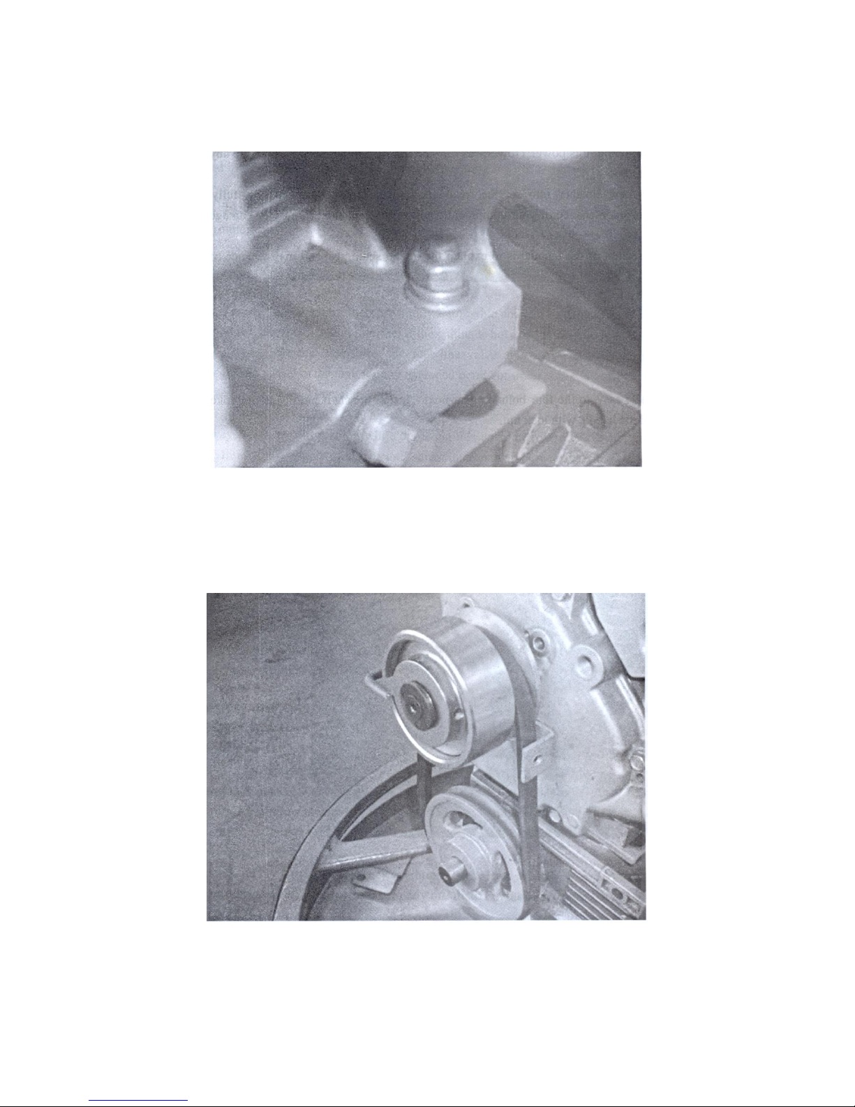
3) Install the drive belt.
Adjust the pulley to keep the clutch and pulley in one line.

9
4) Connect one stop wire leader to engine mounting bolt.
Another leader to engine stop connector.
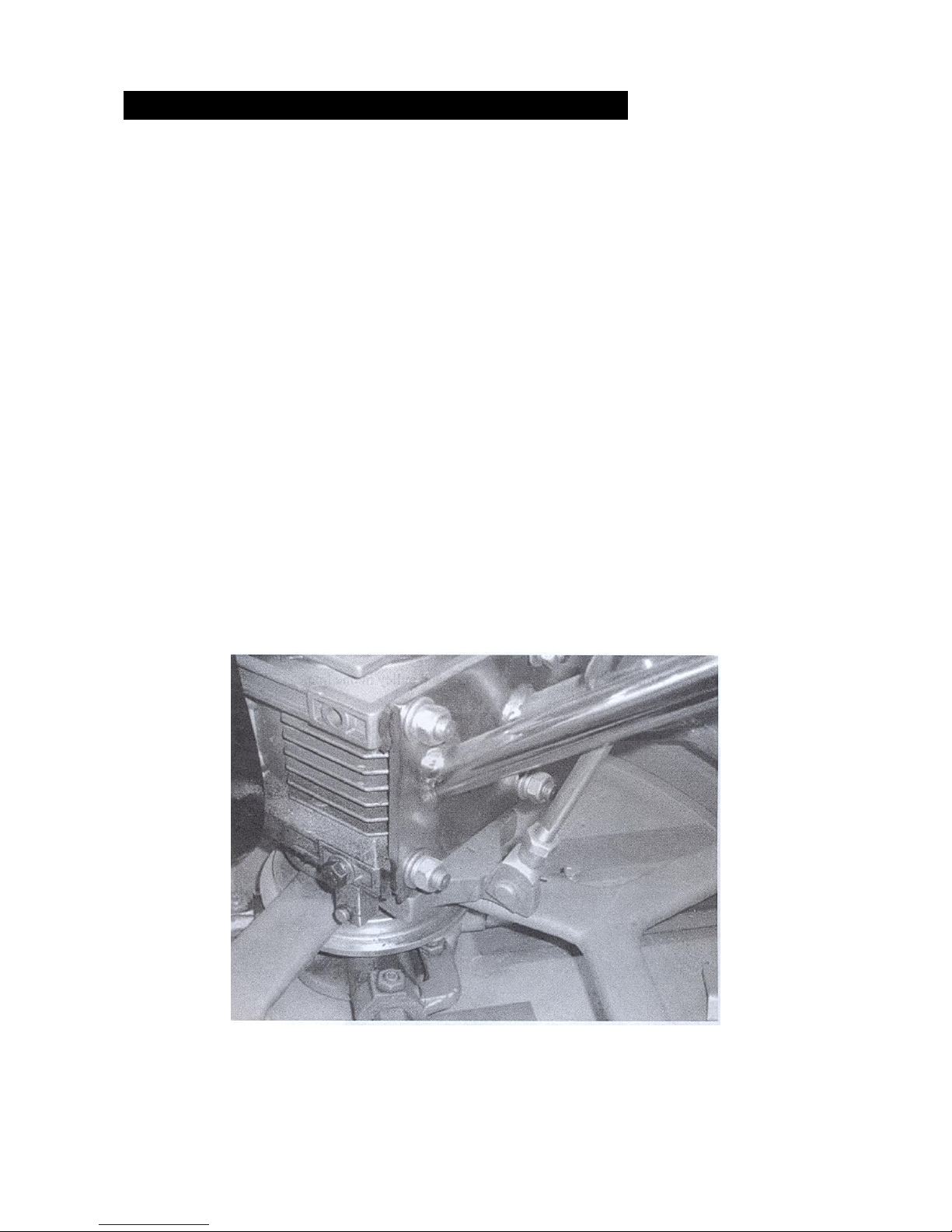
5) Connect throttle control wire to engine.
Set the throttle lever to the idle position by pushing it away from the operator’s position
towards the engine. Loosen the screw that crimps the throttle cable to allow free
movement of throttle cable.
Connect the throttle cable to the engine. Keep in mind there should be a piece of wire
installed on the machine to show you where to route the throttle cable. When connecting
the cable housing, make sure that no more than ¼ (6.4mm) of the cable housing protrudes
past the housing clamp on the engine.
Tighten the clamp on the throttle control, operator position of the handle.

10
Honda Engine
6) Inspect all the screw and lock nut which is safety tightened.
Operating
Always look behind you to avoid hazards before moving backwards
1. Engine key switch in “ON” position
2. Set throttle control level in idle position.
3. Grasp the control handle with left hand, right hand start the engine. Pull slowly on
starter rope until resistance is felt, then pull briskly to start the engine. If the engine
fails to start after several tries, consult the engine owner’s manual.
4. Get into the operator’s position behind the handle. With a secure foothold and a firm
grasp on the handless slowly increase the engine speed until the desired blades
speed is obtained.

11
5. Adjust the blade adjust wheel to make the blades according the work requirement.
Stop
1. Adjust engine speed to idle speed. Stop the engine.
2. In emergency situation, loosen the safety stop switch by your hand to stop the
engine.

12
General Instructions
Cleanup
NEVER allow concrete to harden on the power trowel.
Immediately after use, wash any concrete off your trowel with water. Be careful not to
spray water on the engine. An old paintbrush or broom may help loosen any concrete that
has started to burden.
Coat the blades and blades arms with diesel fuel after cleaning. This should help prevent
rusting and allow for easier cleanup in the future.
Maintenance service, adjustment and repair.
NOTE: See the engine manual supplied with your machine for appropriate engine.
Maintenance schedule
Daily (8-10 Hours)
Check the fluid levers in the engine and gearbox.
Weekly (50-60 Hours)
Re-lubrication arms, thrust collar and clutch. Replace the blades if necessary.
Check and clean or replace the engine air filter as necessary.
Monthly (100-200 Hours)
Remove, clean, reinstall and re-lubrication the arms, thrust collar and clutch.
Adjust the blade arms.
Yearly (200-2500 Hours)
Check and replace if necessary the arm bushings, thrust collar bushing, shaft seals and
belt.
Check pitch control cable for wear.

13
SERVICE PROCEDURES
Checking Belt Tension.
The first indication of belt wear is a reduced blade speed despite the engine running at full
speed.
Inspect belts often for signs of damage or excessive wear.
There is no method for manual adjustment of belt tension. Excessively worn belts must be
replaced.
There are some things to look for when checking to see if adjustment is necessary. Is the
machine wearing out blades unevenly (i.e. one blade is completely worn out while the
others look new)?
Does the machine have a perceptible rolling motion? Look at the machine while it is
running, do the guard rings “rock up and down” relative to the ground? These are some
indications that the blade pitch needs to be adjusted.
Changing a Blade
We recommend that all the blades be changed at the same time. The machine may
wobble or bounce if only some of the blades are changed at one time.
1. Place the machine on a flat, level surface. Adjust the blade pitch control to make
the blades as flat as possible. Note the blade orientation on the trowel arm.
2. Remove the bolts and lock washers on the washers on the trowel arm, then
remove the blade.
3. Scrape all concrete particles from the trowel arm.
4. Install the new blade, maintaining the proper orientation for direction of rotation.
5. Affix the bolts and lock washers.
6. Repeat steps 2-6 for all of the remaining blades.

14
Finishing Pan
L030001 - L030003 pan is a standard equipment

15
TROWEL FINISHER SERIES-----TROUBLESHOOTING
1. Engine running rough or not at all.
Kill switch off or malfunctioning? Make sure that the kill switch is on or replace
switch if necessary.
2. Other problems? Consult engine manufacture’s manual.
Safety kill switch not functioning.
Loose wire connections? Check wiring. Replace switch if necessary.
3. Bad contacts? Replace switch.
Clutch slipping or sluggish response to engine speed change.
4. Worn belts? Replace.
5. Dirty centrifugal clutch? Disassemble and clean the clutch.
6. Worn out centrifugal clutch? Replace entire clutch.
7. Hand clutch out of adjustment? Adjust as per instructions in maintenance section.
8. Worn hand clutch parts? Replace parts as necessary.

16
Spare parts – Handle

17
Spare parts – Circle’s protection

18
List of spare parts

19

20

21
CE C
ONFORMITY DECLARATION
Conformity Declaration CE
Conforms to the II A Attached, of the 2006/42 CE Directive
Conforms to the II Attached, of the 2000/14 CE Directive
The ISOPLAM S.r.l. company
With legal head office in E.Mattei, 4 31010 Coste di Maser (TV) Italy
DECLARES
Under its exclusive responsibility
That the machine
CONCRETE
POWER
TROWEL
Type
Serial number N.
L030001 - L030003
REVOLVING CIRCLE
_______
It is according with the conditions foreseen from the directives (and further
modifications)
2006 / 42 / CE
Concerning the rapprochement of the legi
slations of the member States
relative to the machines.
2014 / 30 / CE
Concerning the rapprochement of the legislations of the member States
relative to the electro-magnetic compatibility.
2014 / 35 / CE
2000 / 14 / CE
Concerning the rapprochement
of the legislations of the member States
relative to the electric material assigned to be used within some limits of
voltage.
Ambient acoustic emission of machines and equipment for the open
work.
Level of sonorous powering of measured similar machine: 102 dBA (petrol version) – 74 dBA (electrical version)
Level of sonorous guaranteed powering for the equipment: 102 dBA (petrol version) – 74 dBA (electrical version)
(D.Lgs. n.262/2002)
Urbino, Signature
The Representative Legal

22
PROHIBITION OF PUTTING IN SERVICE
It cannot be put in service, after to have undergone the constructive modifications or integrations of other
components not falling within the ordinary or extraordinary maintenance, without that it is still declared
according to the requirements of the directives: 2006/42/CE, 2014/30/CE, 2014/35/CE and 2000/14/CE to
other directives of reference and to the norms in force.
Date,
The Owner
SECURITY NORMS
The machine has been realized in according with the security norms under indicated:
UNI EN ISO 12100-1
Security of the machinery - Fundamental concepts, general principles of
planning. – (Part 1: Terminology of base, methodology).
UNI EN ISO 12100-2
Security of the machinery - Fundamental concepts, general principles of
planning. – (Part 2: Technical principles).
UNI EN ISO 13857:2008
Security of the machinery – Distance of security to prevent the achieving of
dangerous areas with superior limbs.
UNI EN 953:2009
Security of the machinery – Shelters – general requirements for the planning
and the building of fixed and movable shelters.
CEI EN 60204-1
Security of the machinery – Electric equipment of machines (Part I: general
Norms)

23
Conformity Declaration of the European Norms
ENCLOSURE: List of the security essential requirements which the machine is
accordance
The machine is accordance with all security requirements estimated and listed as follows:
01 GENERAL PRECAUTIONS: Improper use of the machine; user position; materials
and products; Illumination.
02 TRANSPORT: The machine planning in order to the transport.
03 INSTALLATION: Security and dependability; control devices; starting; stop devices;
failure of the circuit of energy power unit; due risks at extreme temperatures; due
risks at the noise.
04 MECHANICAL: Stability; break risks during the working; due risks of objects
protection; due risks to surfaces, edges and angles; due risks at the vibrations; due
risks at the accidents and explosions; due risks to the noise.
05 PROTECTIONS: General requirements; risks of the fixed protections; risks of
duration.
06 THE ENERGY SOURCES: Due risks at energy type.
07 MAINTENANCE AND MOUNTING: Due risks to the mounting mistakes; machine
maintenance; user intervention.
08 POWDERS AND GAS EMISSIONS: Due risks to the powders or gas emission.
09 CONTROL PLACE: Limits to the machine use; due risk to the visibility; risk to stay
trapped in the machine.
10 RISKS AND RESIDUALS: Signalling and warning on the user manual; use of
suitable nameplates and adhesives.
The lacking necessary security requirements that are listed in the Norm 2006/42/CE -
Enclosure 1, aren’t connected with constructive and functional principles of this machine.

24
ISOPLAM S.r.l.
Via E. Mattei, 4 31010 COSTE DI MASER (TV) ITALY
Tel. Export: 039 0423 925023 WEB site:
www.isoplam.it e-Mails: info@isoplam.it
 Loading...