

ISON IS-RG528 Series Web Configuration Tool Manual

IS-RG528 Series
28-Port Industrial Ethernet Managed Switch
Web Configuration Tool Guide
Version Number: v1.0
Issue: 1.1r1, June 2015

2
[CONTENTS]
1. Introductions .................................................................................................................................... 4
1.1 System Description ................................................................................................................... 4
1.2 Using the Web Interface ........................................................................................................... 4
1.2.1 Web Browser Support .................................................................................................. 4
1.2.2 Navigation .................................................................................................................... 5
1.2.3 Title Bar Icons............................................................................................................... 5
1.2.4 Ending a Session ........................................................................................................... 6
1.3 Using the Online Help............................................................................................................... 6
2. Using the Web .................................................................................................................................. 7
2.1 Login ......................................................................................................................................... 7
2.2 Tree View ................................................................................................................................. 8
2.2.1 Configuration Menu ..................................................................................................... 8
2.2.2 Monitor Menu .............................................................................................................. 8
2.2.3 Maintenance Menu ...................................................................................................... 9
2.3 Configuration .......................................................................................................................... 10
2.3.1 Link Aggregation ......................................................................................................... 10
2.3.2 802.1x Authentication ................................................................................................ 11
2.3.3 Interface VLAN ........................................................................................................... 14
2.3.4 Static Route ................................................................................................................ 15
2.3.5 Port Configuration ...................................................................................................... 16
2.3.6 VLAN ........................................................................................................................... 27
2.3.7 MAC Learning & Forwarding ...................................................................................... 33
2.3.8 Spanning Tree Protocol (STP) ..................................................................................... 34
2.3.9 Policer ......................................................................................................................... 46
2.3.10 ACL............................................................................................................................ 50
2.3.11 Shaper ...................................................................................................................... 56
2.3.12 Queue & Scheduler .................................................................................................. 58
2.3.13 Storm Control ........................................................................................................... 61
2.3.14 IGMP ......................................................................................................................... 67
2.4 Status ...................................................................................................錯誤! 尚未定義書籤。
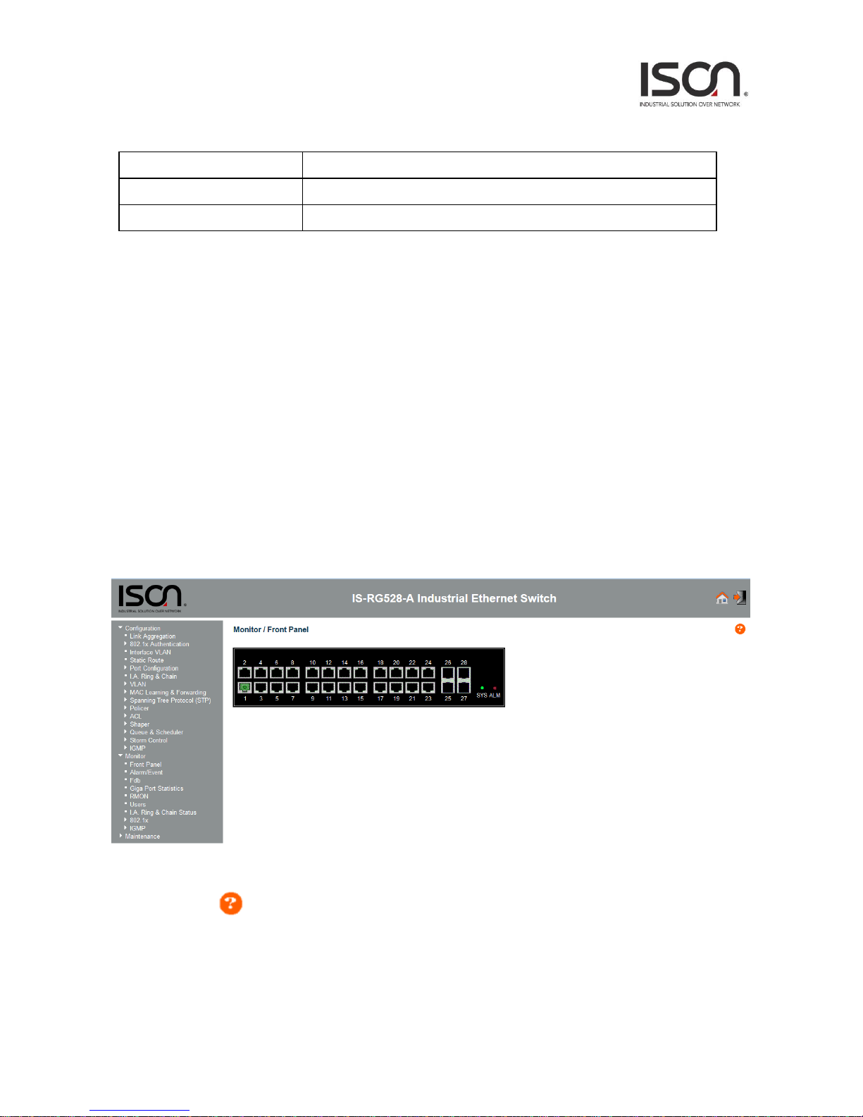
2.4.1 Front Panel ................................................................................................................. 77
2.4.2 Alarm/Event ............................................................................................................... 83

3
2.4.3 Fdb .............................................................................................................................. 85
2.4.4 Giga Port Statistics...................................................................................................... 86
2.4.5 RMON ......................................................................................................................... 89
2.4.6 Users ........................................................................................................................... 91
2.4.7 I.A. Ring & Chain Status .............................................................................................. 92
2.4.8 802.1x ......................................................................................................................... 93
2.4.9 IGMP ........................................................................................................................... 98
2.5 System .................................................................................................................................. 100
2.5.1 Restart ...................................................................................................................... 100
2.5.2 Save & Restore ......................................................................................................... 101
2.5.3 Firmware .................................................................................................................. 103
2.5.4 Alarm Profile ............................................................................................................ 104
2.5.5 CLI Options ............................................................................................................... 105
2.5.6 HTTP (HTTPS) ........................................................................................................... 106
2.5.7 SLL ............................................................................................................................ 107
2.5.8 SNTP ......................................................................................................................... 108
2.5.9 Syslog ........................................................................................................................ 109
2.5.10 User Administration ............................................................................................... 110
2.5.11 SNMP ...................................................................................................................... 112

4
1. Introductions
1.1 System Description
IS-RG528 Series 28-port Managed switches deliver high quality, wide operating temperature range,
extended power input range, IP-30 design, and advanced VLAN & QoS features. It’s ideal for harsh
environments and mission critical applications.
IS-RG528 Series Managed switches provides enterprise-class networking features to fulfill the
needs of large network infrastructure and extreme environments.
IS-RG528 Series Managed switches ease the effort to build a network infrastructure which offers a
reliable, well managed and good QoS networking for any business requiring continuous and
well-protected services in industrial environments. With the features such as I.A. Ring & Chain,
Ethernet OAM, IEEE 1588v2 / Sync-E and QoS, customers can ensure their network is qualified to
deliver any real-time and high quality applications.
1.2 Using the Web Interface
The object of this document “IS-RG528 Series Web Configuration Tool Guide” is to address the web
feature, design layout and descript how to use the web interface.
1.2.1 Web Browser Support
IE 7 (or newer version) with the following default settings is recommended:
Language script
Latin based
Web page font
Times New Roman
Plain text font
Courier New
Encoding
Unicode (UTF-8)
Text size
Medium
Firefox with the following default settings is recommended:
Web page font
Times New Roman
Encoding
Unicode (UTF-8)
Text size
16
5
Google Chrome with the following default settings is recommended:
Web page font
Times New Roman
Encoding
Unicode (UTF-8)
Text size
Medium
1.2.2 Navigation
All main screens of the web interface can be reached by clicking on hyperlinks in the four menu
boxes on the left side of the screen:
Status - Display statistics, status, and contents of memory.
Configuration - Configure the system, interfaces, and filters.
System - Display system information, download firmware, back up configurations, and modify
users.
You can find the detailed information in section 2.2 Tree View.
1.2.3 Title Bar Icons
Help Button
For more information about any screen, click on the Help button on the screen.
Help information is displayed in the same window.

6
Save Button
If any unsaved change has been made to the configuration (by you during this or a prior session, or
by any other administrator using the web interface or the Command Line Interface), a Save icon
appears in the title line. To save the running configuration to the startup configuration:
1. Click on the Save icon. The System/Save and Restore screen appears.
2. Click on Submit next to Data Control Action drop-down list on top of System/Save and
Restore screen.
1.2.4 Ending a Session
To end a session, close your web browser. This prevents an unauthorized user from accessing the
system using your user name and password.
1.3 Using the Online Help
Each screen has a Help button that invokes a page of information relevant to the particular
screen. The Help is displayed in a new window.
Each web page of Configuration/Status/System functions has a corresponding help page.
7
2. Using the Web
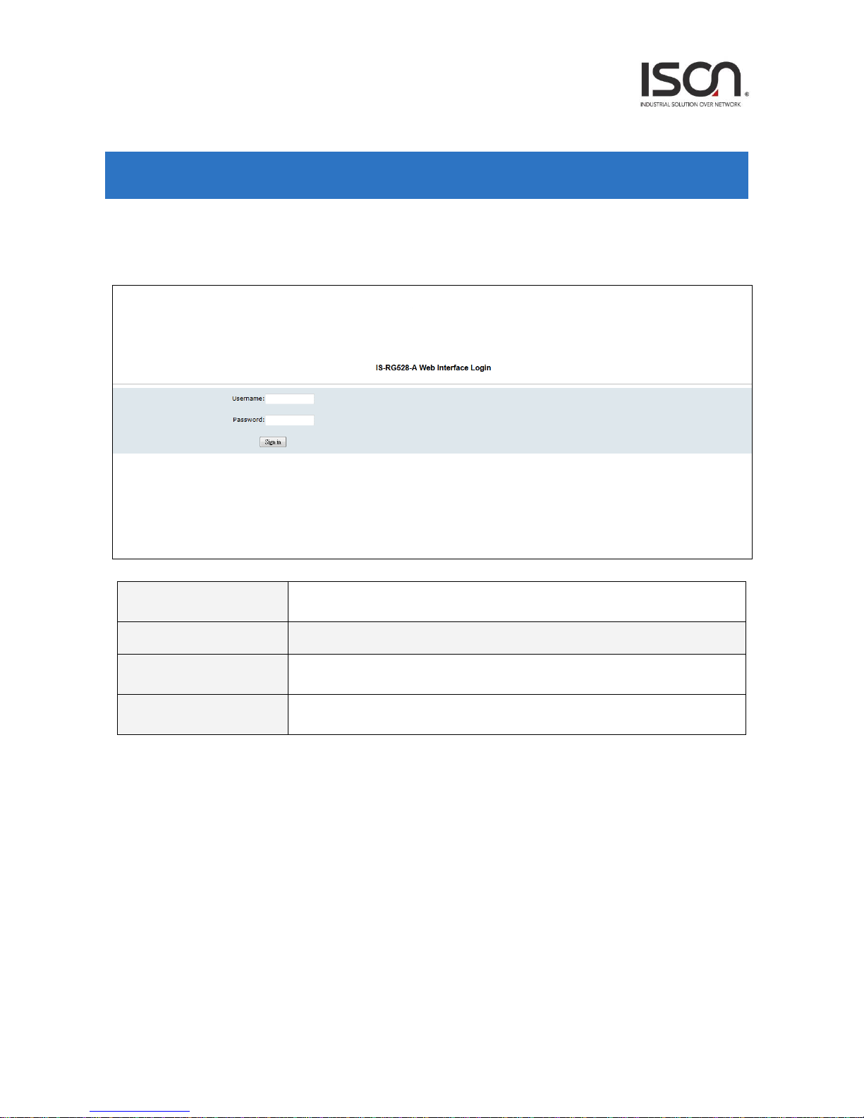
2.1 Login
Operation
1. Fill Username and Password
2. Click “Sign in”
Field
Description
Username
Login user name. The maximum length is 32.
Default: admin
Password
Login user password. The maximum length is 32.
Default: admin
8
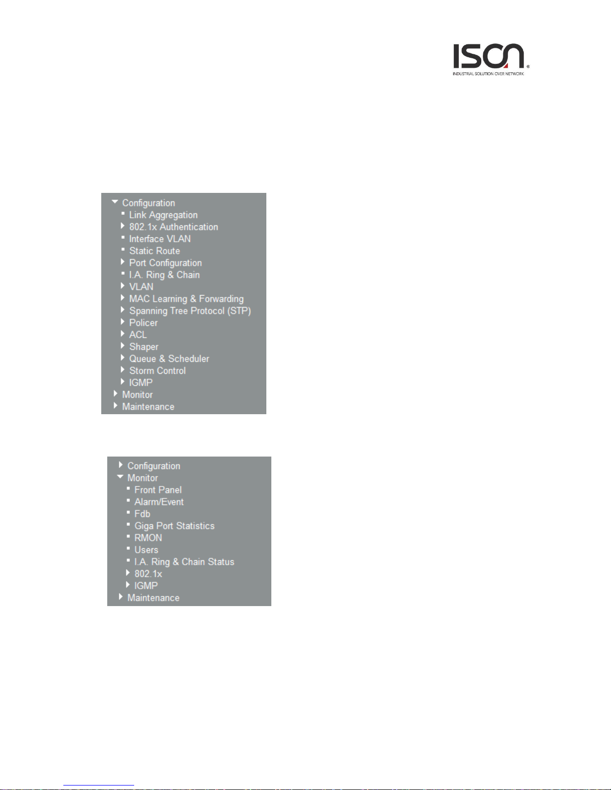
2.2 Tree View
The tree view is a menu of the web. It offers user quickly to get the page for expected data or
configuration.
2.2.1 Configuration Menu
2.2.2 Monitor Menu

9
2.2.3 Maintenance Menu
10
2.3 Configuration
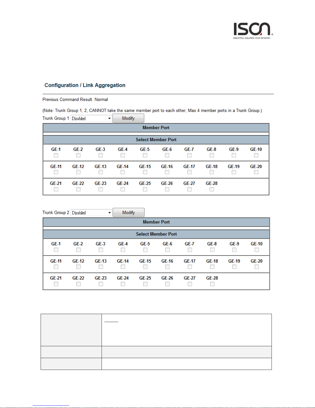
2.3.1 Link Aggregation
Operation
Modify:
1. Select port with check box from GE-1 ~ GE-xx (xx = 10~28).
2. Click Modify button.
Field
Description
Trunk Group
Trunk Group number.
11
Note:
Trunk Group 1 & 2 CANNOT take the member port that is
already assigned to another Trunk Group; Max 4 member ports in a Trunk Group.
Otherwise, the modification would be failed.
Member Port
Display current member port of Trunk Group.
Mode
To enable/disable Link Aggregation for Trunk Group.
GE-1~GE-xx (xx=10~28)
To select member ports for Trunk Group. If Link Aggregation mode is disabled,
then the member port would be cleared, that represents no member port is assigned
to Trunk Group.
2.3.2 802.1x Authentication
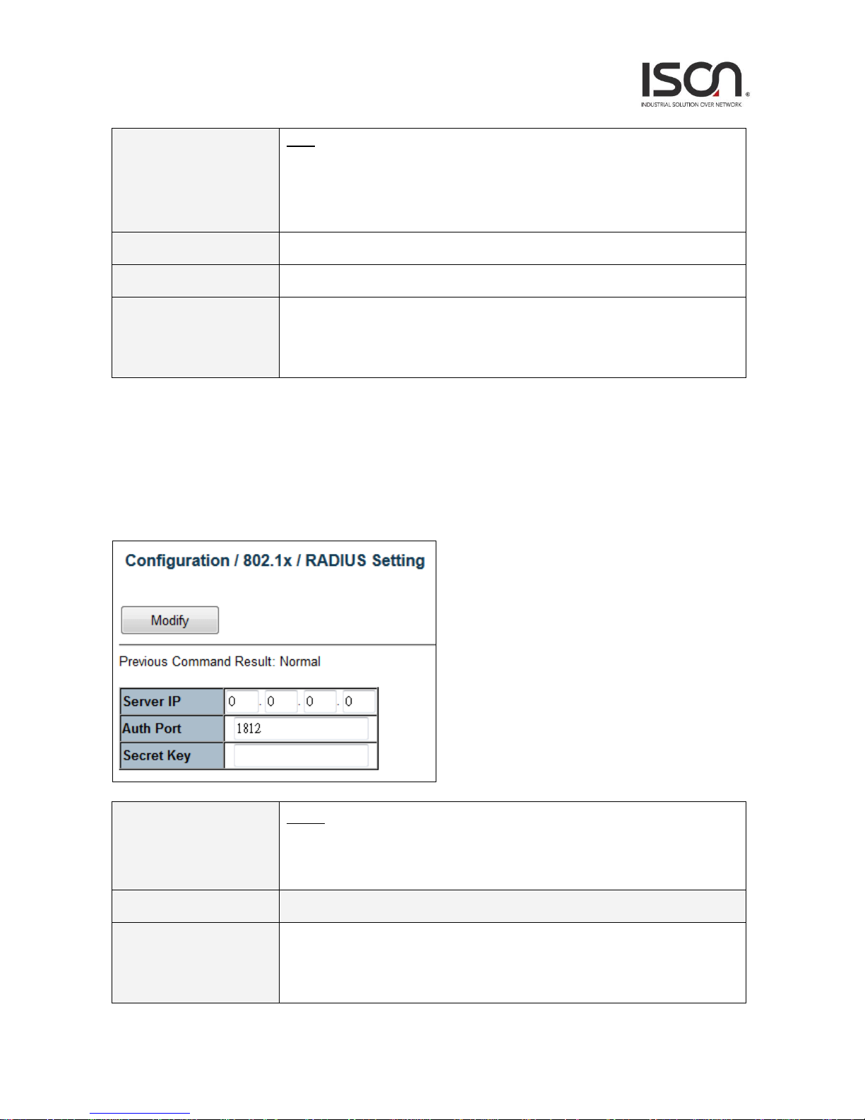
2.3.2.1 RADIUS Setting
Operation
Modify:
1. Modify Server IP, Authentication Port and Secret Key fields.
2. Click "Modify" button to apply change.
Field
Description
Server IP
The IP address of RADIUS server.
Allow IPv4 address. 0.0.0.0 means disable RADIUS.
Default is 0.0.0.0.
12
Auth Port
The UDP port of RADIUS server for authentication.
Range 1~65535.
Default is 1812.
Secret Key
The key to be used between RADIUS server and Authenticator.
Range 0~16 chars.
Default is empty string.
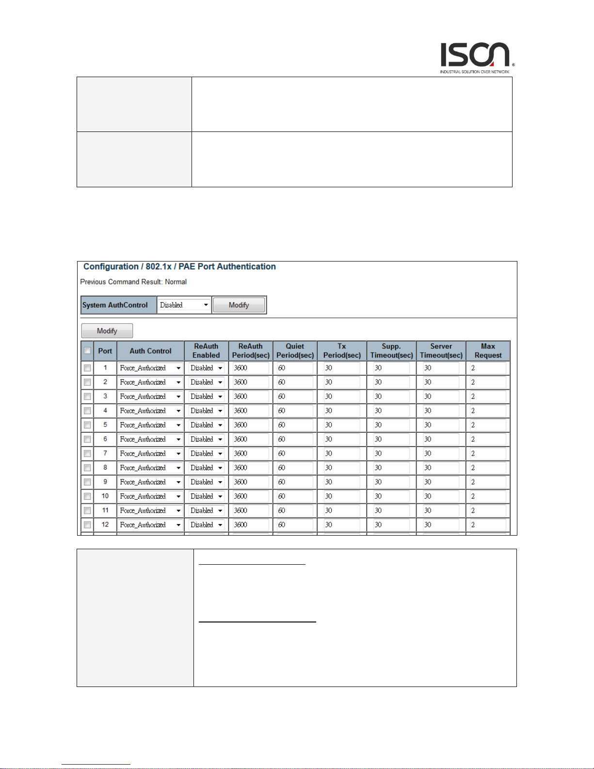
2.3.2.2 PAE Port Authentication
Operation
Modify System Auth. Control:
1. Select System Auth. Control.
2. Click "Modify" button to apply change.
Modify PAE Port Authentication:
1. Update below fields.
2. Check up the port(s) to be changed.
Click "Modify" button to modify PAE Port Authentication options.

13
Field
Description
System AuthControl
Enable/Disable system 802.1x authentication function.
Default value is Disabled.
Port
PAE port: 1 ~ MAX Number of Port.
Auth Control
The authentication type of PAE port.
Allow Force_Unauthorized/Force_Authorized/Auto.
Default is Force_Authorized.
ReAuth Enabled
Enable/Disable re-authenticate of PAE port.
Default is Disable.
ReAuth Period
The period of re-authenticant of PAE port.
Range 1~3600 sec.
Default is 3600 sec.
Quiet Period
The quiet period of PAE port.
Range 1~255 sec.
Default is 60 sec.
Tx Period
The timeout of authenticator waiting for EAP-Response/ Identity from supplication of
PAE port.
Range 1~255 sec.
Default is 30 sec.
Supp. Timeout
The timeout of authenticator wait for EAP-Response (exclude EAP-Request/Identify)
after sending EAP-Request.
Range 1~255 sec.
Default is 30 sec.
Server Timeout
The timeout time of Authenticator wait Access-Challenge/ Access-Accept/
Access-Reject after sending Access-Request.
Range 1~255 sec.
Default is 30 sec.
Max Request
The max times of backend Authenticator send EAP-Request to supplicant before
restarting the authentication process.
Range 1~10.
Default is 2.
14
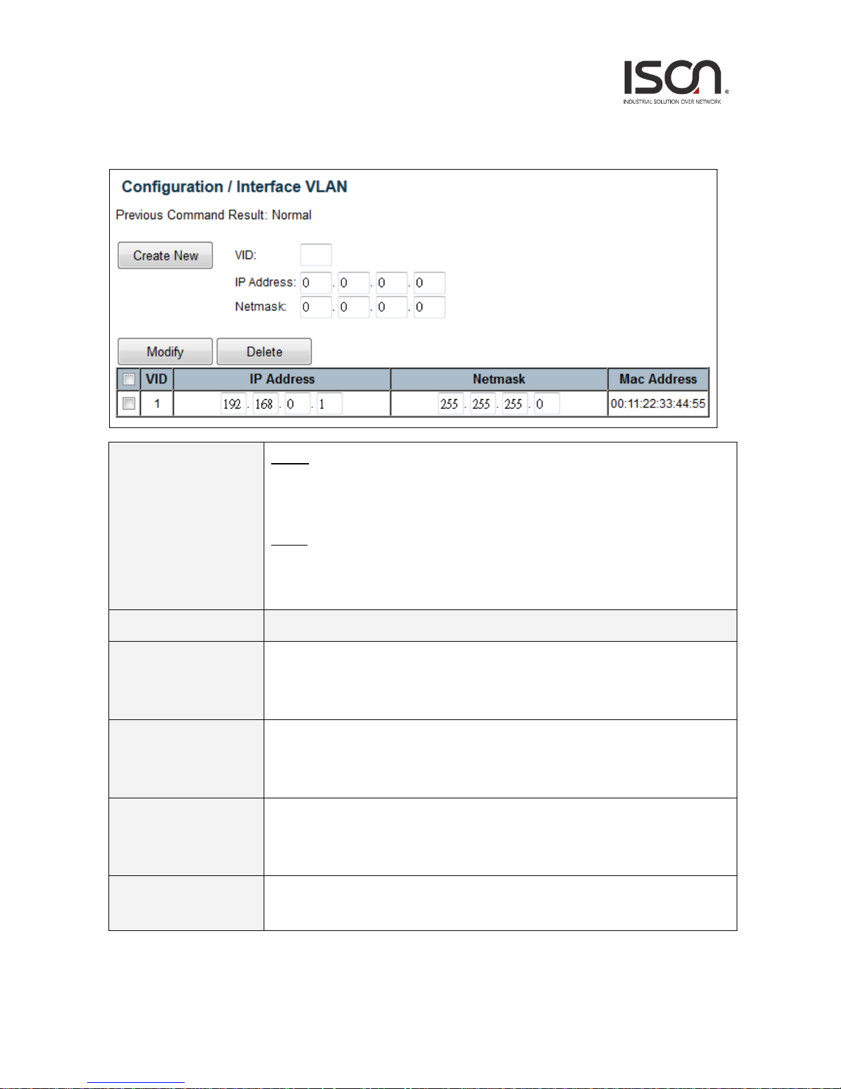
2.3.3 Interface VLAN
Operation
Create:
1. Fill VID, IP Address and Netmask
2. Click "Create New" button to create Interface VLAN.
Delete:
1. Multi-select a row data in Interface VLAN table.
2. Click "Delete" button to delete Interface VLAN.
Field
Description
VID
The identity for the RIP Interface.
Range 1~4094.
1st RIP interface VLAN always exist for VLAN 1. (Only support set can't be deleted)
IP Address
IP address for the vlan interface.
Range 0~255.
Default value is 0.
Netmask
Network subnet mask for the VLAN interface.
Range 0~255.
Default value is 0.
Mac Address
MAC address for the VLAN interface.
Readonly.
15
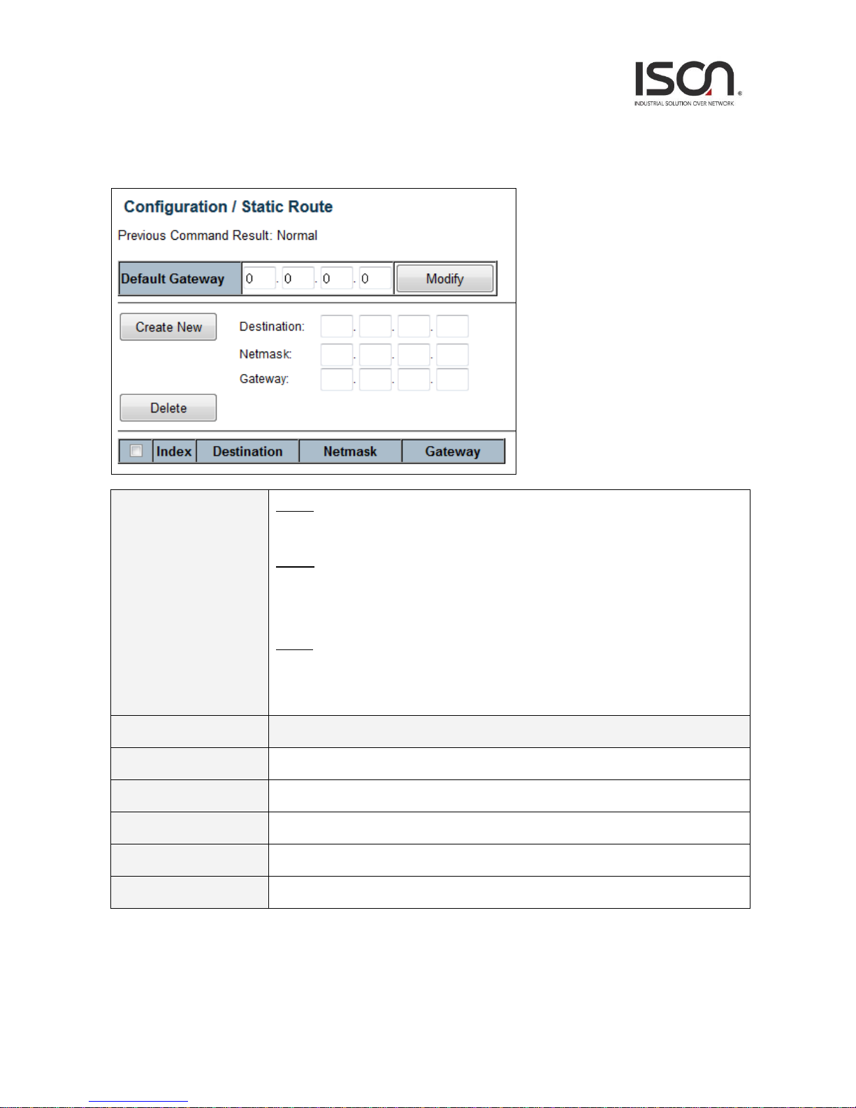
2.3.4 Static Route
Operation
Modify:
Click "Modify" button to apply new gateway.
Create:
1. Fill Destination, Netmask and Gateway.
2. Click "Create New" button to create one static route.
Delete:
1. Select static route entry(s).
2. Click "Delete" button to delete selection.
Field
Description
Default Gateway
Input default gateway IP address for management and Layer3 VLAN interface routing
Destination
Destination network address of static route.
Netmask
Network subnet mask for the route.
Gateway
Next hop IP address for the destination network.
Index
The index of the static route.

16
2.3.5 Port Configuration
2.3.5.1 Bridge Port
Operation
Modify:
1. Enter or select row by checking up check box.
2. Modify the configuration
3. Press “Modify” button to apply modification.
Refresh:
1. Click “Refresh” button to get current data.
Field
Description
Port
Bridge port number
17
PVID
Value: 1~4094.
Default value is 1.
Default
Priority
Default Priority value: 0~7.
Default is 0.
Accept Frame Type
Type: All/ OnlyVlanTagged/ Only Untagged.
Default is All.
Max MAC Limit
Range: Enabled/ Disabled.
Default is Disabled.
Max MAC
Range: 0~32.
Default is 8.
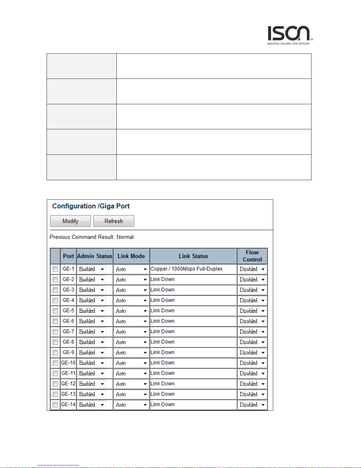
2.3.5.2 Giga Port

18
Operation
Modify:
1. Select a row item to selected
2. Set or select the following fields.
3. Click "Modify" button to modify.
Field
Description
Port
GE-1~ MAX Number of Port.
Admin Status
Enabled/Disabled, default=Enabled.
Link Mode
Configuration for Link Mode: Auto (default is Auto)
10Mbps Half/Full Duplex
100Mbps Half/Full Duplex
1000Mbps Full Duplex
2500Mbps Full Duplex (only in some model)
Link Status
Display Link type and speed
Possible Type: Copper/ SFP
Possible Status:
10Mbps Half-Duplex or Full-Duplex
100Mbps Half-Duplex or Full-Duplex
1000Mbps Full-Duplex
2500Mbps Full-Duplex (only in some model)
Copper/ SFP Priority
Only some model supports Copper/SFP combo port, default is SFP first.
Flow Control
Range: Enabled/Disabled, default=Disabled.

19
2.3.5.3 Port Isolation
Port Isolation-Modify
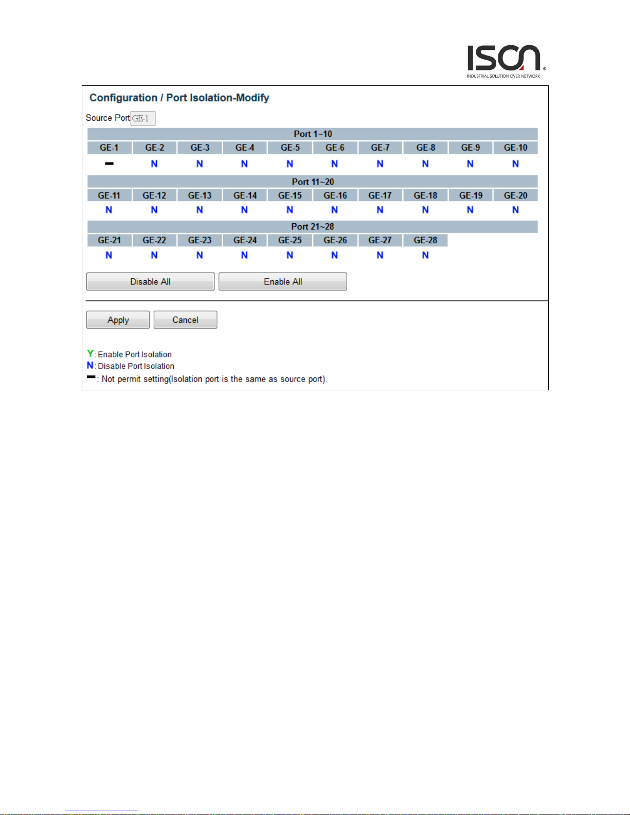
20

21
Operation
Modify:
Click “Modify” button to open modification page.
Port Isolation - Modify:
1. Click “Disable All”, ”Enable All” or click on (Y/N/-) to change isolation setting by port.
2. Click “Apply” to apply change or Press “Cancel” to cancel and go back to main page
of Isolation.
Field
Description
Source Port
GE-1 ~ MAX Number of Port.
Isolation Port
Option: Y/ N/ -.
Y: Isolation is true
N: Isolation is false
-: Not permit setting (Isolation port is the same as source port)
Disable All
Disable Isolation to all ports
Enable All
Enable Isolation to all ports
Apply
Apply setting data.
Cancel
Cancel setting data.
22
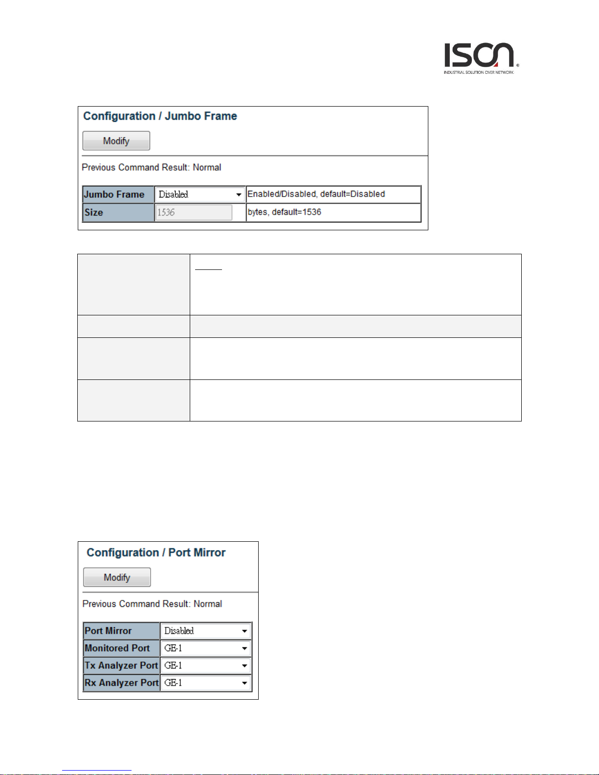
2.3.5.4. Jumbo Frame
2.3.5.5 Port Mirror
Operation
Modify:
1. Modify the configuration.
2. Click “Modify” button to apply change.
Field
Description
Jumbo Frame
Option: Enabled/ Disabled,
Default is Disabled.
Size
Range: 1536~9000 bytes,
Default is 1536 bytes.
23
Operation
Modify:
1. Modify the configuration
2. Click “Modify” button to apply change
Field
Description
Port Mirror
Enable/Disable Port Mirror function, default is Disabled.
Monitored Port
Value range is GE-1 ~ Port MAX Number, default is GE-1.
Port to be monitored.
Tx Analyzer Port
Value range is GE-1 ~ Port MAX Number, default is GE-1.
It monitors 'out' packet of monitored port.
Rx Analyzer Port
Value range is GE-1 ~ Port MAX Number, default is GE-1.
It monitors 'in' packet of monitored port.
24
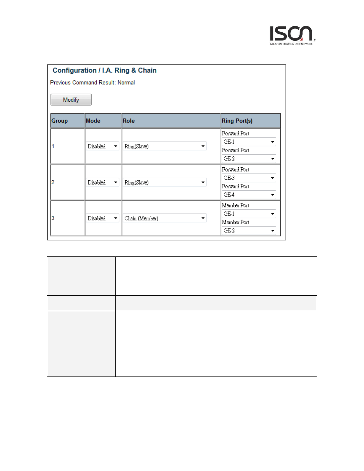
2.3.5.6 I.A. Ring & Chain
Operation
Modify:
1. Modify the configuration
Press “Modify” button to apply change.
Field
Description
Group
The group index. This parameter is used for easy identifying the ring when user
configure it.
Group 1 - this group supports configuration of ring.
Group 2 - this group supports configuration of ring, coupling and dual-homing.
Group 3 - this group supports configuration of chain and balancing-chain.

25
Mode
Enable Ring on the specific group.
# When Group 1 or 2 is enabled:
All configuration of Group 3 will be reset to default.
Group 3 all configuration options will be locked.
# To configure Group 3:
Both Group1 and 2 should be disabled first.
When Group 3 is enabled, all configuration of Group1 and 2 will be reset to
default.
Group 1 and 2 all configuration options will be locked.
Role
Configure the Ring group on this switch as specific role.
# Group 1 - support option of ring-master and ring-slave.
Ring - it could be master or slave.
# Group 2 - support configuration of the ring, coupling and dual-homing.
Ring - it could be master or slave.
Coupling - it could be primary or backup.
Dual-Homing
# Group 3 - support configuration of the chain and balancing-chain.
Chain - it could be head, tail or member.
Balancing Chain - it could be central-block, terminal-1/2 or member.
Note 1 - Group 1 must be enabled before enable Group 2 to coupling.
Note 2 - When Group 1 or 2 is enabled, the configuration of Group 3 will be
disabled.
Note 3 - When Group 3 is enabled, the configuration of Group 1 and 2 will be
disabled.

26
Ring Port(s)
Selecting ring port(s).
Each ring port must be unique, CANNOT be configured in different groups; 2 ring
ports between ring/chain CANNOT be the same.
# When role is ring/master:
One ring port is forward port and another is block port.
The block port is redundant port; it is blocking port in normal state.
# When role is ring/slave:
Both ring ports are forward port.
# When role is coupling/primary:
Only need one ring port named primary port.
# When role is coupling/backup:
Only need one ring port named backup port.
This backup port is redundant port; it is blocking port in normal state.
# When role is dual-homing:
One ring port is primary port and another is backup port.
This backup port is redundant port; it is blocking port in normal state.
# When role is chain/head:
One ring port is member port and another is head port.
Both ring ports are forwarding port in normal state.
# When role is chain/tail:
One ring port is member port and another is tail port.
The tail port is redundant port; it is blocking port in normal state.
# When role is chain/member:
Both ring ports are member port.
Both ring ports are forwarding port in normal state.
# When role is balancing-chain/central-block:
One ring port is member port and another is block port.
The block port is redundant port; it is blocking port in normal state.
# When role is balancing-chain/terminal-1/2:
One ring port is member port and another is terminal port.
Both ring ports are forwarding port in normal state.
# When role is balancing-chain/member:
Both ring ports are member port.
Both ring ports are forwarding port in normal state.
27
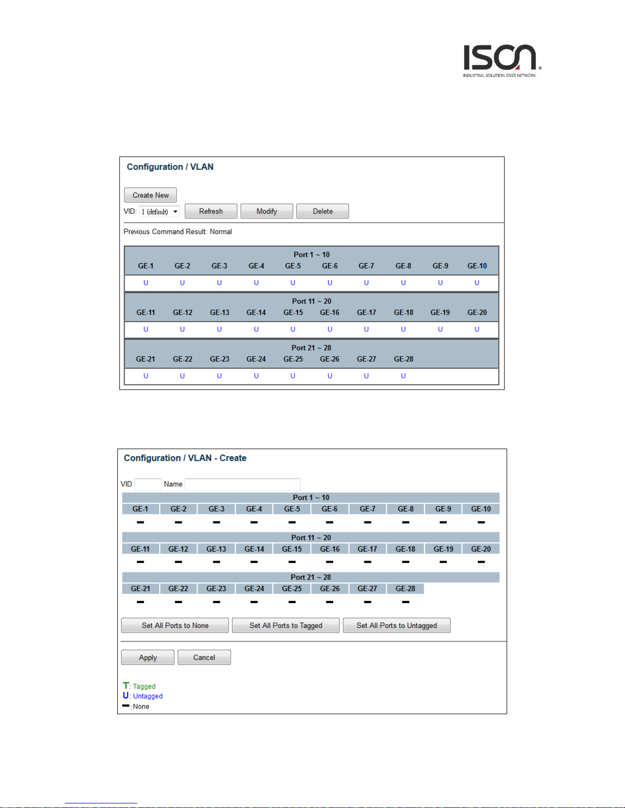
2.3.6 VLAN
2.3.6.1 Static VLAN
Create New VLAN
28
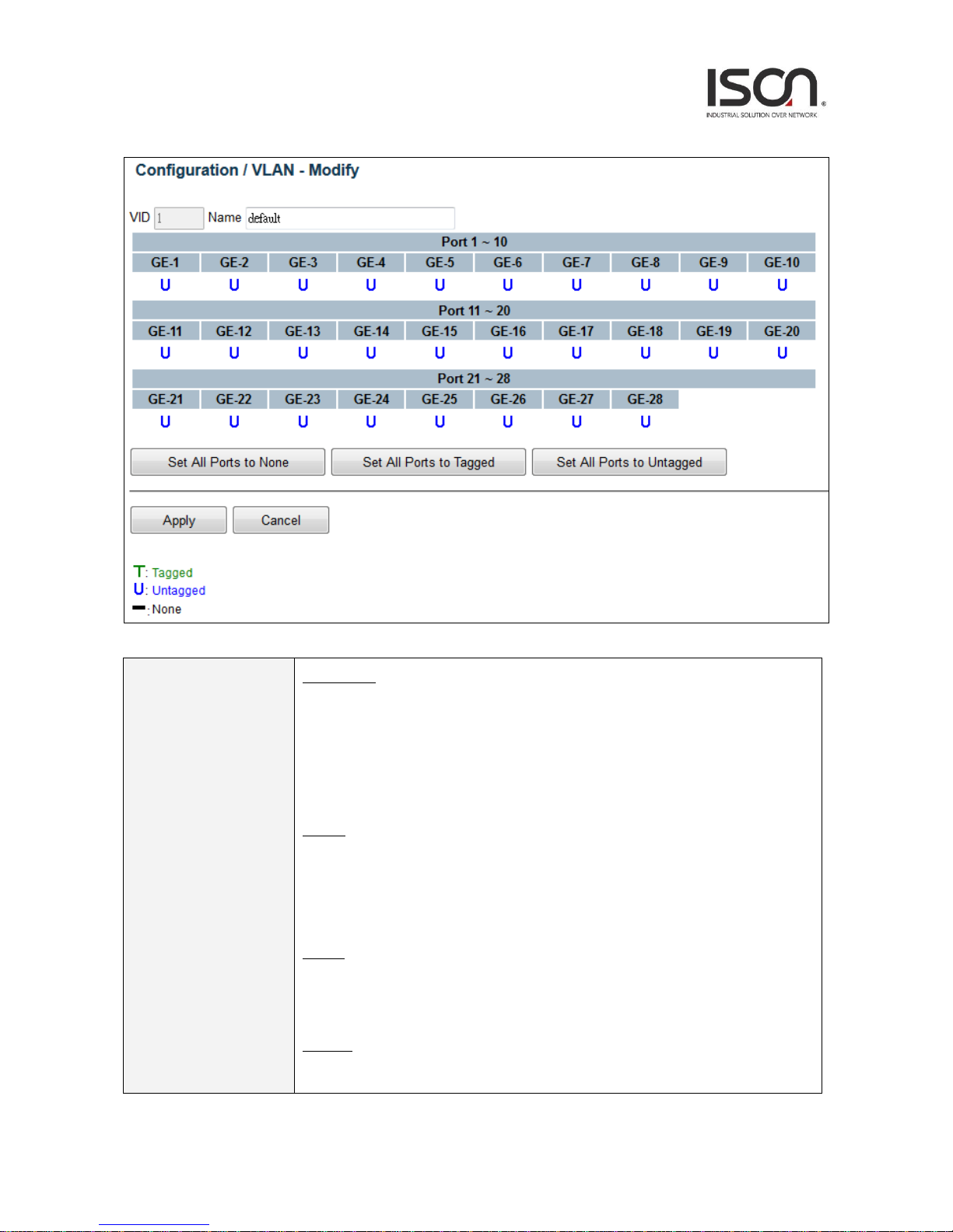
Modify VLAN
Operation
Create New:
1. Click “Create New” button to open “Create New” page.
2. Set VID and Name.
3. Click fields to change status.
4. Click “Apply” button to create, or click “Cancel” button to cancel.
Modify:
1. Click “Modify” button to open “Modify” page.
2. Modify Name.
3. Click “Apply” button to modify, click “Cancel” button to cancel.
Delete:
1. Choice VLANs checkbox to select.
2. Click “Delete” to delete all selected VLANs.
Refresh:
1. Click “Refresh” button to get current data.

29
Field
Description
VID
Value: 1~4094.
Default value is 1.
Name
Range:0~32 characters
Tagged
Range: T/ U/ -.
T: Tagged
U: Untagged
-: None (not join this VLAN)
Set All Ports to None
Set all ports to None (no port join this VLAN)
Set All Ports to Tagged
Set all ports join the VLAN as Tagged.
Set All Ports to
Untagged
Set all ports join the VLAN as Untagged.
2.3.6.2 Protocol Based VLAN
30
Operation
Create New:
1. Click "Create New" button to Create New page.
2. Set Port and Ether Type, input SVLAN and S-Prio.
3. Click Create New button. (Max entry: 10.)
Delete:
1. Select Index with check box.
Click "Delete" button to delete data.
Field
Description
Index
Index 1~10.
Port
Protocol-base VLAN config port number, Port range:1 ~ MAX Number of Port.
Ether Type
Select Ether Type:
1. PPPoE Discovery Stage (0x8863).
2. PPPoE Session Stage (0x8864).
3. Internet Protocol (0x0800).
4. Address Resolution Protocol (ARP) (0x0806).
5. Others (input ether type), Range 0000~FFFF.
SVLAN
Service VLAN ID, Range 1 ~ 4094
S-Prio
CoS of SVLAN: 0~7, 8:reserve
 Loading...