

ISOMAG ML 252 Installation Manual

OPERATING AND INSTALLATION MANUAL
CONVERTER
ML 252

2
252_EN_IS_1_3_00.doc
q Introduction _______________________________________________________________________________________pag.3
§ Symbols Used on the manual ____________________________________________________________________pag.3
§ Overall dimensions _____________________________________________________________________________pag.4
q Technical characteristics of converter ______________________________________________________________pag.5
§ Electrical characteristics_________________________________________________________________________pag.5
§ Environmental conditions of use__________________________________________________________________pag.5
§ Operative temperature __________________________________________________________________________pag.5
§ Measure and consumption ______________________________________________________________________pag.6
q Electrical connections ______________________________________________________________________________pag.7
§ Output on/off 50Hz _____________________________________________________________________________pag.7
q Start up and maintenance of the instruments_______________________________________________________pag.8
§ Device switch on ______________________________________________________________________________pag.9
§ Batteries power supply __________________________________________________________________________pag.9
q How to access at the instrument functions ________________________________________________________ pag.10
§ User interface ________________________________________________________________________________ pag.10
§ Access codes _________________________________________________________________________________ pag.10
§ Converter visualisation pages __________________________________________________________________ pag.11
§ Flags interpretation and led _____________________________________________________________________ pag.12
§ Converter key board ___________________________________________________________________________ pag.13
§ Functions description __________________________________________________________________________ pag.14
§ Access to the configuration menu _______________________________________________________________ pag.17
q Programming functions ___________________________________________________________________________ pag.19
§ Functions description __________________________________________________________________________ pag.19
q Alarm messages __________________________________________________________________________________ pag.24
§ Causes and action to be taken __________________________________________________________________ pag.24
§ Anomalies codes ______________________________________________________________________________ pag.24
APPENDIX 1
Batteries substitution ______________________________________________________________________________________ pag.25
INDEX
3
252_EN_IS_1_3_00.doc
Symbols Used on the manual
This manual is integral part of the product. Read carefully the instructions contained it
since it contains important indications for a safe of use and maintenance.
Technic
al information and relative products in this manual could undergo modifications
without any previous notice.
The flow meter must be used for what it has been built for. The improper use, possible
tampering of the instrument or parts of it and substitutions
of any not original
components, makes the warranty to decay automatically.
The manufacturer is considered responsible only if the instrument in used in his original
configuration.
The reproduction of the present manual and of possible software supplied
with the instrument it’s strictly forbidden
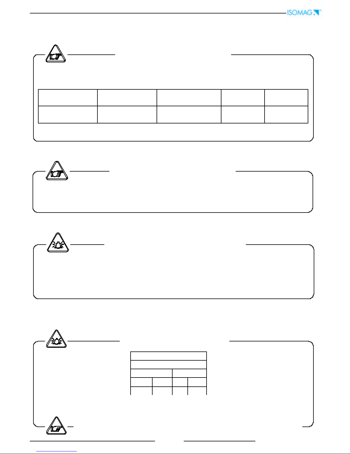
ATTENTION
WARNING
PRECAUTIONS
DANGER ELECTRIC SHOCK
INTRODUCTION
4
252_EN_IS_1_3_00.doc
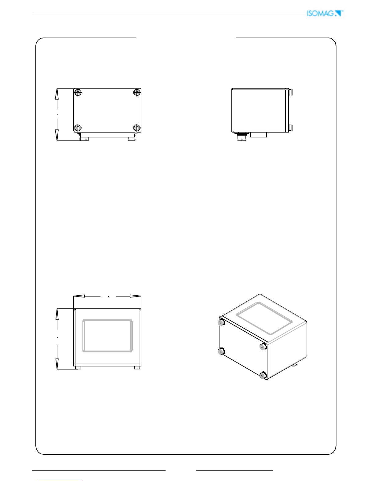
125
112 97
OVERALL DIMENSIONS
5
252_EN_IS_1_3_00.doc
TECHNICAL CHARACTERISTICS
OPERATING TEMPERATURE
CONVERTER
Ambient Temp.
Min. Max
°C °F °C °F
-10* -14* 50 122
ELECTRIC CHARACTERISTICS
Classification of the instrument: class I, IP 67, category of installation II
Power supply
version
Power supply
voltage
Power supply
frequency
Max
power
Max
Current
LITIUM
BATTERY
3,6 V – 16,5 A/h
- - -
INPUT/OUTPUT ISOLATION
q Input/output are insulated up to 500V
q
Port RS 232 NON is not insulated
ENVIRONMENTAL CONDITIONS OF USE
q The instrument can be installed inside or outside buildings
q Altitude: from –200 a 6000 m (from -656 to 19685 feet)
q Humidity range: 0÷100% (IP 67)
q Line voltage range: (see table on technical characteristics)
* For discontinuous use, the installation of heating
resistance is necessary
6
252_EN_IS_1_3_00.doc
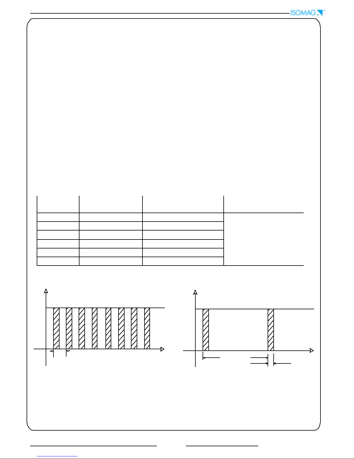
The converter can be used in two different modes:
q with continuous sampling
q with sampling to preset unit of time.
qCONTINUOUS SAMPLING (pic.1) (ENERGY SAVING OFF)
In this mode the converter make the measure in accordance with the classical diagram of the
flow meter; the consumption of the system, with any diameter of the sensor is 0,05 W ; the
life of battery is about 1 month (6 with 6 battery)
The accuracy of the system is definite in those conditions.
qSAMPLING TO PRESET UNIT TIME ( pic. 2 ) ( ENERGY SAVING ON )
This mode works sampling the range to intervals of preset time (see MEASURE menu, func.
3.5); it allows a great saving of energy
In this conditions the consumptions are:
Sampling
time (s)
Battery life - n° 1
battery (years)
Battery life – “ N “
batteries (years)
1 0,7 0,7 * N
2 1.3 1.3 * N
5 2.1 2.1 * N
10 2.7 2.7 * N
15 3.0 3.0 * N
>= 30
5
5.0 * N
Whatever the results ,
the maximum time is
limited to 10 years
FLOW RATE
SAMPLE
FREQUENCY
SAMPLE
TIME
t
t
FLOW RATE
SAMPLE
FREQUENCY
PIC 1 PIC 2
ATTENTION:
the consumptions on the table are wit
hout optional IF2 cable connected to the
converter. This device accelerate the consumption of the batteries even if the instrument is in standby
mode
. Recommends to disconnect the IF2 cable from the converter after every his uses or
switch off the converter by the dip-switches (see page 9 )
MEASURE/ CONSUMPTIONS
7
252_EN_IS_1_3_00.doc
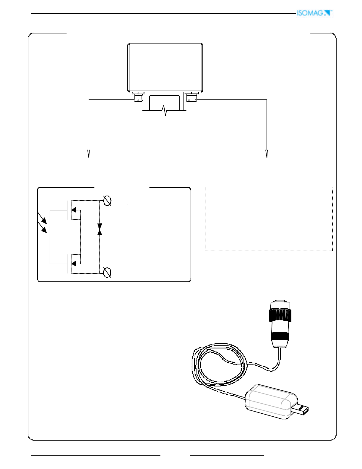
ELECTRICAL CONNECTIONS
4 poles : OUT ON/OFF
OUT 1 = Yellow ( terminal C )
OUT 2 = Pink ( terminal D )
50 V
Out common : Cyan ( terminal B )
Technical characteristics
q Opto-insulated output ( Opto- MOS )
q Maximum switching voltage: 40 Vdc
q Maximum switching current: 100mA
q Maximum Ron = 70 Ohm
q Maximum switching frequency
( loadRL=240Ω, VOUT=24Vdc): 32 Hz
q Insulation from other secondary
circuits: 500 Vdc
6 poles
q
A ( ORANGE ) : external power supply
8-35 VDC
q B ( GREEN ) : GROUND
q C ( BROWN ) : RS232 – TX
q D ( VIOLET ) : RS232 – RX
q E ( BLU ) : to IF22 USB interface
q F : not connected
IF22
8
252_EN_IS_1_3_00.doc
Before to close the converter verify the following:
q Sealing surfaces mast be clean
q Tighten the screw in cross mode up to about 12/13 Nm
q Repeat the tightening operations after 2/3 minutes
1
23
4
INSTRUMENT START UP AND MAINTENANCE
Clean surfaces
Before to switch on the instrument verify the following:
q Power supply voltage must correspond to that specified in the name plate
q Electric connections must be done as described at page 8-10
q Ground connections must be done
Verify periodically:
q Th
e integrity of the power supply cables, wiring and other electrical parts
connected
q The integrity of the instrument’s housing (this must not have bruises or other
damages that may compromises the hermetical sealing)
q The tightening of the sealing elements (cable glands, covers, etc.)
q
The integrity of the front panel (display and keyboard), damages may
compromise the sealing
q The mechanical fixing of the instrument on the pipe or on the wall stand
Tighten in cross mode
9
252_EN_IS_1_3_00.doc
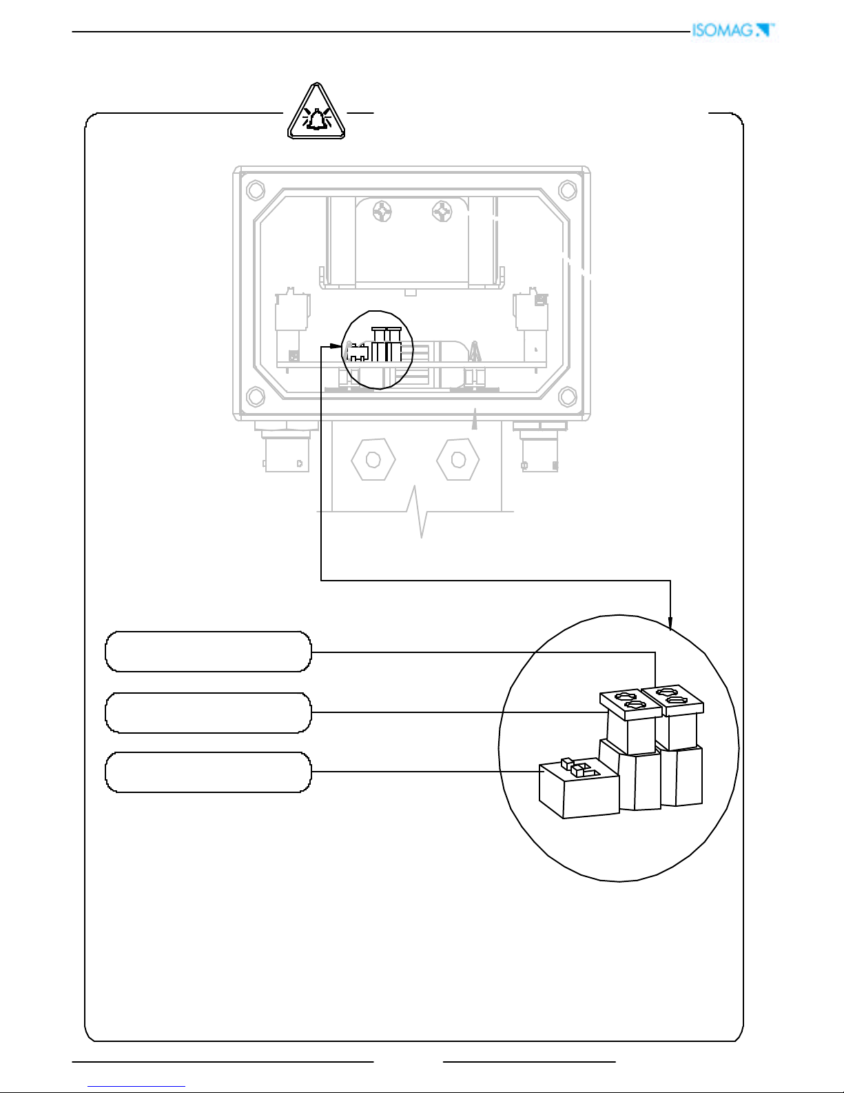
batteries pack
Batteries Power Supply
q Batteries quantity : N° 1 standard ( + N° 1 optional )
SWITCH-ON DEVICE
Switch battery 1
ON/OFF SWITCH 1-2
INSTRUMENT START UP
Switch battery 2
 Loading...