

ISOMAG ISOIL MV110 Operating And Maintenance Manual

OPERATING AND MAINTENANCE
MANUAL
MV110
110_EN_IT_IS_R3_1.00.0

Release number: 110_EN_IT_IS_R3_1.00.0
The characters of le name in bold type indicate the software version which the manual refers to; it is visualized at
the instrument start up, or by specic function on DIAGNOSTIC menu.
The reproduction of this manual and any supplied software is strictly forbidden.

110_EN_IT_IS_R3_1.00.0

INDICE
SAFETY INFORMATION __________________________________________________ 3
INTRODUCTION ________________________________________________________ 3
SAFETY CONVENTION ___________________________________________________ 4
DATA PLATE ___________________________________________________________ 5
AMBIENT TEMPERATURE _________________________________________________ 5
TECHNICAL CHARACTERISTICS ___________________________________________ 5
DIMENSIONS __________________________________________________________ 6
SEPARATE VERSION_____________________________________________________ 7
HORIZONTAL VERSION __________________________________________________ 8
VERTICAL VERSION _____________________________________________________ 8
MV110 CONSTRUCTION _________________________________________________ 10
INTERNAL LAYOUT ____________________________________________________ 11
ELECTRICAL CONNECTION AND GROUNDING INSTRUCTIONS ___________________ 12
DIGITAL INPUT ON/OFF OPERATION ______________________________________ 14
RS485 MODBUS MODULE (OPTIONAL) _____________________________________ 15
OUTPUTS WIRING _____________________________________________________ 15
DIGITAL OUTPUTS _____________________________________________________ 15
ANALOG OUTPUTS ____________________________________________________ 15
CONNECTORS MIL _____________________________________________________ 16
MEANING OF FLAGS ____________________________________________________ 19
The manufacturer guarantees only English text available on our web site www.isoil.com
MEANING OF LED COLORS _______________________________________________ 19
ACCESS VIA KEYPAD ___________________________________________________ 20
ACCESS VIA MCP INTERFACE (VIRTUAL DISPLAY) ____________________________ 20
ACCESS TO THE CONFIGURATION MENU ____________________________________ 20
FLOW RATE VISUALIZATION _____________________________________________ 21
FLOW RATE ALERT _____________________________________________________ 21
QUICK START MENU ___________________________________________________ 21
ACCESS CODE SET : MENU 13 SYSTEM ______________________________________ 22
RESTRICTED ACCESS SET : MENU 13 SYSTEM _______________________________ 22
1 di 79
110_EN_IT_IS_R3_1.00.0

CONVERTER ACCESS CODE ______________________________________________ 22
FUNCTIONS MENU _____________________________________________________ 25
FUNCTIONS DESCRIPTION ______________________________________________ 29
MENU 1 - SENSOR _____________________________________________________ 30
MENU 2 - UNITS _______________________________________________________ 33
MENU 3 - SCALE _______________________________________________________ 35
MENU 4 - MEASURE ____________________________________________________ 37
MENU 5 - ALARMS _____________________________________________________ 39
MENU 6 - INPUTS ______________________________________________________ 40
MENU 7 - OUTPUTS ____________________________________________________ 41
MENU 8 - COMMUNICATION _____________________________________________ 43
MV110 MODBUS PROTOCOL _____________________________________________ 43
MENU 9 - DISPLAY _____________________________________________________ 46
MENU 10 - DATA LOGGER _______________________________________________ 47
MENU 11 - FUNCTION __________________________________________________ 54
MENU 12 - DIAGNOSTIC ________________________________________________ 55
MENU 13 - SYSTEM ____________________________________________________ 58
MENU 14 - FILE (ONLY MCP) _____________________________________________ 64
MENU 15 - PROCESS DATA (ONLY MCP) ____________________________________ 66
METER DATA _________________________________________________________ 68
B.I.V. (BUILT-IN VERIFICATOR) __________________________________________ 69
The manufacturer guarantees only English text available on our web site www.isoil.com
SOFTWARE ISOBIV ____________________________________________________ 72
ERROR CODE TEST SYSTEM OF SENSOR ____________________________________ 73
ALARM MESSAGES (CAUSES AND ACTIONS TO BE TAKEN) ______________________ 74
2 di 79
110_EN_IT_IS_R3_1.00.0
INTRODUCTION
These operating instructions and description of device functions are provided as part of the scope
of supply.
They could be modied without prior notice. The improper use, possible tampering of the instrument
or parts of it and substitutions of any components not original, renders the warranty automatically void.
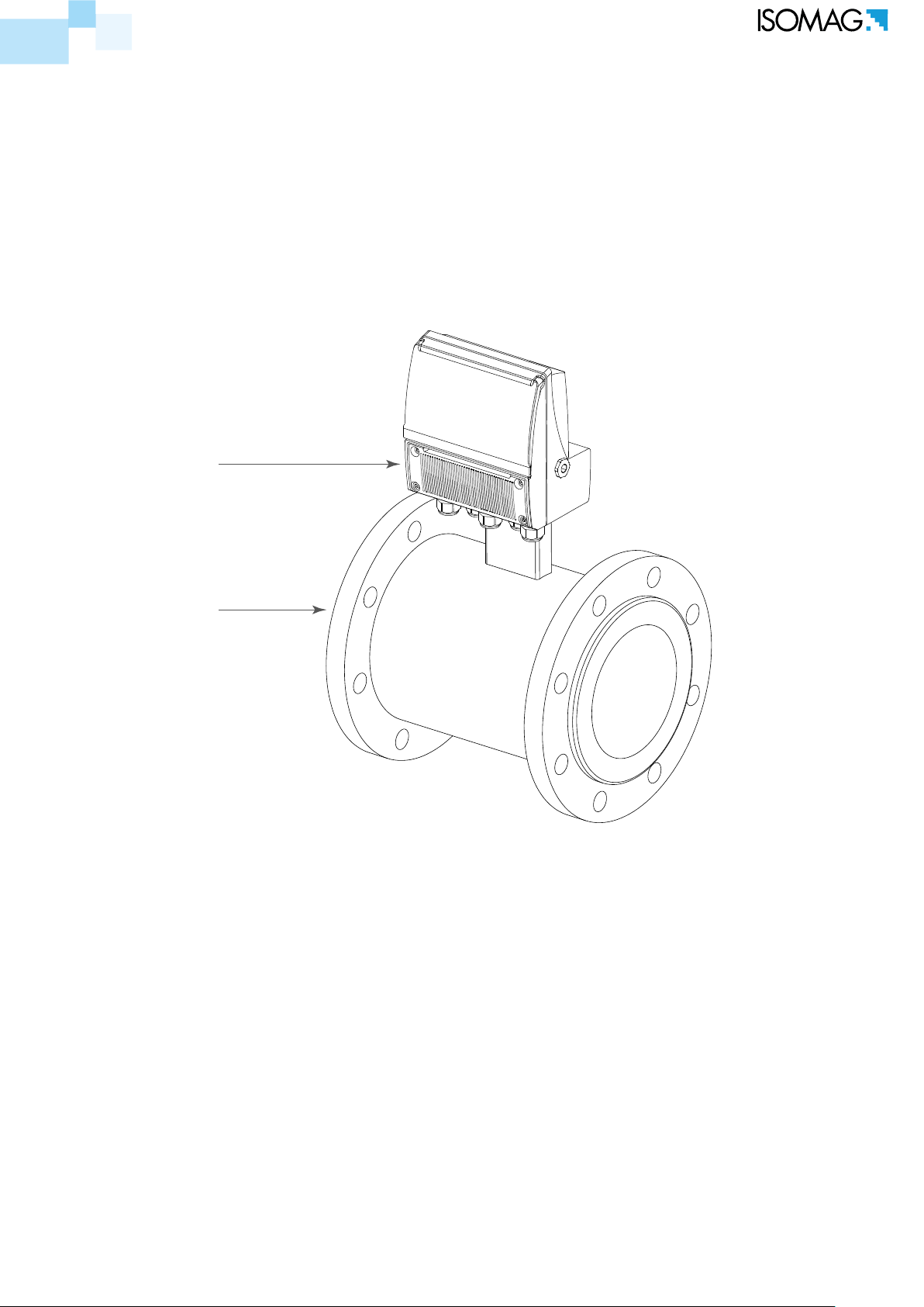
The ow meter realizes a measure with liquids of conductivity greater than 5µS/cm in closed
conduits, and is composed of a converter (described in this manual) and a sensor (refer to the
specic manual).
The converter could be coupled directly on the sensor (compact version) or coupled to the sensor
by cable supplied with it (remote version).
CONVERTER
SENSOR
The manufacturer guarantees only English text available on our web site www.isoil.com
SAFETY INFORMATION
Any use other than described in this manual aects the protection provided by the manufacturer
and compromises the safety of people and the entire measuring system and is, therefore, not
permitted. The manufacturer is not liable for damaged caused by improper or non-designated use.
Transport the measuring device to the measuring point in the original packaging. Do not remove
covers or caps until immediately before installation. In case of cartons packaging it is possible to
place one above the other but no more than three cartons. In case of wooden packaging do not
place one above the other.
Disposal of this product or parts of it must be carried out according to the local public or private
waste collection service regulations.
The converter must only be installed, connected and maintained by qualied and authorized
specialists (e.g. electrical technicians) in full compliance with the instructions in this Operating
Instruction, the applicable norms, legal regulations and certicates (depending on the application).
3 di 79
110_EN_IT_IS_R3_1.00.0

The specialists must have read and understood these Operating Instructions and must follow the
instructions it contains. The Operating Instructions provide detailed information about the converter. If
you are unclear on anything in these Operating Instructions, you must call the ISOIL service department.
The converter should only be installed after have veried technical data provided in these operating
instructions and on the data plate.
Specialists must take care during installation and use personal protective equipment as provided
by any related security plan or risk assessment.
Never mount or wire the converter while it is connected to the power supply and avoid any liquid contact
with the instrument’s internal components. To connect remove the terminals from the terminal block.
Before connecting the power supply check the functionality of the safety equipment.
Repairs may only be performed if a genuine spare parts kit is available and this repair work is
expressly permitted.
For the cleaning of the device use only a damp cloth, and for the maintenance/repairs contact the
service center (for details see the last page).
Before starting up the equipment please verify the following:
Power supply voltage must correspond to that specied on the data plate
Electric connections must be completed as described
Ground (earth) connections must be completed as specied
Verify periodically (every 3-4 months):
The power supply cables integrity, wiring and other connected electrical parts
The converter housing integrity
The suitable tightness of the sealing elements
The front panel integrity (display and keyboard)
The manufacturer guarantees only English text available on our web site www.isoil.com
The mechanical xing of the converter to the pipe or wall stand
SAFETY CONVENTION
DANGER ELECTRIC SHOCK
4 di 79
WARNING
PRECAUTIONS
110_EN_IT_IS_R3_1.00.0
ATTENTION
ElEctrical charactEristic
Converter classication: class I, IP67/68 for aluminum and PA6 housing, installation category
(overvoltage) II, rated pollution degree 2.
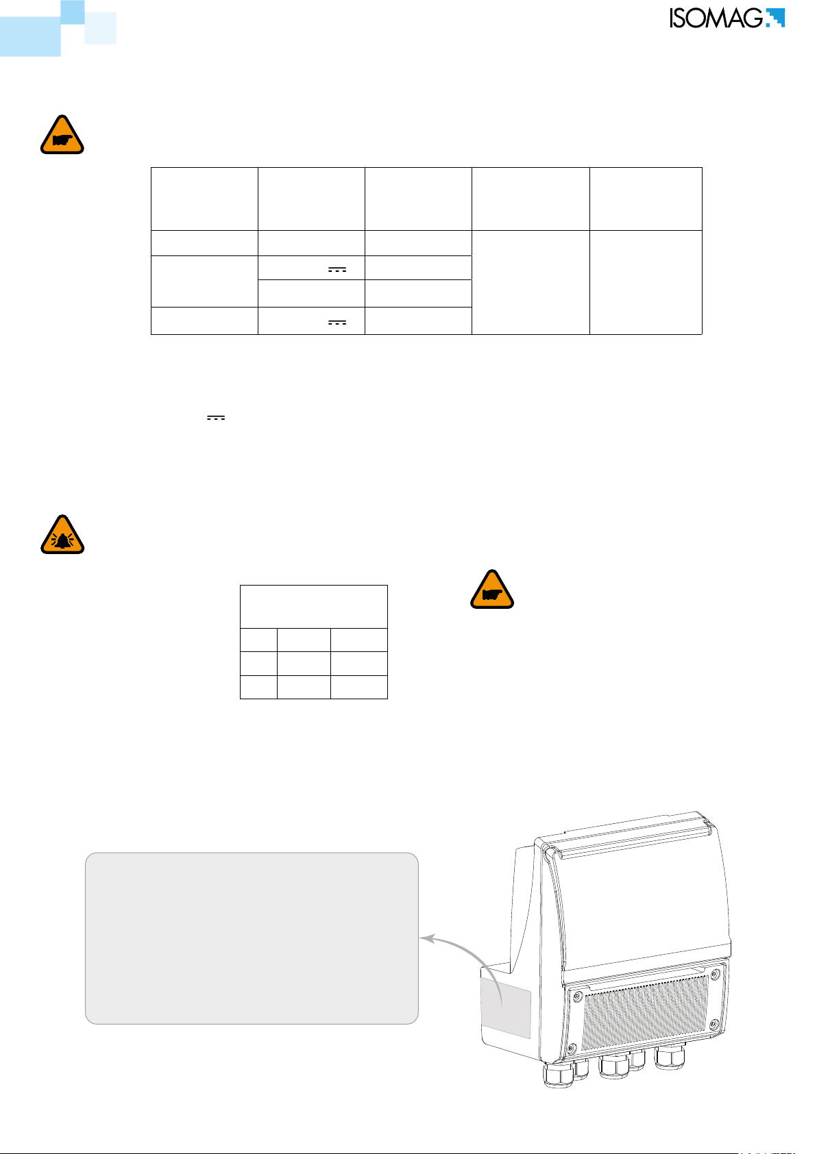
TECHNICAL CHARACTERISTICS
Power
supply
versions
Power
supply
voltage
Power
supply
frequency
Min
Power
Max power
HV 100-240V~ 45-66HZ
LV
24-36V
24-36V~ 45-66HZ
LLV 12-48V
//
//
1,5 W
(Sensor only)
5 W
(all Loads)
Voltage variations must not exceed ±10% of the nominal one.
Input/output insulated up to 500V.
The output 4-20mA (optional) is electrically connected to the ON/OFF outputs and the output
power supply (24V
).
Version LV/LLV : inrusch current < 20A
Version HV : inrusch current < 25A
EnvironmEntal UsE conditions
The converter can be installed internally or externally
Altitude: from –200m to 4000m (from -656 to 6560 feet)
Humidity range: 0-100%
AMBIENT
ATTENTION
TEMPERATURE
Min* Max
°C -10 60
°F 14 140
The manufacturer guarantees only English text available on our web site www.isoil.com
If the converter is supplied in compact version (converter over the sensor), consider the ambient
The battery will not be charged outside the
below limits :
T board MV110 < 0 °C
T board MV110 > 50 °C
temperatures more restrictive, otherwise refer to the relevant manuals.
* For discontinuous use, a thermostat heat source installation may be necessary.
data PlatE
The instrument label contain the following information:
MODEL: Convert Model
S/N: Serial Number of the converter
SUPPLY: Main power supply
Hz: Supply frequency (AC)
POWER: Maximum power consumption
IP: Protection grade
T: Operation temperature
COUPLING: Serial number of sensor coupled
ITEM: Free for user
5 di 79
110_EN_IT_IS_R3_1.00.0

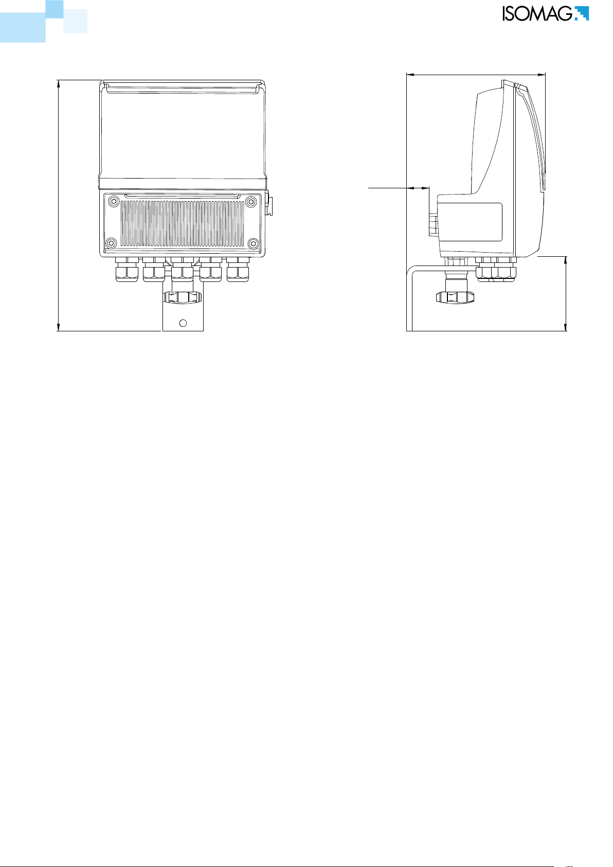
200.0
DIMENSIONS
167.0
The manufacturer guarantees only English text available on our web site www.isoil.com
114.0 164.0
290.0
176.0
6 di 79
114.0
195.0
110_EN_IT_IS_R3_1.00.0
sEParatE vErsion
252.0
136.5
22.5
76
The manufacturer guarantees only English text available on our web site www.isoil.com
7 di 79
110_EN_IT_IS_R3_1.00.0
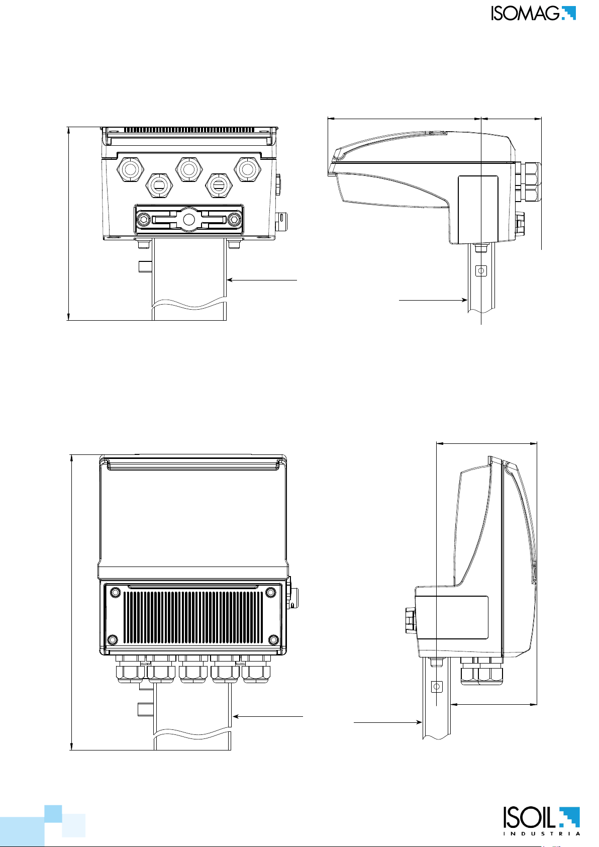
horizontal vErsion
200.0
vErtical vErsion
JUCTION BOX
144.0
JUCTION BOX
56.0
The manufacturer guarantees only English text available on our web site www.isoil.com
270.0
JUCTION BOX
87.0
75.0
JUCTION BOX
8 di 79
110_EN_IT_IS_R3_1.00.0
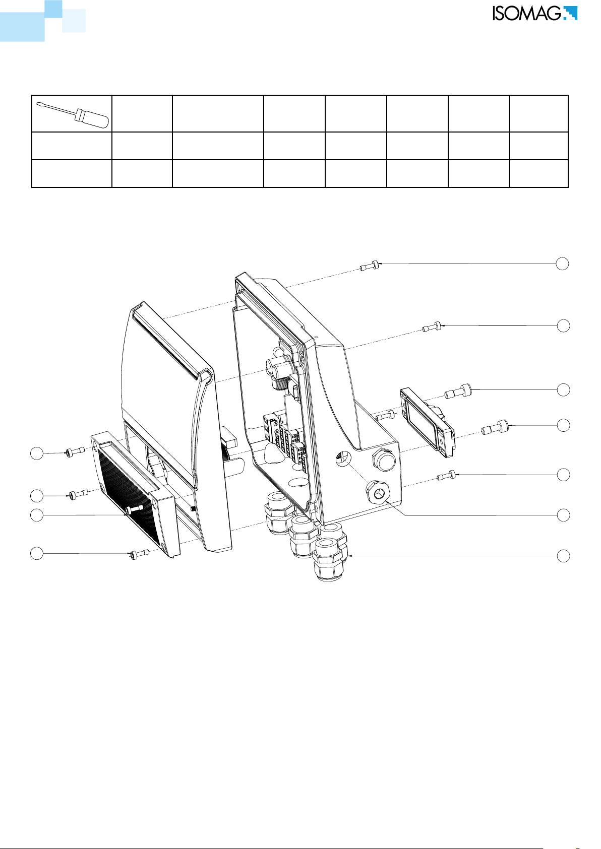
TORQUES
To guarantee the housing’s IP degree the following torques are required:
ALUMINIUM
HOUSING
PLASTIC
HOUSING
Housing
screw (1)
Cover terminal
block screw (2)
Fixing
Display
Frame
PCB
Screw
Version
Cap (3)
Cable
Glands (4)
USB-B (5)
6 Nm 5.5 Nm 3 Nm 0.8 Nm 8 Nm 4 Nm 4 Nm
2 Nm 2 Nm 2.5 Nm 0.8 Nm 7 Nm 4 Nm 4 Nm
Cap
1
1
3
The manufacturer guarantees only English text available on our web site www.isoil.com
3
2
1
2
2
2
5
4
9 di 79
110_EN_IT_IS_R3_1.00.0

MV110 CONSTRUCTION
TERMINAL BLOCK COVER
1
2
3
4
MAIN HOUSING COVER
The manufacturer guarantees only English text available on our web site www.isoil.com
10
11
12
13
14
15
16
5
DESCRIPTION
POS.
PA6 VERSION ALUMINIUM VERSION
6
7
8
9
PCB MV110
MAIN HOUSING
24
1 SCREW M4x12 SCREW M5x12
2 GROWER Ø4 GROWER Ø5
3 TERMINAL BLOCK COVER TERMINAL BLOCK COVER
4 O-RING-4400
5 PROTECTION COVER
6 HOUSING COVER HOUSING COVER
7 ORING-4700
8 ORING-117x3
9 DISPLAY
10 FIXING DISPLAY FRAME (MATERIAL PA06)
11 SELF-TAPPING SCREW 4x10 TRILOBO SCREW 4x10
12 SELF-TAPPING SCREW 4x10 TRILOBO SCREW 4x10
13 PCB MV110
14 PG9 CAP
15 LITHIUM BATTERY
16 ANTICONDESE CAP
17 PA6 MAIN HOUSING ALUMINIUM MAIN HOUSING
18 GROWER Ø4 GROWER Ø5
19 SCREW M4x12 SCREW M5x12
20 O-RING-155
21 VERSION CAP (MATERIAL PA06)
22 SCREW M6x16
23 GROWER Ø6
24 PG11 CABLE GLAND
17
18
19
20
21
22
23
10 di 79
110_EN_IT_IS_R3_1.00.0
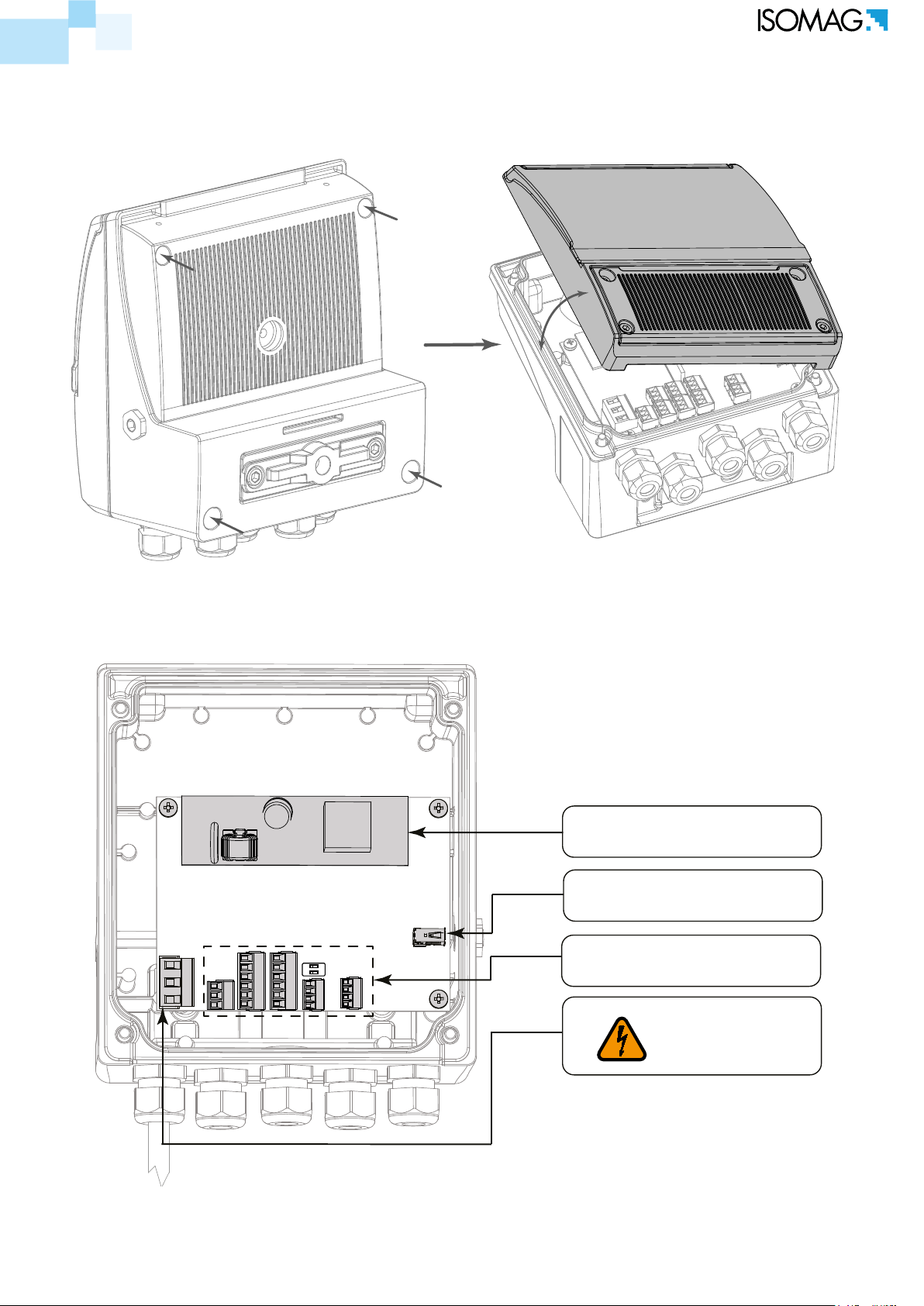
INTERNAL LAYOUT
Internal Converter vIews
Remove the main housing cover by removing the 4 screws as shown here below.
The manufacturer guarantees only English text available on our web site www.isoil.com
POWER SUPPLY CABLE
POWER SUPPLY BOARD
MINI USB-B
1 2
ON
TERMINAL BLOCKS
MAIN POWER
SUPPLY
11 di 79
110_EN_IT_IS_R3_1.00.0
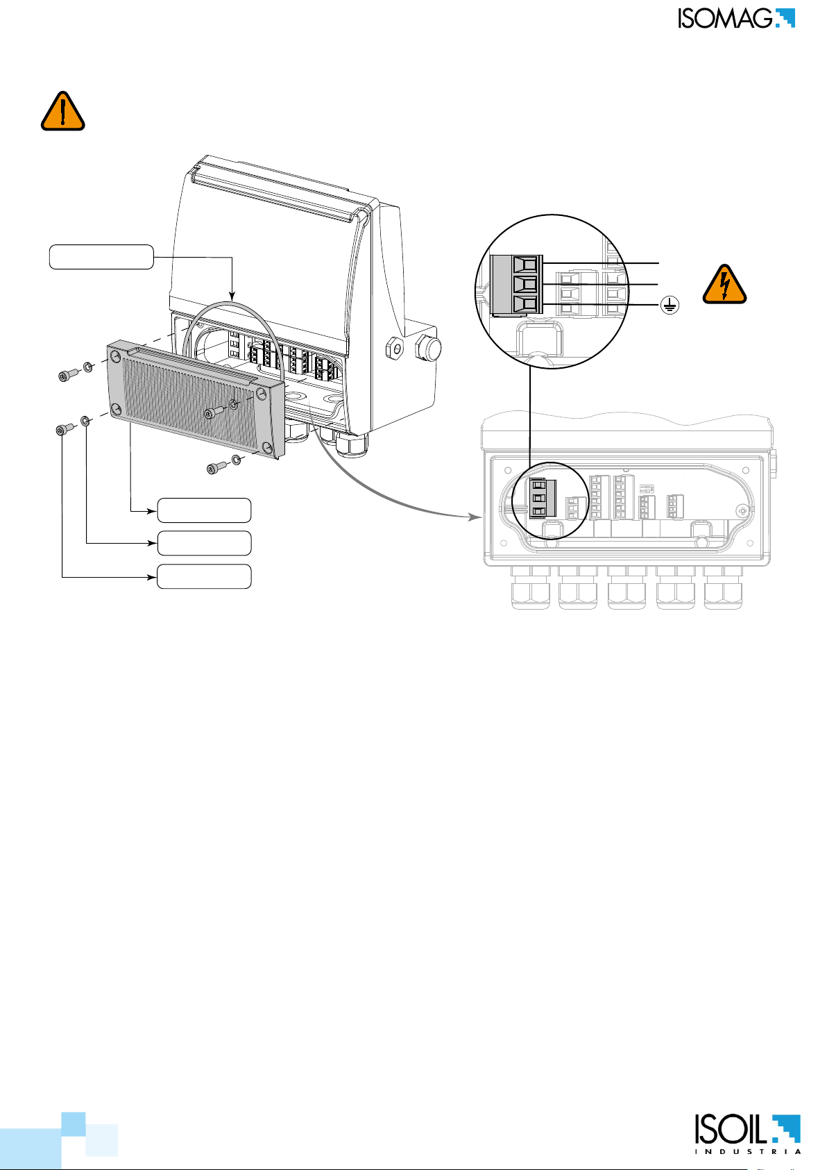
ELECTRICAL CONNECTION AND GROUNDING INSTRUCTIONS
Always ensure that the converter and the sensor are grounded (earthed) correctly. The grounding
of the sensor and converter must ensure that the instrument and liquid are equipotential.
ORING 4700
L(+)
N(-)
COVER
GROWER
SCREW
Before connecting the power supply, verify that the mains voltage is within the limits indicated on
data plate.
For the connections use only approved conductors, with re-proof properties, whose section varies
from 0.25mm2 to 1.50mm2, based on distance/power; additionally x the power supply wires with
The manufacturer guarantees only English text available on our web site www.isoil.com
a additional fastening system located close to the terminal.
The power supply line must be equipped with an external protection for overload current (fuse or
automatic line breaker).
Provide in close proximity the converter a circuit breaker easily accessible for the operator and clearly
identied; whose symbols must conform to the electrical safety and local electrical requirements.
Ensure that the component complies with the requirements of the standard for electrical safety
distance.
Check chemical compatibility of materials used in the connection security systems in order to
minimize electrochemical corrosion. In the aluminum housing it should avoid direct contact between
the ground connection cable and the aluminum housing. It is therefore recommended to connect
the safety ground cable, by placing it between the washer and the metal bracket on the related
terminal or use an eyelet terminal crimped on the ground protection cable.
The sensor, hardwired inputs and outputs are connected to the converter through terminal blocks
located inside the converter.
To locate the terminal block loosen the 4 screws on the terminal block cover. When the front cover
is lifted, the terminal block is visible. The terminal block is the hardwire connection of the converter
to external equipment, including the sensor.
The following pages give informations on the terminal block numbering, and the respective connecting
of the sensor cables, and inputs/outputs.
12 di 79
110_EN_IT_IS_R3_1.00.0
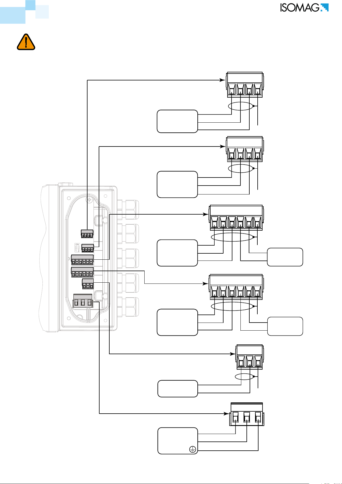
ELECTRICAL CONNECTION CONVERTER- SENSOR
Sudden movements of the electrodes cable could introduce noise.
*SH = SHIELD OF CABLE internally connected to ground.
ELECTRODES
RS485
E1
E2
0V
321 4
C
SH*
272829 26
B
A
SH*
The manufacturer guarantees only English text available on our web site www.isoil.com
4-20 OUTPUTS
OUT2 (+) 4-20
OUT1 (+) 4-20
OUT1-2 (-) 4-20
DIGITAL OUTPUTS
OUT2 C
OUT1 C
OUT 1-2 E
COILS
C1
C2
232425 22
171819 16
13 12 11
21
15
20
SH*
14
SH*
SH*
+24V
0V
DIGITAL
INPUTS
IN1 +
IN1 -
13 di 79
POWER SUPPLY
L (+)
N( - )
110_EN_IT_IS_R3_1.00.0
0-1.5V
3-40V
Block Totalizers
Totalizers Active
3-40V
0-1.5V
T
Reset
Tmin=100ms
Block
0-1.5V
3-40V
Scale 2
Scale 1
<18v
18-30V
Measure blocked
Measure
10KΩ
3-40Vdc (ON)
0/1.5Vdc (OFF)
15(+)
16(+)
10KΩ
16
22
10KΩ
15
21
+24
-0
RESET TOTALIZERS
BLOCK TOTALIZERS
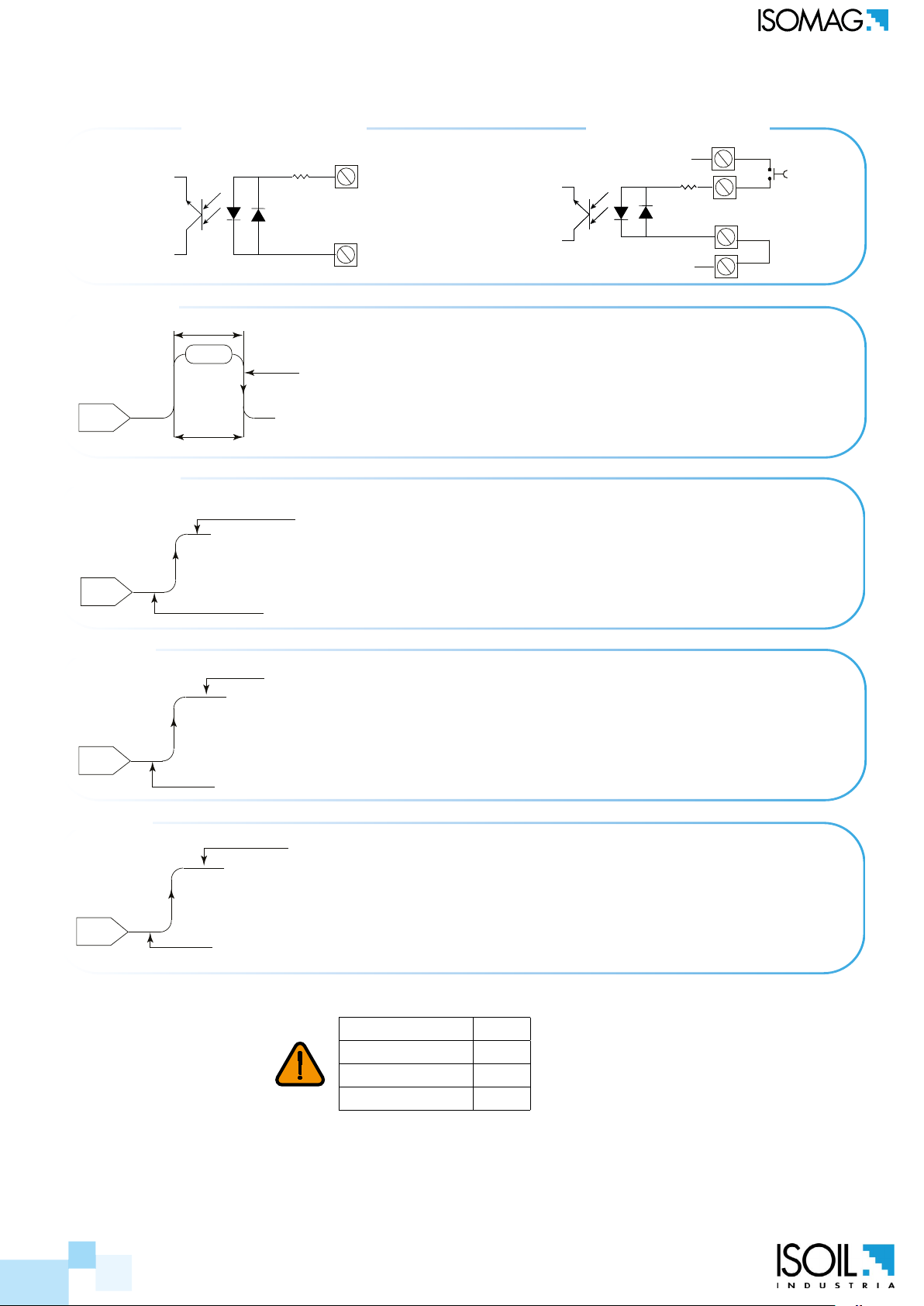
DIGITAL INPUT ON/OFF OPERATION
EXTERNAL POWER SUPPLY INTERNAL POWER SUPPLY
Necessary conditions for enabling the function
POS. 6.1 see page 26 (T+; total direct positive set on)
POS. 6.2 see page 26 (P+; partial direct positive set on)
POS. 6.3 see page 26 (T-; total direct negative set on)
POS. 6.4 see page 26 (P-; total direct negative set on)
Necessary conditions for enabling the function
POS. 6.5 see page 26 (Totalizer counting lock command set on)
RANGE CHANGE
The manufacturer guarantees only English text available on our web site www.isoil.com
MEASURE LOCK
Necessary conditions for enabling the function
POS. 6.8 see page 26
(Range change set on)
Necessary conditions for enabling the function
POS. 6.6 see page 26 (Totalizer counting lock command set on)
SAMPLE RATE Tmin
10HZ 220ms
20HZ 110ms
50HZ 45ms
MUST BE
T > Tmin
14 di 79
110_EN_IT_IS_R3_1.00.0
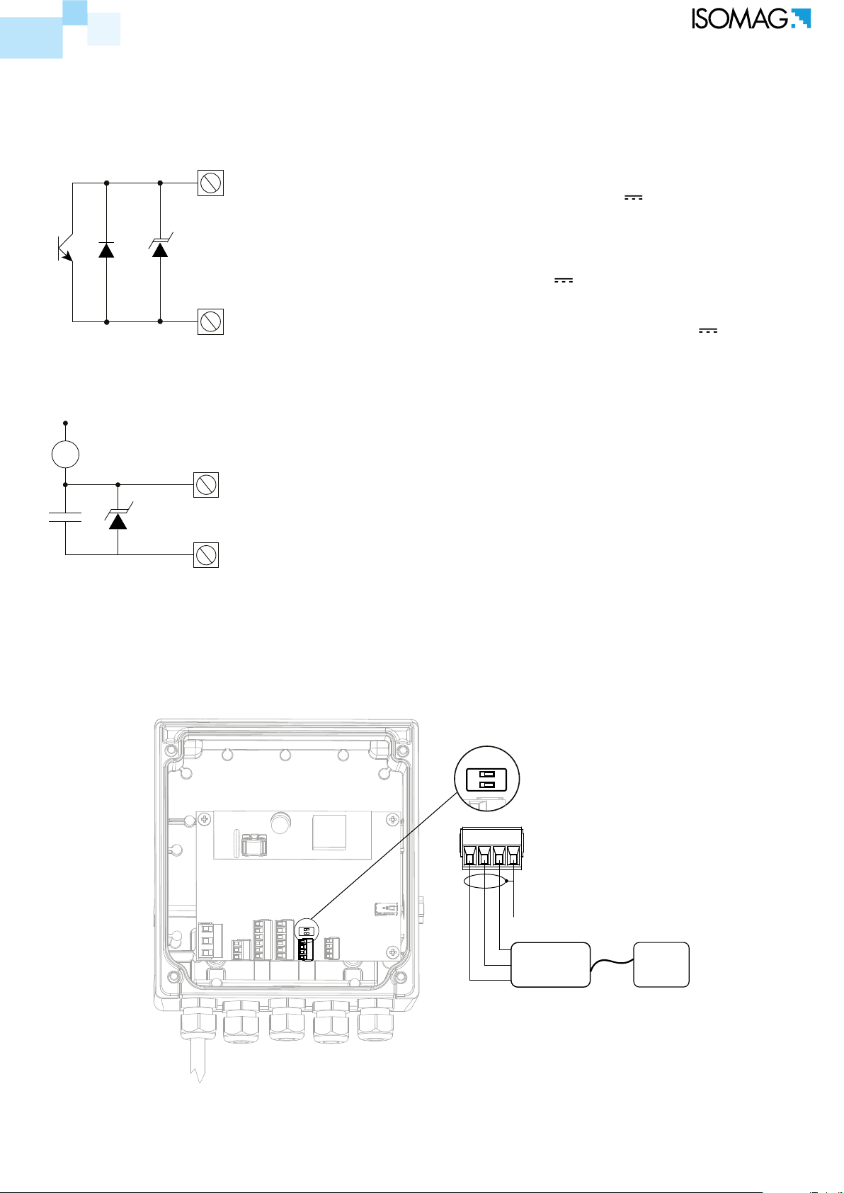
OUTPUTS WIRING
DIGITAL OUTPUTS
18 OUT 1(+)
19 OUT 2(+)
17 (COM. OUT 1-2)
ANALOG OUTPUTS
Opto-insulated output with oating collector and emitter
terminals freely connectable
Maximum switching voltage: 40V
Maximum switching current: 150mA
Maximum saturation voltage between collector and emitter
@150mA: 1.2V
Maximum switching frequency (load on the collector or emitter,
RL=470, VOUT=24V
): 1250Hz
Maximum reverse current bearable on the input during and
accidental polarity reversion (VEC): 100mA
Insulation from other secondary circuits: 500V
mA
24 OUT 1(+)
25 OUT 2(+)
Opto-insulated output
Maximum load: 1000Ω
Maximum voltage without load: 27V
Refresh frequency is the same of the sample frequency of the
connected sensor
23 (COM. 4-20 OUT 1-2)
Protected against persistent over voltages to maximum 30V
RS485 MODBUS MODULE (OPTIONAL)
Positioning to ‘ON’ the termination switches 1 and 2, a 120Ω résistance is activated in the RS458 circuit (see
terminal block).
The manufacturer guarantees only English text available on our web site www.isoil.com
1 2
ON
272829 26
TERMINATION
SWITCH
TERMINAL BLOCK
15 di 79
1 2
ON
110_EN_IT_IS_R3_1.00.0
SH
0V
A
RS485
B
PC
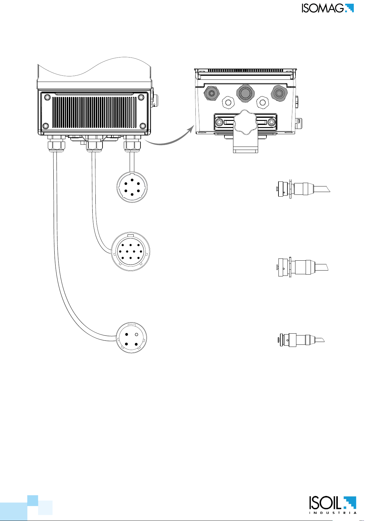
CONNECTORS MIL
THE following are the links of the MIL connectors IP68
The manufacturer guarantees only English text available on our web site www.isoil.com
SENSOR SIGNALS
A
B
A contact from terminal 1 of the converter (electrode 1)
F
Contact F from terminal 2 of the converter (electrode 2)
Connector
6 poles
Contact And from terminal 3 of the converter (COM. Elec.)
C
D
Contact B from terminal 13 of the converter (COIL 1)
E
Contact C from terminal 12 of the converter (COIL 2)
Contact D from terminal 4 and 11 of converter
(SHIELD electrodes - COILS)
INPUT/OUTPUT
1. Contact B from terminal 24 of the converter (Out1 4-20 +)
2. Contact A from terminal 25 of the converter (Out2 4-20 +)
A HB
J
K
C
D
E
3. Contact H from terminal 23 of the converter (Out1-2 4-20 -)
4. Contact C from terminal 21 of the converter (+ 24V)
G
5. Contact J from terminal 22 of the converter (0V)
F
6. Contact K from terminal 15 of the inverter (IN1 +)
Connector
10 poles
7. Contact G from terminal 16 of the converter (IN1-)
8. Contact D from terminal 19 of the converter (C Out2)
9. Contact E from terminal 18 of the converter (Out1 C)
10. Contact F from terminal 17 of the converter (Out1-2 E)
11. Contact C from terminal 28 of the converter (RS485 A)
12. Contact J from terminal 29 of the converter (RS485 B)
NB: the connections 4 and 5 exclude the use
connections 11 and 12.
Connector
D
A
B
C from terminal L power converter (+ dc)
A from terminal N power converter (-dc)
C
B from terminal GROUND Power Converter
POWER SUPPLY
4 poles
NOTE: Military Connector 6 poles for sensor converter only provided in the separate version of the converter.
16 di 79
110_EN_IT_IS_R3_1.00.0
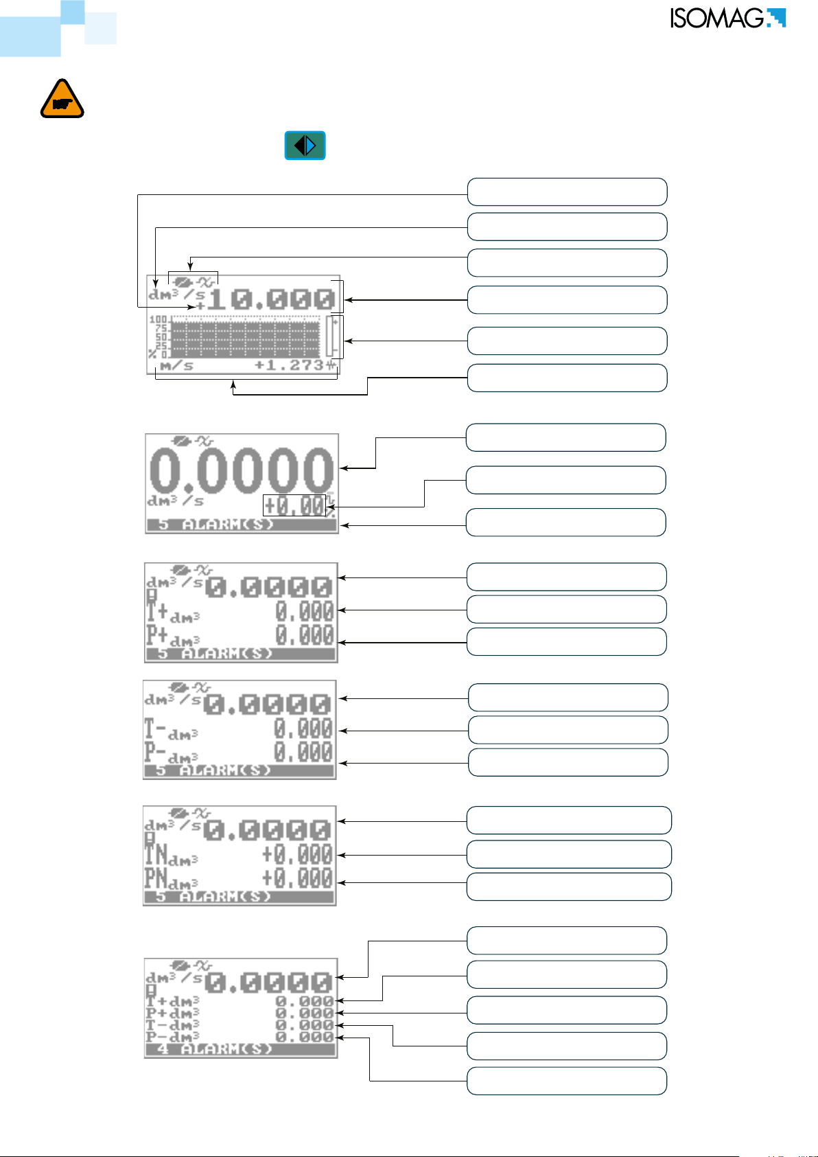
START VISUALIZATION PAGES
The direct exposure of the converter to the solar rays, could damage the liquid crystal display.
The visualization pages can be change according to instrument’s setup.
Push to change visualization
Flow rate direction +/-
Unit of measure
Flag
Flow rate value
Flow rate trend
Flow Speed
Flow rate value
The manufacturer guarantees only English text available on our web site www.isoil.com
% Full Scale
n° ALARM
Flow rate value
Direct Total Totalizer
Direct Partial Totalizer
Flow rate value
Reverse Total Totalizer
Reverse Partial Totalizer
Flow rate value
Totalizer Total Net
17 di 79
Totalizer Partial Net
Flow rate value
Direct Total Totalizer
Direct Partial Totalizer
Inverse Total Totalizer
Inverse Partial Totalizer
110_EN_IT_IS_R3_1.00.0

Push to change visualization
Totalizer Total +
Totalizer Partial +
Totalizer Total -
Totalizer Partial -
Electrodes Voltage
Electrodes Resistance
n°Alarm
Alarm List
The manufacturer guarantees only English text available on our web site www.isoil.com
Date and Time
Direct Total Totalizer
Direct Partial Totalizer
Reverse Total Totalizer
18 di 79
Reverse Partial Totalizer
110_EN_IT_IS_R3_1.00.0
!
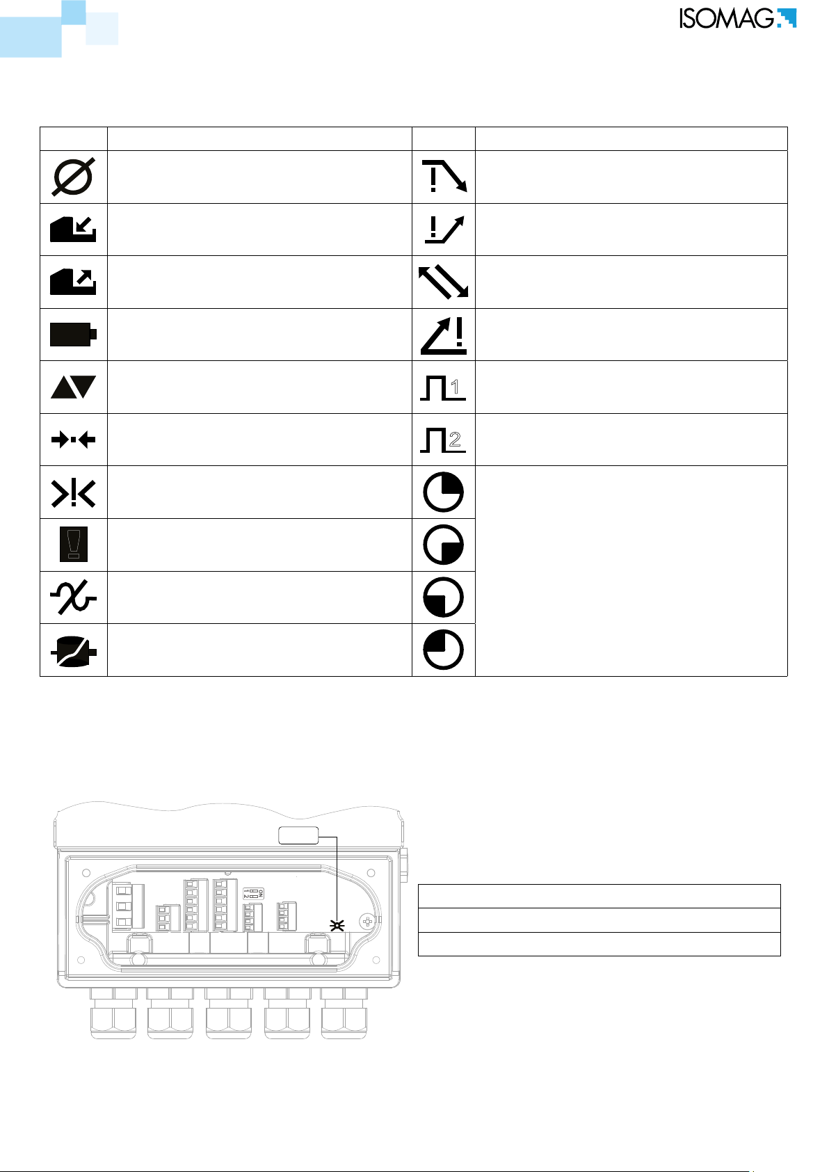
mEaninG oF FlaGs
FLAG DESCRIPTION FLAG DESCRIPTION
EMPTY PIPE MIN FLOW ALARM
FILE UPLOAD MAX FLOW ALARM
FILE DOWNLOAD VIDEO TERMINAL CONNECTED
BATTERY RECHARGE (FLASHING)
LOW BATTERY (FIXED)
FLOW RATE SIMULATION (FLASHING)
CALIBRATION (FLASHING)
GENERIC ALARM (FLASHING)
GENERAL ALARM ONLY ON PHYSICAL
DISPLAY (FLASHING)
SIGNAL ERROR
EXCITATION ERROR
FLOW RATE OVERFLOW
1
2
PULSE 1 OVERFLOW
PULSE 2 OVERFLOW
POWERED DEVICE WITH ONE
CHARGERS BATTERY (MID-DIRECTIVE)
The manufacturer guarantees only English text available on our web site www.isoil.com
mEaninG oF lEd colors
LED
LED Red: Alarm signal
LED Blue: Usb communication enable
LED Green: Functioning system correctly
19 di 79
110_EN_IT_IS_R3_1.00.0

ACCESS TO THE CONFIGURATION MENU
ENTER
ESC
Mini-B
54321
The conguration can be done in two dierent ways:
By keypad of converter
By MCP interface (Virtual display of instrument)
accEss via KEyPad
SHORT PRESSING (< 1 SECOND):
Increases the numeric gure or the
parameter selected by the cursor
Returns to the previous subject on the
menu.
LONG PRESSING (> 1 SECOND):
Decreases the numeric gure or the
parameter selected by the cursor.
Proceeds to the next subject on the menu.
SHORT PRESSING (< 1 SECOND):
Moves/positions the cursor rightward
on the input eld. Proceeds to the
following subject of the menu. Change
the display of the process data
LONG PRESSING (> 1 SECOND):
Moves/positions the cursor leftward
on the input eld. Returns to the
previous subject on the menu
SHORT PRESSING (< 1 SECOND):
Enter /leave the selected function
Enables the main menu for the
instrument conguration Cancels the
selected function under progress
LONG PRESSING (> 1 SECOND):
Leaves the current menu
Enables the totalizer reset request
(when enabled) Conrms the selected
function.
accEss via mcP intErFacE (virtUal disPlay)
The manufacturer guarantees only English text available on our web site www.isoil.com
MCP is a Windows® software that allows to set all the converter functions and personalize the menu.
The MCP program is required for the blind version of the converter. To use MCP interface consult the
relevant user manual.
MCP INTERFACE
PG9 CAP
USB CABLE
20 di 79
Type-A
110_EN_IT_IS_R3_1.00.0

FLOW RATE VISUALIZATION
This symbol appears (red color on the
virtual display) only when the overall
noise is over 2.5% of ow rate.
The MV 110 can show a 5 digits display for ow rate units; this mean the maximum ow rate value
that can be represented on the display is 99999 (no matter the positioning of the decimal point). The
minimum is 0.0025. The representable measure unit depends on sensor ow rate and diameter; the
permitted units are those, that permits the instrument full scale value not exceeding 99999.
Example for DN 300, Full scale value: 3m/s:
PERMITTED measure unit (example): l/s (216.00); m3/h (777.60); m3/s (0.2160)
NOT PERMITTED measure unit (example): l/h (777600)
FLOW RATE ALERT
This FLAG becomes active when there is a ow variation (ow rate not stable).
The manufacturer guarantees only English text available on our web site www.isoil.com
QUICK START MENU
The QUICK START MENU allows to user immediate access to some of the most commonly used functions;
through MCP software it possible customize this menu to make it suitable for the specic application.
Access to all functions
See programming
functions section
The user has immediate access to the Quick Start menu when the converter is powered up by pressing
the Enter key. If access to the quick start menu does not occur, then it could be disabled using the
function “9.11 Quick start menu visualization” page 27 .
21 di 79
110_EN_IT_IS_R3_1.00.0
CONVERTER ACCESS CODE
The access for programming the instrument is regulated by six access levels logically grouped.
Every level is protected by a dierent code.
Access Level 1-2-3-4 Freely programmable by user
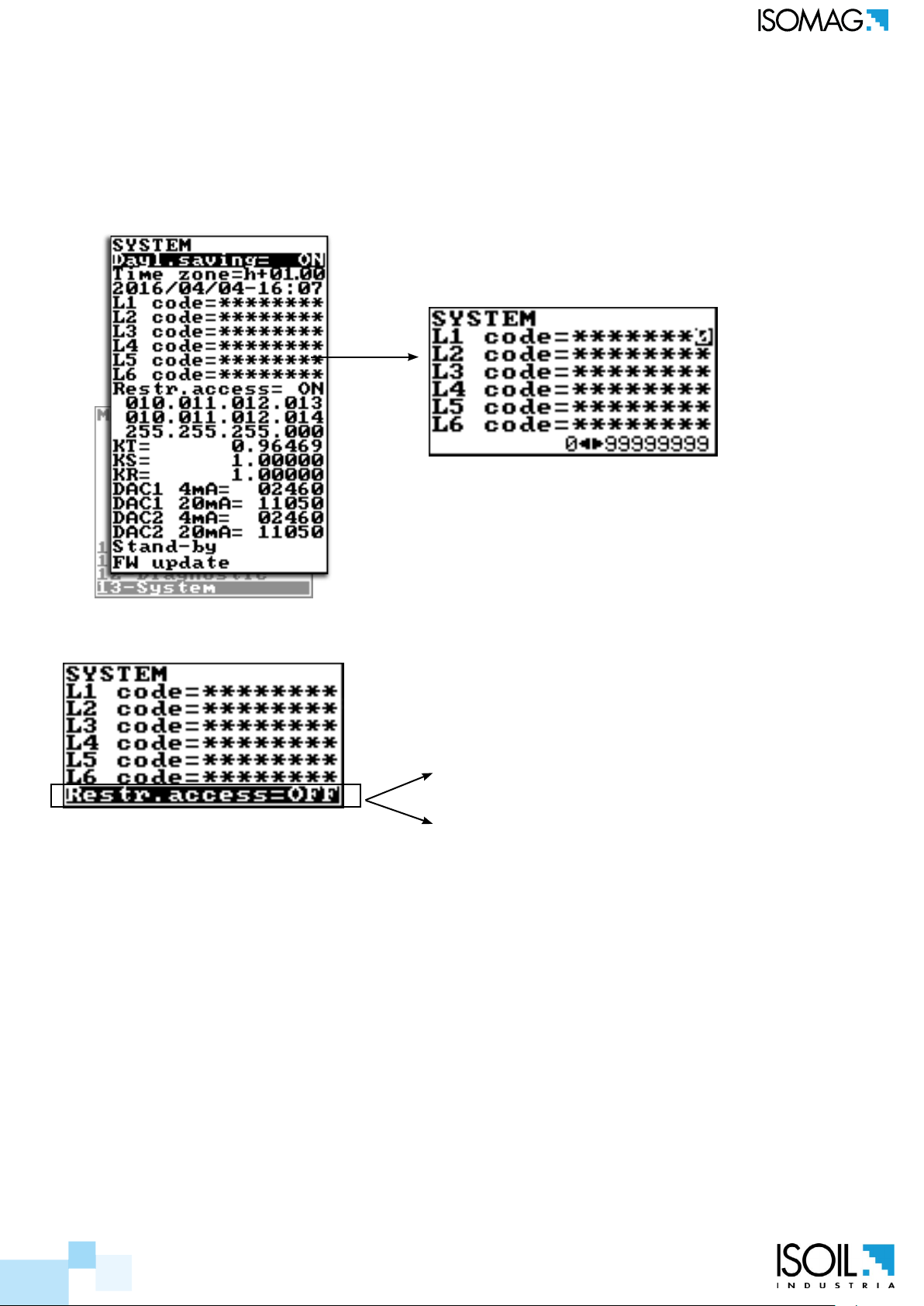
accEss codE sEt : mEnU 13 systEm
The CODE is Settable by keyboard or MCP interface.
Depending on the level of access dierent display functions will be
visible. (See section “FUNCTIONS DESCRIPTION” page 29)
These access levels interact with the “Restricted access”
rEstrictEd accEss sEt : mEnU 13 systEm
Settable Values
ON
The manufacturer guarantees only English text available on our web site www.isoil.com
OFF
Restrict = ON: Access permitted only to functions provided for a specic level;
Example: If the operator has a code of access level 3, after having set it, he can change only the
functions with level 3 access.
Restict = OFF: It enables to change functions for the selected level and ALL the functions with lower
access level.
Example: If the operator has the code of level 3, after having set it, he can change all the functions at
level 3 and those at lower levels.
* WARNING: take careful note of the customized code, since there is no way for the user to retrieve
or reset it if lost.
Factory preset access codes:
22 di 79
L1: 10000000
L2: 20000000
L3: 30000000
L4: 40000000
110_EN_IT_IS_R3_1.00.0
 Loading...