

DUAL TECH 2.0 - DTH2 SERIES
DIE CAST ALUMINUM LED EXIT SIGNS
INSTALLATION AND OPERATING
INSTRUCTIONS
IMPORTANT SAFEGUARDS
When using electrical equipment, basic safety precautions should always be followed including
the following:
READ AND FOLLOW ALL SAFETY INSTRUCTIONS
1. DO NOT use outdoors.
2. DO NOT mount near gas or electric heaters.
3. Equipment should be mounted in locations and at heights where it will not be
readily subject to tampering by unauthorized personnel.
4. The use of accessory equipment is not recommended by the manufacturer.
Use of such equipment may cause an unsafe condition.
5. DO NOT use this equipment for other than intended use.
6. Conduct periodic visibility tests in accordance with the applicable installation
code (such as NFPA 101).
7. Supply connections MUST be made inside the junction box.
8. Install using recommended junction box ONLY.
9. Servicing of this equipment should be performed by a qualified service personnel.
10. Install sign indoors only where not exposed to direct unfiltered sunlight, liquid
spray or temperatures outside of the range of 10 C to 40 C.
11. Before installing unit, disconnect power at breaker panel.
o o
CONSERVER LA FICHE D’INSTRUCTION
Z410138 Rev B
SAVE THESE INSTRUCTIONS
31 Waterloo Avenue • Berwyn • PA 19312 U•S•A
Telephone: (610) 647-8200 • Fax: (610) 296-8952
Page 1

INSTALLATION INSTRUCTIONS
The Dual Tech 2.0 Hybrid Exit Sign is designed to be mounted to a junction box (supplied by
others). It can be either back, top or side mounted. The single face unit back mounts to a
standard 4” square box. Top or side mount requires the optional canopy and also mounts to
a standard 4” square box.
1 ½
4.0
4.78 Between mounting holes
3 ⅜
3 ⅜
4.0
Figure 1: Standard Junction box dimensional outline
SECTION 1: BASIC FUNCTIONALITY AND FEATURES
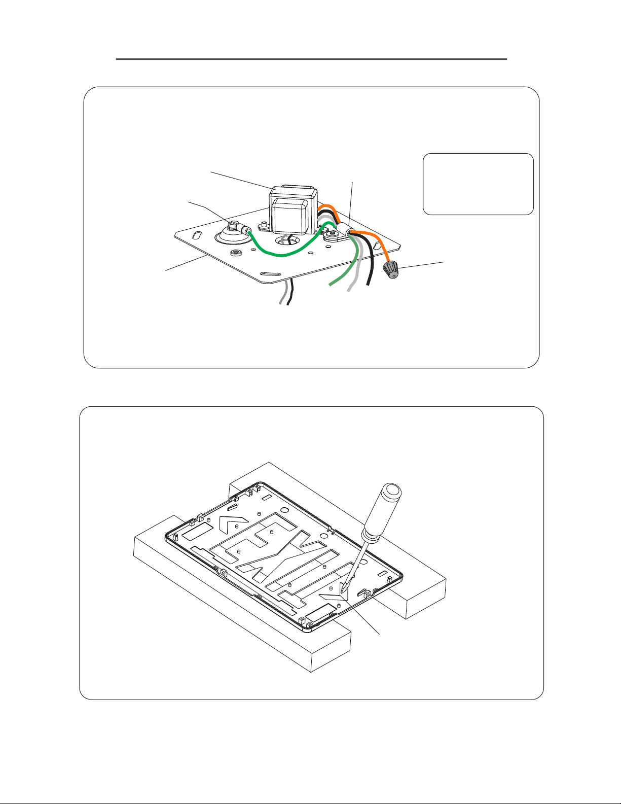
1. Open enclosure and separate panels using a flat blade screw driver (as shown below).
To open the sign insert a flat blade screwdriver
into the 4 slots on the edge and rotate
the blade gently so that the sign snaps
apart. Repeat on all notches before
pulling apart.
2. Support rear panel on spacers and punch out appropriate knockouts to fit junction box.
Z410138 Rev B
Figure 2: Opening the sign
Junction Box Knockouts
Knockout for lead
wires to sign.
Figure 3: Rear Panel Knock Outs
Page 2
Before installing unit, disconnect power at breaker panel
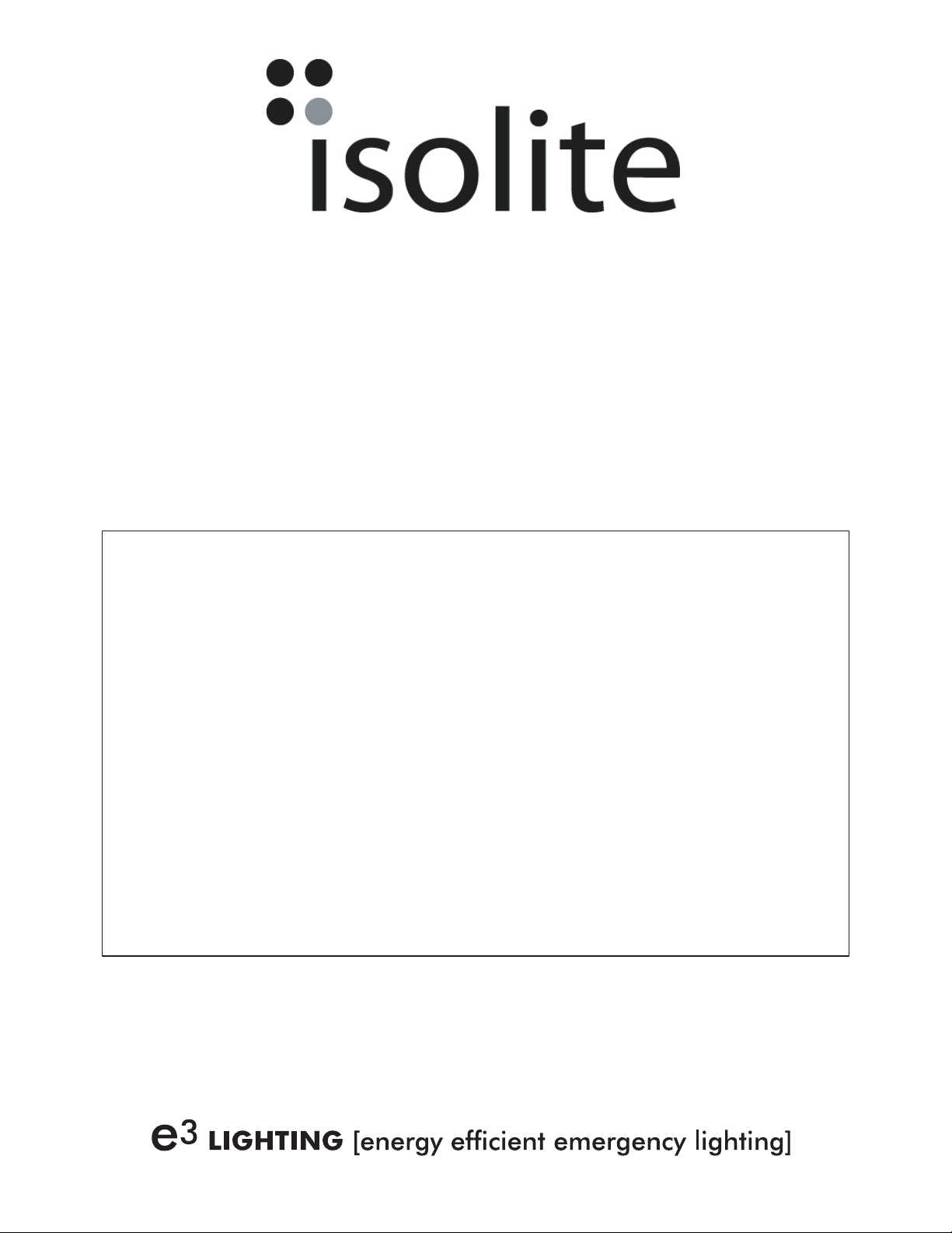
3. The spider plate assembly will be provided with the transformer mounted and the lead
wires strain relieved by the cable clamp (as shown below). Connect lead wires to feed
wires in junction box as per local code.
Black lead for 120V OR
Orange lead for 277V
White lead for neutral
Green Lead for Ground
(CAP UNUSED LEAD)
Cap unused
primary wire
Protected Earth
Ground Screw
spider plate
Transformer
routed through center
hole on spider plate
Secondary wires
to Exit Sign
Cable clamp
(strain relief)
Green
Ground
White
Neut
Black
120V
Orange
277V
Figure 4: Lead wire connections to transformer
4. Determine which directional indicators are to be removed. Remove light guide assembly
and set aside. Support front cover as shown below and knock out desired directional indicator(s).
Z410138 Rev B
Knock out desired directional
indicators (chevrons) supporting
the front panel as shown.
Figure 5: Removing the directional indicators (chevrons)
Page 3

SECTION 2: BACK MOUNT INSTALLATION (SINGLE FACE SIGN)
1. Secure spider plate to the junction box (screws supplied with the junction box). Route the
transformer’s secondary leads through the center knockout of the rear panel then level the rear panel
before tightening the panel to the spider plate via the knock-outs.
2. Place the filler plates in the rear panel as per Detail B below.
3.Terminate transformer leads to the sign per Detail A below.
4. Install the light guide assembly. The transformer leads are to be routed within the rear panel and the
white reflector is to be located in-front of the wires as show below. The wires should not be visible
when looking at the sign from the front face.
5. Snap on Front Panel with desired directional indicators removed per Section 1.
Detail A
Transformer Connectors
Rear Panel
White reflector
2X screws
supplied with
J Box
Remote Option Conn
Transformer
lead wires
Front Panel
Green film
(Transparent)
Optional Security Enclosure
(Single Face)
Refer to Instructions supplied with
security enclosure for full assembly
details.
Filler Plate (See Detail B)
transformer secondary leads
white reflector (far side)
Light Guide Assy
w/ Photo-luminiscent Panel
Detail B
“Thicker” side clip is supplied when a
single face security enclosure is ordered.
Outline shown below is used in all other
applications.
Used in all other applications
Z410138 Rev B
Figure 6: Back Mount Installation
Page 4

SECTION 3: CANOPY MOUNT (SINGLE OR DOUBLE FACE SIGNS)
1. Secure spider plate to junction box. Guide transformer secondary leads through canopy and
connect to sign.
2. Secure canopy to sign and then fasten to spider plate. If an optional security cover will be
utilized, it must be assembled to sign prior to securing the canopy to the sign.
Standard 4 inch J Box
Not supplied with sign.
Secure spider plate
assy to J-box
with screws provided
with J-box.DO NOT
OVER TORQUE!
Canopy
(2) PPH #6-32 x 5/8” long screws
Canopy to Spider Plate Assy.
Supplied with Exit Sign
Spider Plate Assy
(2) PPH #6-32 x 3/8” long Screws
Canopy to Exit Sign
supplied with Exit sign
SCREW LENGTH IS CRITICAL.
DO NOT SUBSTITUTE AS IT
MAY CAUSE DAMAGE TO
INTERNAL COMPONENTS.
Terminate Transformer
secondary wires to Sign
(leads are shown at an
exaggerated length for
clarity. Actual leads are
shorter).
Figure 7: Canopy mount Installation (Top/ Ceiling Mount)
Standard 4 inch J Box
Not supplied with sign.
Secure spider plate
assy to J-box
with screws provided
with J-box. DO NOT
OVER TORQUE!
Figure 8: Canopy mount Installation (Side Mount)
Spider Plate
Assy
(2) PPH #6-32 x 5/8” long screws
Canopy to Spider Plate Assy
supplied with Exit Sign
Optional Security Enclosure
Must be installed prior to
securing canopy to sign.
(2) PPH #6-32 x 3/8” long Screws
Canopy to Exit Sign
supplied with Exit sign
SCREW LENGTH IS CRITICAL.
DO NOT SUBSTITUTE.
Canopy
Terminate Transformer
secondary wires to Sign.
After installation is complete, reapply power and notify the
Z410138 Rev B
authority having jurisdiction.
Page 5

THIS PAGE INTENTIONALLY LEFT BLANK

THIS PAGE INTENTIONALLY LEFT BLANK

THIS PAGE INTENTIONALLY LEFT BLANK
 Loading...