

IsmartZon D5004NH User Manual

Network Video
Recorder
User
Manua
l
2014.4

NVR User Manual
Content
1 Precautions.....................................................................................................................................4
2 Declaration .....................................................................................................................................4
3 Product Introduction ......................................................................................................................4
3.1 Product Overview................................................................................................................4
3.2 Features ...............................................................................................................................4.
4 Installation......................................................................................................................................5
4.1 Unpacking Inspection..........................................................................................................5
4.2 Installation Preparation.......................................................................................................5
4.3 Installation of the burner ....................................................................................................5
4.4 The Front Panel ...................................................................................................................7
4.5 The Rear Panel .....................................................................................................................9
4.6 The Alarm Cable ................................................................................................................11
4.7 The Connection of POE .....................................................................................................12
5 Basic Operations Guide ................................................................................................................12
5.1 Power On and Off
...............................................................................................................12
5.1.1 Power On................................................................................................................12
5.1.2 Power Off ................................................................................................................12
5.4 IP Camera ...........................................................................................................................14
5.4.1 Add IP Camera
.........................................................................................................14
5.4.2 Status Display ..........................................................................................................15
5.5 PTZ Control ........................................................................................................................15
5.5.1 PTZ configuration ....................................................................................................16
5.5.2 Quick location .........................................................................................................16
5.6 Search................................................................................................................................16
5.7 Record ...............................................................................................................................17
5.8 Alarm
..................................................................................................................................18
5.8.1 Alarm Output .........................................................................................................18
5.8.2 Alarm Configuration ................................................................................................18
5.8.3 Alarm Status ............................................................................................................19
5.9 Color Setting......................................................................................................................20
5.10 The Input Method ...........................................................................................................20
6 Parameter Settings .......................................................................................................................21
6.1 Introduction Of Main Menu ..............................................................................................21
6.2 Video Settings ...................................................................................................................21
6.2.1 Basic ........................................................................................................................21
6.2.2 Encoding settings ....................................................................................................22
6.2.3 Snapshot..................................................................................................................22
6.2.4 Net Channel.............................................................................................................
23

NVR User Manual
6.3 Record ...............................................................................................................................23
6.4 Network.............................................................................................................................24
6.5 PTZ Configuration..............................................................................................................26
6.6 Alarm
.................................................................................................................................26
6.6.1 Video Detection......................................................................................................26
6.6.2 Alarm input .............................................................................................................27
6.6.3 Alarm out ................................................................................................................27
6.7 System.s
............................................................................................................................
28
6.7.1 Base ........................................................................................................................28
6.7.2 Display
.....................................................................................................................28
6.7.3 Storage ....................................................................................................................29
6.7.4 Abnormity ...............................................................................................................30
6.7.5 Status.......................................................................................................................30
6.7.6 Maintain
..................................................................................................................30
6.7.7 Account ...................................................................................................................31
6.7.8 RS232.......................................................................................................................32
7 Web and Client .............................................................................................................................32
7.1 Web Operation ..................................................................................................................32
7.1.1 Network Connection ..............................................................................................32
7.1.2 The control installation and the user login logout .................................................33
7.1.3 The Interface of Web Operations ...........................................................................34
7.1.4 The Real-time Monitoring ......................................................................................34
7.1.5 PTZ Control .............................................................................................................36
7.1.6 Configuration..........................................................................................................37
7.1.7 Search Record.........................................................................................................37
7.1.8 Alarm Configuration ...............................................................................................38
7.1.9 About......................................................................................................................39
7.2 The Client Operations........................................................................................................39
8 Appendix .......................................................................................................................................39
8.1 Expansion function
.............................................................................................................39
8.1.1 DDNS Function .......................................................................................................39
8.1.2 PTZ Control .....................................................................................................................42
8.2 HDD Capacity Calculation...................................................................................................43
8.2.1 Reference of HDD Capacity Calculation .................................................................43
8.2.2 Hard disk problem ...................................................................................................43
8.3 Common Faults .................................................................................................................45

NVR User Manual
1 Precautions
The following content is about the use of the product, the safety measures of the product, as
well as the preventing of property loss. Please be sure to comply.
1. Please placed NVRs somewhere with the permissible range of temperature and humidity.
2. Do not install the NVRs in a damp, dusty, or sooty place.
3. Place the product horizontally and stably, to prevent it from falling over.
4. Install the product in a well-ventilated place and do not block the vent.
5. Do not place containers filled with liquid on the device.
6. Do not place other equipment on top of the product.
7. Do not disassemble this product.
8. Please select the hard disk recommended by the manufacturers that is suitable for the
requirements of the NVR.
2 Declaration
The manual is for reference only.
This manual may contain inaccurate data or printing errors.
The products described in this manual may be updated at any time.
Screenshots of the manual indicate the devices' menus
If you have any other questions even after looking at the latest manual or the additional
documents, please contact the company's after-sales department.
3 Product Introduction
3.1 Product Overview
This Network Video Recorder (NVR) is an excellent digital surveillance product that uses H.264
video compression, hard disk recording, TCP/IP transmission, and a Linux-based Operating System. It
also uses advanced technologies that produce a more stable, reliable and higher quality video
image. This NVR supports synchronized video and audio recording, playback, and monitoring.
This series also supports network-based system control, and has as excellent network streaming
capabilities.
3.2 Features
Real-time monitoring
Has a composite video signal interface and supports CVBS, VGA or HDMI output simultaneously.
Compression function
Uses H.264 video compression standard and G.711 audio compression standard and has high
definition, a low video coding rate, and standard storage.

NVR User Manual
Recording function
Includes support timing, linkage alarm, motion detection, SATA hard and local hard disk, NVR
data backup and network backup.
Video playback function
Has the ability to search videos by using a variety of conditions, and can playback locally or
through a network. Supports multiple videos playback, fast playing, slow playing, and
frame-by-frame playback. The video playback can display the exact time of the incident. The
product also provides a timeline for quick searching.
Camera control and alarm
There is a remote control for the camera. There are many alarm input interfaces, and the product
can be connected to various types of alarm devices. Includes dynamic detection, video loss,
video block, multiple alarm output, and scene lighting control.
Communication Interface
Can equip a USB 2.0 high-speed interface or ESATA interface and allows many backup devices.
The product can also use a standard Ethernet interface. This allows you to plug and play in a variety
of network conditions.
Network functions
Support TCP / IP, UDP, RTP / RTSP, DHCP, PPPOE, DDNS, NTP. Supports real-time network
monitoring, video playback, control and management functions; has a built-in WEB Server
you can directly access through a browser.
Mode of operation
Can be operated by the front panel or the mouse. Uses a simple, intuitive graphical interface.
4 Installation
4.1 Equipment Inspection before Installation
When you receive the product, check it to make sure all of the parts are in the box.
4.2 Installation Preparation
Tools & Preparation
You will need a Philips-head screwdriver and a hard disk drive to install inside the NVR housing.

NVR User Manual
Hard Disk Specifications: 3.5-inch SATA hard disk drive (maximum capacity is 2TB).
Installation Steps
Make sure to take precautions against static electric discharge when installing the hard disk.
Static discharge can damage the drive and the internal components of the NVR. To reduce this risk,
it is best to work on an anti-static mat and use a grounding wrist strap.
1. Use a Philips-head screwdriver to remove the NVR’s outer metal housing by removing the two
screws on each side of the housing and the one on the upper back edge. Set the screws aside
for reassembly.
2. The hard disk will have mounting holes on the underside of the drive and these should line up
with the mounting holes in the bottom of the NVR. Orient the drive so that the power and data
cable connectors are easily connected to the board of the NVR.
Use the supplied screws to fasten the hard disk to the NVR’s metal frame by inserting the screws
from the outside of the NVR through the housing and then screwing them into the hard disk’s
mounting holes. To avoid undesirable results it is important that the hard disk is securely
mounted to the NVR.
3. Connect the power and data cables from the NVR circuit board to
the hard disk. The
connectors are of different sizes and are keyed for easy and correct placement.
4. Replace the NVR outer housing and secure it with the housing screws.
Note: The capacity of the hard disk determines how much video can be recorded
in addition to the parameters of the recording or encoding setup the NVR has been
set to. Refer to section 9.3 in Chapter 9 of this manual.
4.3 System Installation
Preparation
Before you integrate the NVR into a complete surveillance system, you will need to assemble all
the necessary components and connecting cables. These include IP cameras with their power
adapter(s) and network cables (RJ45 connector), a router or switcher to connector IP camera to the
NVR, a video display monitor to display the camera video feed, and connecting cables
for all devices.
Connecting the NVR to a System
To connect the NVR to the other components in a surveillance system you will need to do the
following:
Place the NVR on a flat stable surface and connect the network cable from the RJ45
network interface to a router or switcher.
Connect the IP cameras to the same router or LAN with network cables.
Connect the VGA (or HDMI) video output port to the system display monitor.
Connect the supplied USB mouse to one of the USB 2.0 ports on the rear panel of the NVR.
Plug in the AC power adapter into the power jack on the rear panel of the NVR.
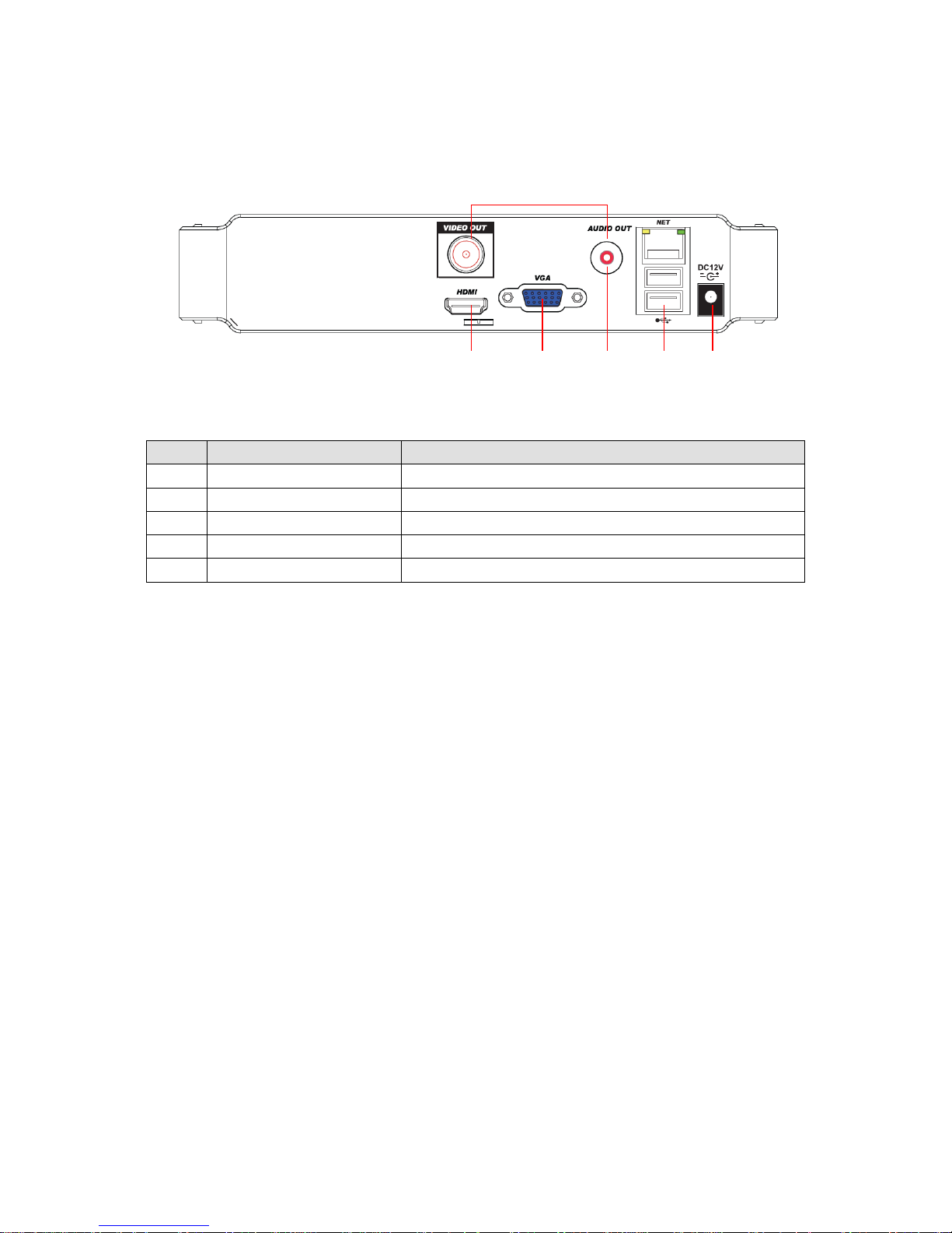
4.4 The Back Panel
5 3 1 2 4
4CH NVR Rear Panel Interfaces (Mini case)
Index
Name
Description
1
The video/audio output
The input interface of the audio signal
2
The network interface
The network interface of RJ-45
3
The VGA interface
The output interface of the VGA video signal
4
The power input
The power input interface
5
The HDMI interface
The output interface of the HDMI video signal

NVR User Manual
5 Basic Operations Guide
5.1 Power On and Off
5.1.1 Power On
Correctly install and power on the NVR. When the power indicator lit up,
the NVR will automatically start. The NVR will automatically detect hardware state of the
device during the starting. The booting process will continue for about 30 seconds. After boot,
the equipment
makes a beep sound and then enters the state of multi-screen real-time video surveillance.
5.1.2 Power Off
Press the power key for three seconds to achieve shutdown. Enter the [main menu]-
shutdown] and select [shutdown].
NVR User Manual
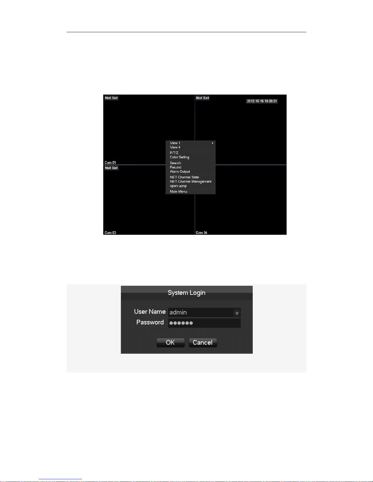
5.1 Preview and Login in
5.2.1 Preview
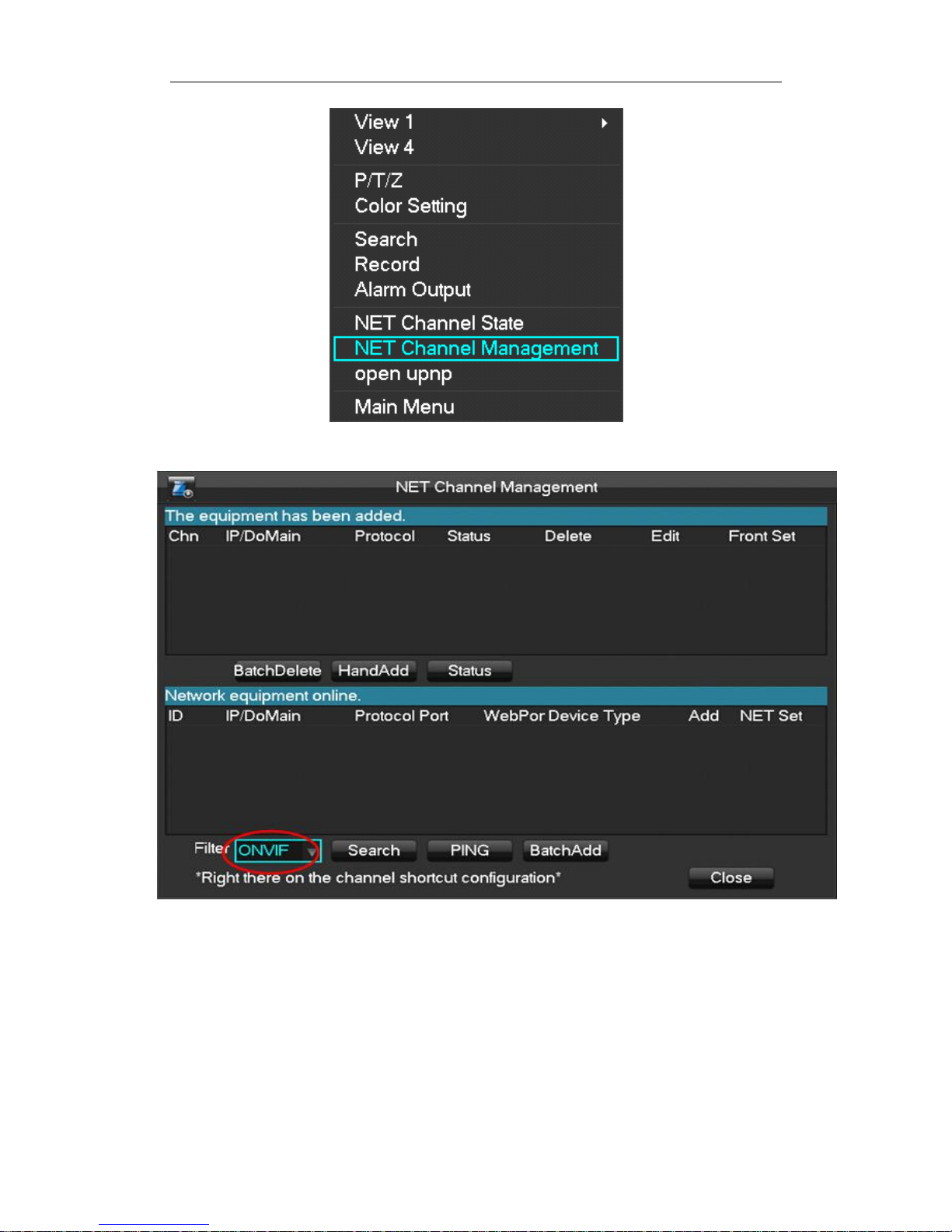
After the device is turned on, you will enter the real-time monitoring interface. Right click and the
following interface will pop up.
5.1.2 Login In
Click [main menu], and then input the username (default : admin) and the password of the
NVR (default : 123456 ) to complete the login.
NVR User Manual
5.4 IP Camera
5.4.1 Add IP Camera
Network channels are used to display remote IPCs. The addition of IPCs shows as the following
interface in 2 different methods: one way is an automatic method (UPNP), the other way is
manual bulk adding method.
Please make sure that the RJ45 port of NVR is connected to the router,and make sure the router
can distribute IP address to NVR and IPC using DHCP function.
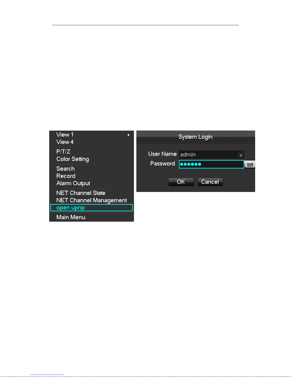
(1) Automatic method(UPNP)
Step 1:After the device is turned on, choose ’’open upnp’’, enter the user name: ”admin”
and password: “123456”. Click OK.
Step 2:System prompt” UPNP is turned on , it will automatically turn off after 10 minutes .”
Click OK ,system will automatically add IPC to all NVR channel. Right click USB mouse, choose
NET Channel Management, then you can find the added IPC information on ”the equipment has
been added “. The IPC MAC address of the added cameras will be listed under “Chn IP/DoMain”.
NVR User Manual
Remark: Status bar show green icon that means the IPC have been connected
successfully.
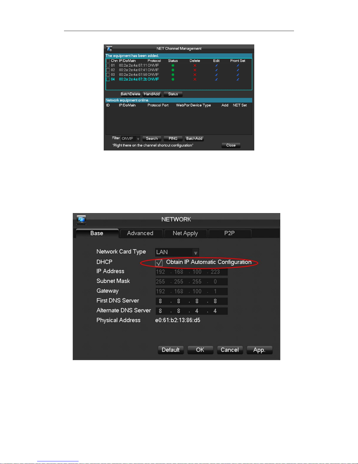
(2) Manual bulk adding mode
Step 1: Please make sure that ” DHCP” option on the NVR menu is checked it will prompts
“Obtain IP Automatic Configuration.”
Step2:Go back to “LIVE“ window,right click USB mouse and choose “NET Channel Management”.
NVR User Manual
Step 3: Choose “ONVIF” on the ”Filter” option.

NVR User Manual
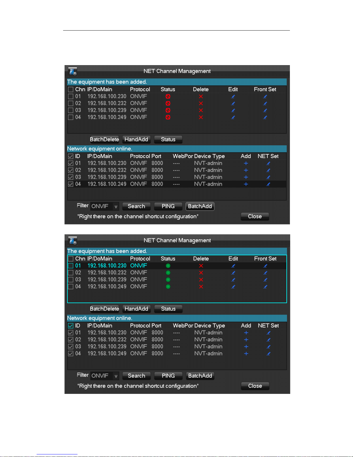
Step 4:Click “Search” to search the connected IPC.
Step 5:Check the need to add IPC, and click “BatchAdd” to add.
NVR User Manual
Step 6:Once adding camera is done, the added IPC list with IP address will be displayed under the
menu “the equipment has been added.”
Remark: Status bar show green icon that means the IPC have been connected
successfully.
NVR User Manual
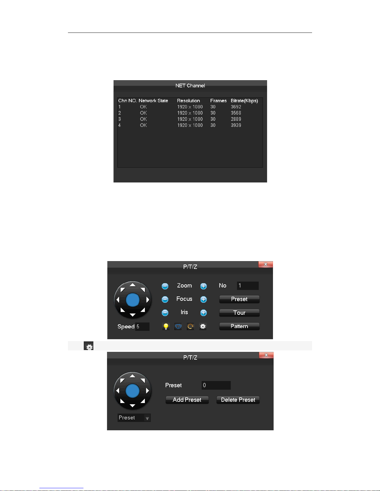
5.4.2 Status Display
Right click in the real-time monitoring screen and select [net channel] to view the status of the
network channels.
5.5 PTZ Control
Right click on the channel you wish to use the PTZ control, and select [PTZ] to enter the PTZ
interface. If access to a simulated PTZ controller is required, enter [Main Menu] - [PTZ] to modify
the PTZ protocol, the baud rate, and address bits. Then right click in the corresponding channel
and select [PTZ].The PTZ control interface is shown as the following interface.
Click to enter the PTZ configuration page.
Refer to 8.2 about more details.
 Loading...