

Page 1
iSMA-B-LP
User Manual
Modbus
Global Control 5 Sp. z o.o.
Warsaw, Poland
www.gc5.pl
Page 2

Table of contents
1 Introduction ................................................................................................................................................................... 5
1.1 Revision history ......................................................................................................................................................................... 5
1.2 Safety rules ................................................................................................................................................................................ 5
1.3 Technical specifications .......................................................................................................................................................... 6
1.4 Room Panel versions ............................................................................................................................................................... 7
...................................................................................................................................................................................................... 8
1.5 Dimensions ................................................................................................................................................................................ 8
2 Power supply and Communication ............................................................................................................................ 9
2.1 DC power connection ............................................................................................................................................................. 10
2.2 AC power connection ............................................................................................................................................................. 10
2.3 Connecting the communication bus (RS485) ................................................................................................................... 10
2.4 Connecting more Room Panels in the network ................................................................................................................ 11
2.5 RS485 network termination .................................................................................................................................................. 11
2.6 Connection by USB ................................................................................................................................................................. 12
3 Restoring the default settings .................................................................................................................................. 13
4 Main parameters ........................................................................................................................................................ 14
4.1 PANEL_PASSWORD (40028) ................................................................................................................................................ 14
4.2 SUBMENU_PROTECTION (40228) ...................................................................................................................................... 14
4.3 Communication parameters ................................................................................................................................................. 15
4.3.1 COUNTER_OF_RECEIVED_MESSAGES (30004) ............................................................................................................................. 15
4.3.2 COUNTER_OF ERROR_MESSAGES (30006) .................................................................................................................................... 15
4.3.3 COUNTER_OF_SENT_MESSAGES (30008) ...................................................................................................................................... 15
4.3.4 BAUD_RATE (40017)............................................................................................................................................................................. 15
4.3.5 STOP_BITS (40018) .............................................................................................................................................................................. 15
4.3.6 PARITY_BIT (40020) ............................................................................................................................................................................. 16
4.3.7 RESPONSE_DELAY_TIME (40021) ..................................................................................................................................................... 16
4.3.8 PANEL_ADDRESS (40023)................................................................................................................................................................... 16
4.3.9 PROTOCOL (40024) .............................................................................................................................................................................. 16
4.4 Time configuration ................................................................................................................................................................. 17
4.4.1 HOURS (40203) ..................................................................................................................................................................................... 17
4.4.2 MINUTES (40204) ................................................................................................................................................................................. 17
4.4.3 TIME_VISIBILITY (Register 40218, bit 0) .......................................................................................................................................... 17
4.4.4 ENTER_MENU_TIME (40223). ............................................................................................................................................................ 17
4.4.5 EXIT_EDIT_TIME (40224) ..................................................................................................................................................................... 17
4.4.6 EXIT_MENU_TIME (40225) .................................................................................................................................................................. 18
4.5 Device Configuration .............................................................................................................................................................. 18
4.5.1 VERSION_TYPE (30001) ...................................................................................................................................................................... 18
4.5.2 LIVE_TIME (30012) ................................................................................................................................................................................ 18
4.5.3 SENSORS (Register 30029, bits 0 - 2) ............................................................................................................................................... 18
4.5.4 DEVICE_ACTIONS (40001) .................................................................................................................................................................. 19
4.6 DEVICE CONFIGURATION REGISTER (40205) ................................................................................................................. 19
4.6.1 BEEPER (Register 40205, bit 0) .......................................................................................................................................................... 19
4.6.2 TIME_FORMAT (Register 40205, bit 1) ............................................................................................................................................. 19
4.6.3 BACKGROUND_ILLUMINATION_ LCD_ACTIVE (Register 40205, bit 3) ...................................................................................... 19
4.6.4 BACKGROUND_ILLUMINATION_KEY_PAD_ACTIVE (Register 40205, bit 4) ............................................................................ 19
4.6.5 CO2_IN_ALARM_FLASHING_LCD (Register 40205, bit 5) ............................................................................................................. 20
4.6.6 CO2_IN_ALARM_BUZZER (Register 40205, bit 6) ........................................................................................................................... 20
4.6.7 CO2_IN_ALARM_SHOW_HIGH (Register 40205, bit 7) ................................................................................................................... 20
4.6.8 SUBMENU_ICON_DISPLAY_OFF (Register 40205, bit 10) ............................................................................................................ 20
4.6.9 PANEL_OFF (Register 40205, bit 11) ................................................................................................................................................. 20
4.6.10 KEY_PAD_OFF (Register 40205, bit 12) ............................................................................................................................................ 20
4.6.11 LCD_FLASHING (Register 40205, bit 13) .......................................................................................................................................... 21
4.6.12 KEY_PAD_FLASHING (Register 40205, bit 14) ................................................................................................................................ 21
Page 3

iSMA-B-LP Room Panel/Modbus
version 1.3 www.gc5.pl Page 2 / 121
4.7 Room Panel Modes ................................................................................................................................................................ 21
4.8 LCD Display .............................................................................................................................................................................. 22
4.8.1 Icons displaying. .................................................................................................................................................................................... 22
4.8.1.1 LCD_ICON_DISPLAY (40219) ..................................................................................................................................................................... 23
4.8.1.2 LCD_ICON_FLASHING (40220) ................................................................................................................................................................. 23
4.8.1.3 LCD_ICON_FLASHING_TIME (40221) ...................................................................................................................................................... 24
4.8.1.4 SUBMENU_ICON_FLASHING (40229) ..................................................................................................................................................... 24
4.8.1.5 SUBMENUICON_FLASHING_TIME (40222) .............................................................................................................................................. 25
4.8.2 Main Menu display ................................................................................................................................................................................ 25
4.8.2.1 REFRESHING_TIME (40217) ..................................................................................................................................................................... 25
4.8.3 LCD_BACKGROUND_ILLUMINATION_SETTINGS ........................................................................................................................... 26
4.9 Key Pad ..................................................................................................................................................................................... 27
4.9.1 Menu button ........................................................................................................................................................................................... 27
4.9.2 OK button ................................................................................................................................................................................................ 27
4.9.3 Arrow buttons (up and down) ............................................................................................................................................................. 27
4.9.4 Key Pad Background Illumination Settings ...................................................................................................................................... 28
5 Sensors Configuration ............................................................................................................................................... 29
5.1 Temperature Sensor ............................................................................................................................................................... 29
5.1.1 TEMPERATURE_SENSOR_ACTUAL_VALUE (30301) ..................................................................................................................... 29
5.1.2 TEMPERATURE_SENSOR_OFFSET (40304) .................................................................................................................................... 30
5.1.3 TEMPERATURE_FILTER (40307) ....................................................................................................................................................... 30
5.1.4 TEMPERATURE_NAME (40310) ......................................................................................................................................................... 30
5.1.5 TEMPERATURE_CONFIGURATION (40316, bit 0 and bit 4) ......................................................................................................... 31
5.2 Humidity Sensor ...................................................................................................................................................................... 31
5.2.1 HUMIDITY_SENSOR_ACTUAL_VALUE (30302) ............................................................................................................................... 31
5.2.2 HUMIDITY_SENSOR_OFFSET (40305) ............................................................................................................................................. 31
5.2.3 HUMIDITY_FILTER (40308) ................................................................................................................................................................. 31
5.2.4 HUMIDITY_NAME (40312) ................................................................................................................................................................... 31
5.2.5 HUMIDITY_CONFIGURATION(Register 40317, bit 0 and bit 4) .................................................................................................... 32
5.3 CO2_SENSOR ........................................................................................................................................................................... 32
5.3.1 CO2_SENSOR_ACTUAL_VALUE (30303) ........................................................................................................................................... 32
5.3.2 CO2_SENSOR_OFFSET (40306) .......................................................................................................................................................... 32
5.3.3 CO2_FILTER (40309) ............................................................................................................................................................................. 33
5.3.4 CO2_NAME (40314) ............................................................................................................................................................................... 33
5.3.5 CO2_CONFIGURATION (40318, bit 0) ................................................................................................................................................ 33
5.3.6 CO2_SETPOINT_FOR_ALARM (40226) .............................................................................................................................................. 33
5.3.7 CO2_DIFFERENTIAL_FOR_ALARM (40227) ..................................................................................................................................... 33
6 Setpoint registers ....................................................................................................................................................... 34
6.1 SETPOINT_VALUE (41501) ................................................................................................................................................... 34
6.2 EFFECTIVE_SETPOINT (31502) ........................................................................................................................................... 34
6.3 DEFAULT_SETPOINT (41503) .............................................................................................................................................. 34
6.4 OFFSET_SETPOINT (41504) ................................................................................................................................................. 34
6.5 SETPOINT_LOW_LIMIT (41505) ........................................................................................................................................... 35
6.6 SETPOINT_HIGH_LIMIT (41506).......................................................................................................................................... 35
6.7 OFFSET_RANGE (41507) ...................................................................................................................................................... 35
6.8 SETPOINT_STEP (41508) ...................................................................................................................................................... 35
6.9 OFFSET_NAME (41509) ........................................................................................................................................................ 35
6.10 SETPOINT_NAME (41511) .................................................................................................................................................... 36
6.11 SETPOINT CONFIGURATION (41513) ................................................................................................................................ 36
6.11.1 SETPOINT_VISIBILITY (Register 41513, bit 0) ................................................................................................................................. 36
6.11.2 SETPOINT_EDITION (Register 41513, bit 1) ..................................................................................................................................... 36
6.11.3 OPERATING_MODE (Register 41513, bit 2) ...................................................................................................................................... 36
6.11.4 SETPOINT_DISPLAY (Register 41513, bit 3) .................................................................................................................................... 36
6.11.5 THIRD_POINT_ACTIVE (Register 41513, bit 4) ................................................................................................................................ 37
6.11.6 SETPOINT_FAST_EDIT_MODE (Register 41513, Bit 5) .................................................................................................................. 37
6.12 Setting setpoint ....................................................................................................................................................................... 38
Page 4

iSMA-B-LP Room Panel/Modbus
version 1.3 www.gc5.pl Page 3 / 121
6.12.1 Operating Mode is “true” (see Operating Mode) ............................................................................................................................. 38
6.12.2 Operating Mode is false (see Operating Mode ) .............................................................................................................................. 39
7 Fan Configuration Registers .................................................................................................................................... 40
7.1 FAN_CURRENT_SPEED (41601) ......................................................................................................................................... 40
7.2 FAN_MODE (41602) ............................................................................................................................................................... 40
7.3 FAN_TYPE (41603) ................................................................................................................................................................. 41
7.4 FAN_MODE_NAME (41604-41612)..................................................................................................................................... 42
7.5 FAN_CONFIGURATION (41614) .......................................................................................................................................... 42
7.5.1 FAN_CURRENT_SPEED_VISIBILITY (Register 41614, bit 0) ....................................................................................................... 42
7.5.2 FAN_EDITION (Register 41614, bit 1) ............................................................................................................................................... 42
7.5.3 PART_EDITABLE (Register 41614, Bit 2) ......................................................................................................................................... 42
7.5.4 FAN_CONFIG_FAST_EDIT_MODE (Register 41614, Bit 5) ........................................................................................................... 43
7.5.5 FAN_CONFIG_LOCAL_MODE (Register 41614, Bit 6) ................................................................................................................... 44
7.6 FAN_ICON_FLASHING_TIME (41615) ............................................................................................................................... 44
8 Occupancy Registers ................................................................................................................................................ 45
8.1 OCCUPANCY_CURRENT_STATUS (41701) ...................................................................................................................... 45
8.2 OCCUPANCY_MODE (41702)............................................................................................................................................... 45
8.3 OCCUPANCY_MODE_NAME (41703-41705) .................................................................................................................... 46
8.4 OCCUPANCY_CONFIGURATION (41707) .......................................................................................................................... 46
8.4.1 OCCUPANCY_VISIBILITY (Register 41707, bit 0) .......................................................................................................................... 46
8.4.2 OCCUPANCY_MODE_EDITION (Register 41707, bit 1) ................................................................................................................. 46
8.4.3 EDIT_MODE (Register 41707, Bit 5) .................................................................................................................................................. 46
8.4.4 OCCUPIED_CONFIG_LOCAL_MODE (Register 41707, Bit 6) ....................................................................................................... 47
9 Registers adjustable locally from the Room Panel .............................................................................................. 49
9.1 Configuration (CONF) ............................................................................................................................................................ 49
9.2 Device (DEV) ............................................................................................................................................................................ 50
9.3 Temperature (TEMP) ............................................................................................................................................................. 51
9.4 Humidity (HUM) ...................................................................................................................................................................... 51
9.5 CO2 (CO2) ................................................................................................................................................................................. 52
9.6 Setpoint (SETP) ...................................................................................................................................................................... 53
9.7 Fan (Fan) ................................................................................................................................................................................... 54
9.8 Occupancy (OCCU) ................................................................................................................................................................ 54
10 Main Menu user defined parameters. .................................................................................................................... 55
11 Submenus with user defined parameters.............................................................................................................. 55
11.1 Numeric parameter type registers ..................................................................................................................................... 55
11.1.1 XPresentValue (X = [1.8]) .................................................................................................................................................................... 56
11.1.2 XName (X = [1.8]) .................................................................................................................................................................................. 56
11.1.3 XPriority (X = [1.8]) ................................................................................................................................................................................ 56
11.1.4 XSTEP (X = [1.8]) ................................................................................................................................................................................... 56
11.1.5 XLowLimit (X = [1.8]) ............................................................................................................................................................................ 56
11.1.6 XHIGH_LIMIT (X = [1.8]) ....................................................................................................................................................................... 56
11.1.7 XConfiguration (X = [1.8]) .................................................................................................................................................................... 56
11.1.7.1 Visibility bit 0 ............................................................................................................................................................................................... 56
11.1.7.2 Editable bit 1 ............................................................................................................................................................................................... 57
11.1.7.3 First point Active bit 2 ............................................................................................................................................................................... 57
11.1.7.4 Second point Active bit 3 ......................................................................................................................................................................... 57
11.1.7.5 Third point Active bit 4 .............................................................................................................................................................................. 57
11.1.7.6 oC Unit Active bit 6 ...................................................................................................................................................................................... 57
11.1.7.7 F Unit Active bit 7 ....................................................................................................................................................................................... 57
11.1.7.8 Pa Unit Active bit 8 .................................................................................................................................................................................... 57
11.1.7.9 Lx Unit Active bit 9 ..................................................................................................................................................................................... 57
11.1.7.10 ppm Unit Active bit 10 ............................................................................................................................................................................ 57
11.1.7.11 m3h Unit Active bit 11 ............................................................................................................................................................................ 58
11.1.7.12 %Rh Unit Active bit 12 ............................................................................................................................................................................ 58
11.1.7.13 Ls Unit Active bit 13 ................................................................................................................................................................................ 58
Page 5

iSMA-B-LP Room Panel/Modbus
version 1.3 www.gc5.pl Page 4 / 121
11.1.7.14 % Unit Active bit 14 ................................................................................................................................................................................. 58
11.1.7.15 h Unit Active bit 15 .................................................................................................................................................................................. 58
11.2 Boolean parameter type registers ...................................................................................................................................... 58
11.2.1 XPresentValue (X = [1.8]) .................................................................................................................................................................... 58
11.2.2 XName (X = [1.8]) .................................................................................................................................................................................. 58
11.2.3 XTrueText (X = [1.8])............................................................................................................................................................................. 59
11.2.4 XFalseText (X = [1.8]) ........................................................................................................................................................................... 59
11.2.5 XPriority (X = [1.8]) ................................................................................................................................................................................ 59
11.2.6 XConfiguration (X = [1.8]) .................................................................................................................................................................... 59
11.2.6.1 Visibility bit 0 ............................................................................................................................................................................................... 59
11.2.6.2 Editable bit 1 ............................................................................................................................................................................................... 59
11.3 Submenu MenuActivePoints registers ............................................................................................................................. 60
11.4 Submenu Boolean All Present Value registers (40107 - 40113) ................................................................................... 60
12 List of all Modbus Registers .................................................................................................................................... 61
12.1.1 List of User defined parameters Modbus registers ...................................................................................................................... 68
12.1.2 Main Menu user defined parameters ............................................................................................................................................... 68
12.1.3 Temperature Submenu ........................................................................................................................................................................ 74
12.1.4 Fan Submenu ......................................................................................................................................................................................... 82
12.1.5 Light Submenu ...................................................................................................................................................................................... 90
12.1.6 Blind Submenu ...................................................................................................................................................................................... 98
12.1.7 Alarms Submenu ................................................................................................................................................................................ 106
12.1.8 Occupancy Submenu ......................................................................................................................................................................... 114
Page 6

iSMA-B-LP Room Panel/Modbus
version 1.3 www.gc5.pl Page 5 / 121
1 Introduction
1.1 Revision history
Rev
Date
Description
1.0
28.08.2016
First edition
1.1
21.02.2017
The reason for creation of new version of the document:
New function:
• Added SubmenuIconDisplayOFF bit in DeviceConfiguration register to
disable displaying of Submenu Icons;
Changes in Document:
• Added SubmenuIconDisplayOFF bit description in DeviceConfiguration
section
• Added description of Submenu Boolean All present Value registers
1.2
06.06.2017
Added information about BACnet MS/TP protocol
1.3
16.11.2017
Added new version of the Panel (iSMA-B-LP(-XX)-1)
Table 1 Revision history
1.2 Safety rules
Note: Incorrect wiring of this product can damage the product and lead to other hazards.
Make sure the product has been correctly wired before turning the power ON.
Before wiring or removing/mounting the product, be sure to turn the power OFF. Failure to
do so might cause an electric shock.
Do not touch electrically charged parts such as power terminals. Doing so might cause an
electric shock.
Do not disassemble the product. Doing so might cause an electric shock or faulty
operation.
Use the product within the operating ranges recommended in the specification (voltage,
shock, mounting direction, atmosphere etc.). Failure to do so might cause a fire or faulty
operation.
Firmly connect plugs to the terminals. Insufficient connection of the plugs might cause a
power failure and communication problems.
Page 7

iSMA-B-LP Room Panel/Modbus
version 1.3 www.gc5.pl Page 6 / 121
1.3 Technical specifications
Power supply
Voltage
24V AC/DC ± 20%
Power consumption
iSMA-B-LP(-1) 0.5 W (24 V DC), 0.75 VA
(24 VAC)
iSMA-B-LP-H(-1) 0.5 W (24 V DC), 0.75 VA
(24 VAC)
iSMA-B-LP-C(-1) 0.7 W (24 V DC), 1 VA (24 V AC)
iSMA-B-LP-HC(-1) 0.7 W (24 V DC), 1 VA
(24 V AC)
Built-in sensors
Temperature sensor
• 10k NTC type
• Accuracy: ±0.5˚C
• Range: 0 - 50˚C
• Resolution: ±0.1˚C
Humidity sensor
• Range: 0 – 100% RH
• Accuracy: ±2% RH in range 20 – 80% RH
• Resolution: ±1% RH
CO2 sensor
• Method Non Dispersive Infrared (NDIR),
gold plated optics, diffusion sampling (with
Telaire’s Patented ABC Logic Self Calibrated
Algorithm)
• Range: 400 – 2000 ppm
• Accuracy: ±30 ppm OR ±3% of
reading
• Stability: < 2% of FS over life of
sensor (15 years typical)
• Warm Up Time : < 2 minutes
(operational);
10 minutes (maximum accuracy)
• Calibration: ABC Logic Algorithm
• Manual Calibration Interval: Not
required
RS485 Interface
Communication protocols
Modbus RTU, Modbus ASCII, BACnet MS/TP
Baud rate
From 4800 to 115200 bps
USB
USB
Mini USB , Type B
Environment
Ingress Protection
IP40
Temperature
Storage
-40˚C to +85˚C
Operating
0˚C to +50˚C
Humidity
Relative
5% to 95%
Platform
ARM Cortex - M0+
Housing
• Construction: plastic, self-extinguishing
(PC/ABS)
• Wall mounting (standard electric box)
• Cooling: internal air circulation
Page 8

iSMA-B-LP Room Panel/Modbus
version 1.3 www.gc5.pl Page 7 / 121
Dimension
Width
100 mm
Length
27 mm
Height
123 mm
Table 2 Technical specification
1.4 Room Panel versions
There are four different sensors’ configuration options with which the Room Panel can be
equipped. According to presence of particular sensors, different parameters and settings
are available.
All possible sensors’ configuration versions are shown in the Table 3 below.
Ordering
Temperature
Humidity
CO2
iSMA-B-LP(-1)* ✓
iSMA-B-LP-H(-1)* ✓ ✓
iSMA-B-LP-C(-1)* ✓
✓
iSMA-B-LP-HC(-1)* ✓ ✓ ✓
Table 3 Room Panel Sensor Configuration versions
*There are two versions of keypad icons set available: standard and optional.
The ordering code for a standard keypad icons set panel version is iSMA-B-LP(-XX), and for
the optional icons set is iSMA-B-LP(-XX)-1.
iSMA-B-LP(-XX) iSMA-B-LP(-XX)-1
Page 9
iSMA-B-LP Room Panel/Modbus
version 1.3 www.gc5.pl Page 8 / 121
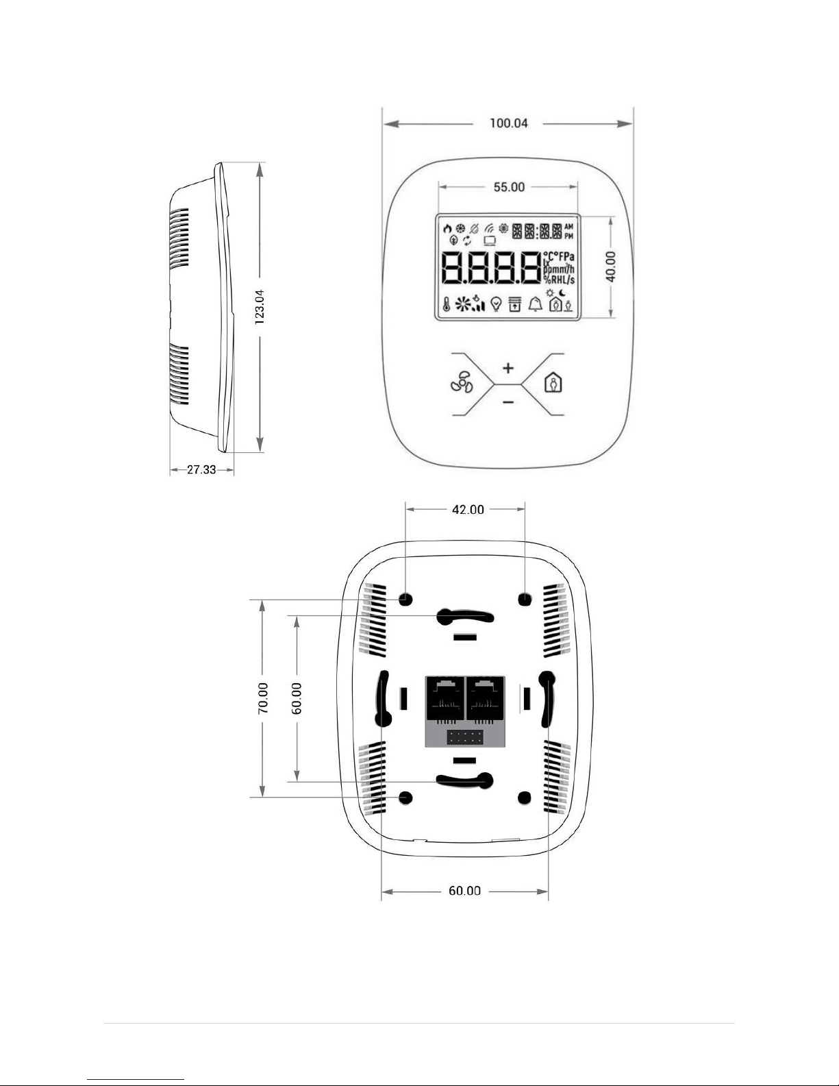
1.5 Dimensions
Figure 1 Room Panel iSMA-B-LP dimensions
Page 10
iSMA-B-LP Room Panel/Modbus
version 1.3 www.gc5.pl Page 9 / 121
2 Power supply and Communication
The Room Panel iSMA-B-LP can be powered with 24 V AC/DC. Power consumption
depends on power supply voltage type used and CO2 sensor presence (see Technical
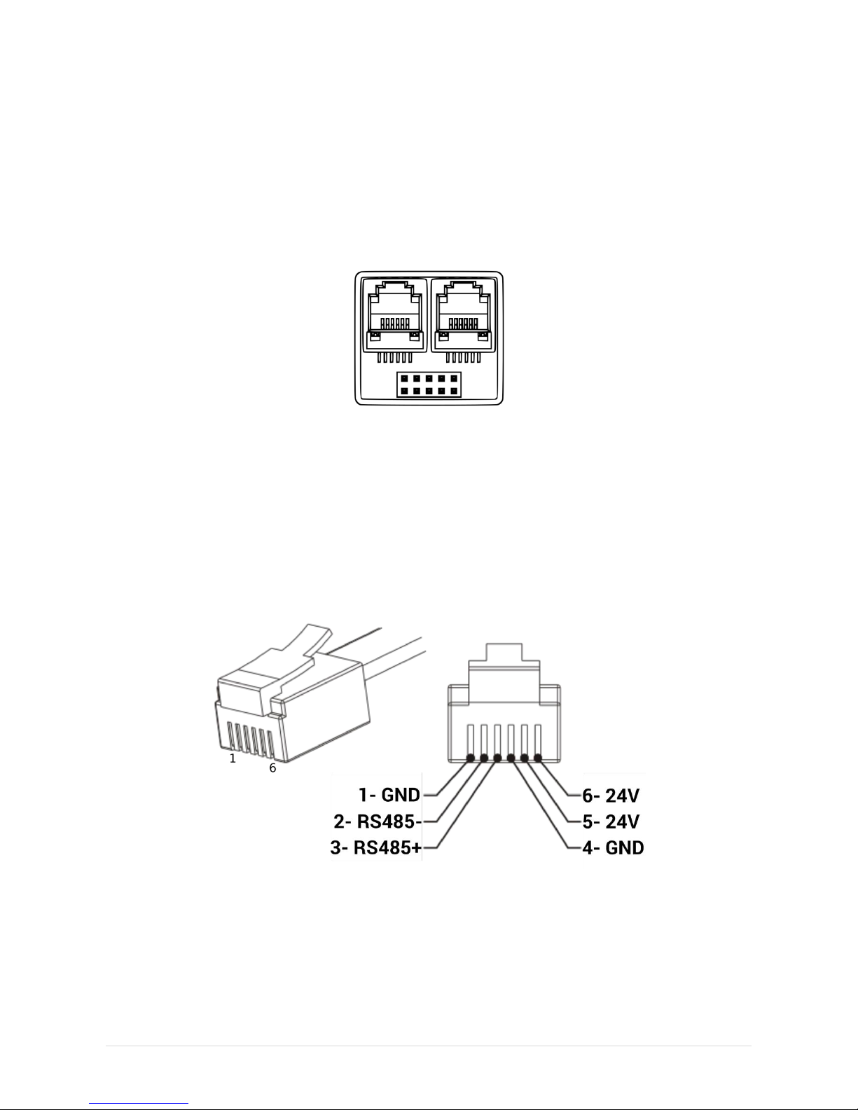
specification table). There are two RJ12 sockets mounted on the back side of the Room
Panel (Figure 2). Each RJ12 socket has the same internal connection and functionality.
Two RJ12 sockets allow for using in and out connections for other devices in the network.
Power supply can be connected through the RJ12 connector as shown in Figure 3 below.
Figure 2 RJ12 sockets in the back side of the Room Panel
There are two pairs of pins for 24 V AC/DC power supply connection (+24 V DC pins 5 and
6, -24 V DC pins 1 and 4). These pin pairs can be used freely. It is especially useful when
different types of connection cables are used (4 or 6 core). It is possible to use single
cable with RJ12 connectors for power supply and RS485 communication. Pins no. 2 and
3 are dedicated for RS485 communication connection. Communication bus should be
connected as shown in Figure 6.
The Room Panel exchanges data with other devices through Modbus protocol
(RTU/ASCII) and BACnet MS/TP.
Figure 3 RJ12 socket pin configuration
WARNING! With RS485 pay attention to standard polarization. Connect RS485+ to pin no. 3
and RS485- to pin no. 2 as shown in Figure 3 above.
Page 11
iSMA-B-LP Room Panel/Modbus
version 1.3 www.gc5.pl Page 10 / 121
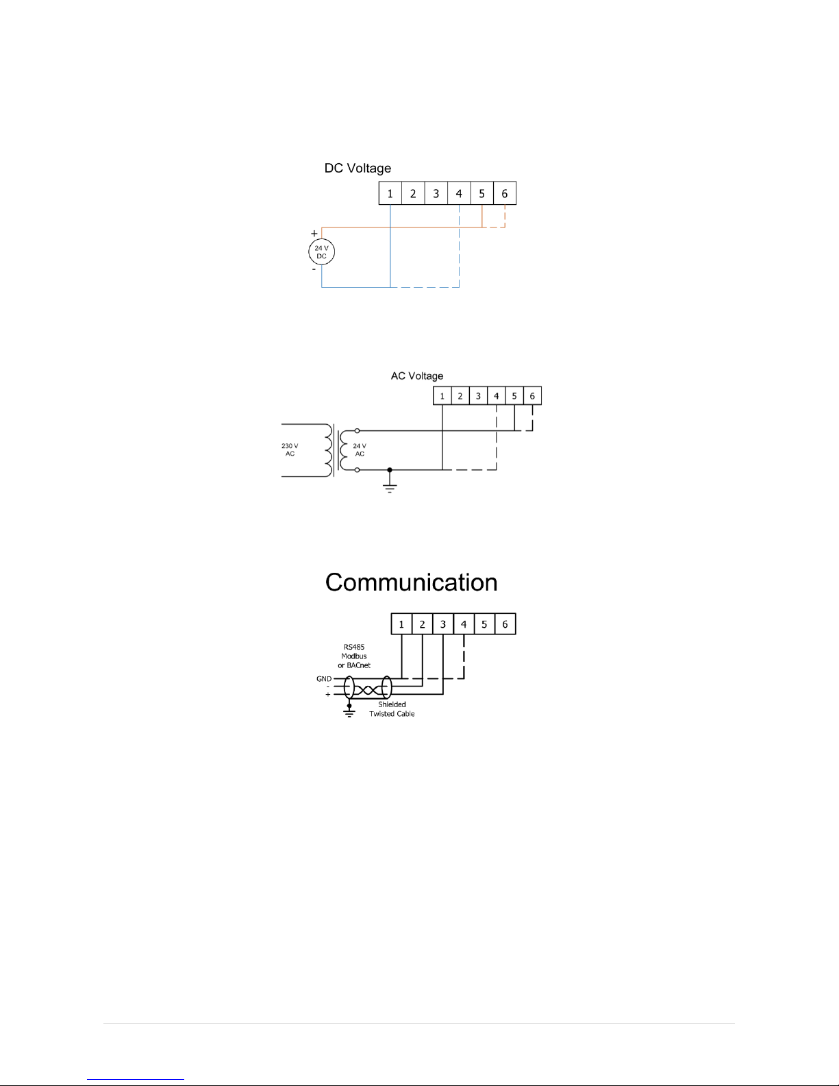
2.1 DC power connection
Figure 4 DC power supply connection
2.2 AC power connection
Figure 5 AC power supply connection
2.3 Connecting the communication bus (RS485)
Figure 6 RS485 connection
Page 12
iSMA-B-LP Room Panel/Modbus
version 1.3 www.gc5.pl Page 11 / 121
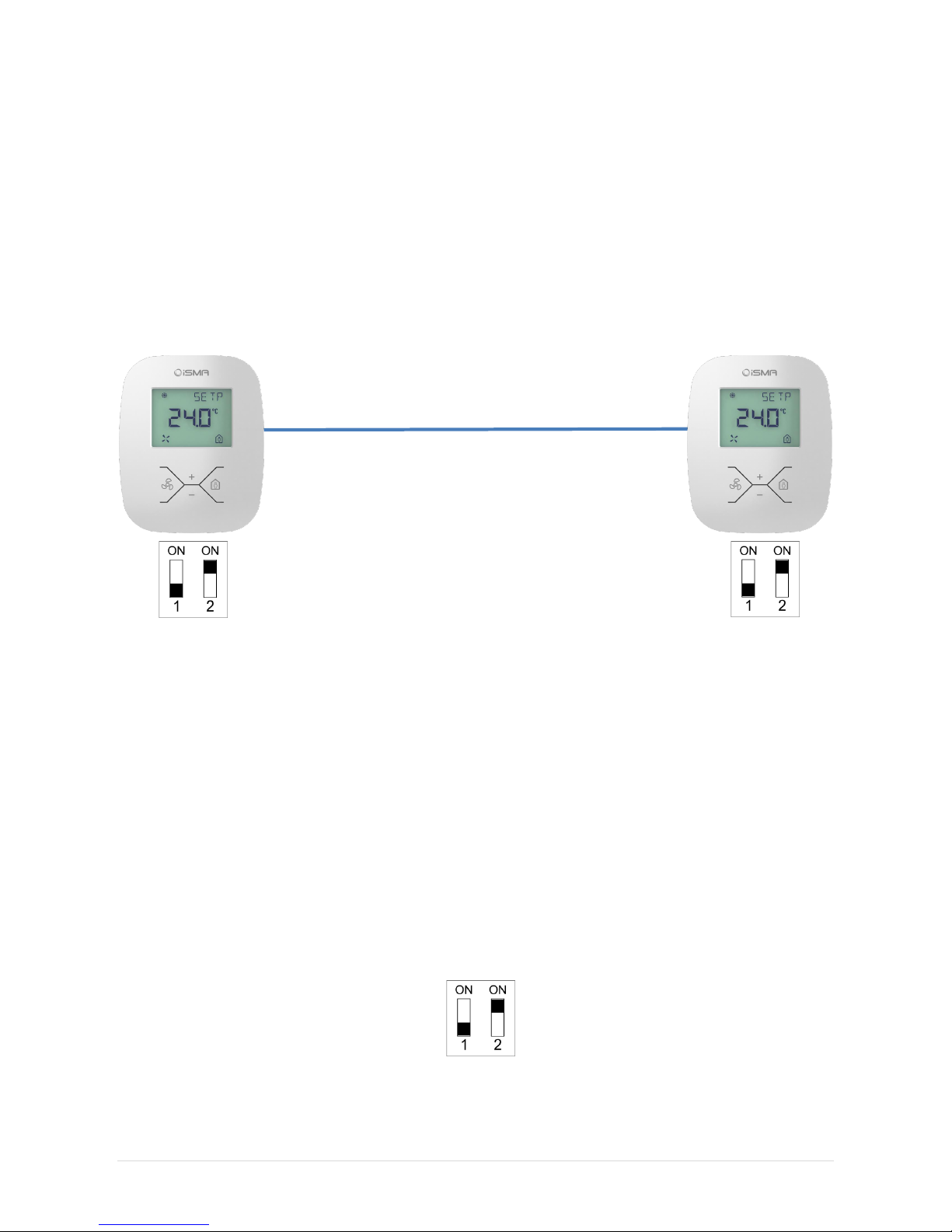
2.4 Connecting more Room Panels in the network
It is possible to connect more Room Panels into the one network in a very simple way.
Additional RJ12 socket can be used to connect another Room Panel by using one single
cable. Every panel can exchange information within the network. The solution can be
applied in large areas when more than one Room Panels are needed. Maximal number of
devices connected in one network is 128.
WARNING! First and last device in the network need to have termination activated (see
RS485 network termination)
Max. 128
RJ12 *** RJ12
First Room Panel in the network Last Room Panel in the network
Figure 7 Several Room Panels connection
2.5 RS485 network termination
The transmission line effects often present a problem on data communication networks.
These problems include reflections and signal attenuation.
To eliminate the presence of reflections from cable ends, the cable must be terminated at
both ends with a resistor across the line equal to its characteristic impedance. Both ends
must be terminated since the direction of propagation is bidirectional. In case of a RS485
twisted pair cable this termination is typically 120 Ω.
Each panel has in-built termination resistor which can be added to the network by setting
switch no. 2 in the DIP-switch to ON position. The last and first Room Panels in the
network need to have termination activated.
Figure 8 Connecting termination resistor by Switch no. 2
Page 13

iSMA-B-LP Room Panel/Modbus
version 1.3 www.gc5.pl Page 12 / 121
2.6 Connection by USB
USB connection is dedicated for maintenance and settings.
USB port (mini type B) is located at the bottom of the device (Figure 9).
Figure 9 Mini-USB port
USB connection provides Power Supply for the Room Panel (+5 V DC) so there is no need
for additional power supply in this connection type.
Figure 10 Mini-USB port pinout
Page 14
iSMA-B-LP Room Panel/Modbus
version 1.3 www.gc5.pl Page 13 / 121
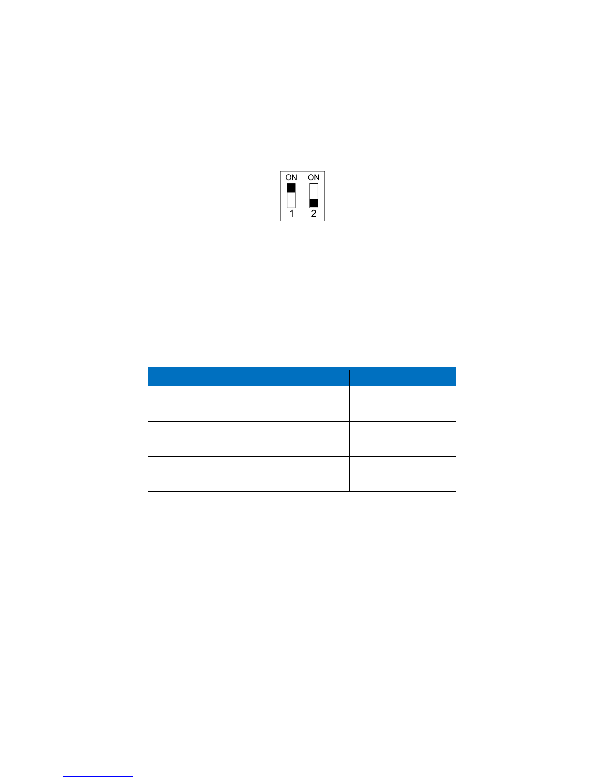
3 Restoring the default settings
To restore the default configuration of all registers, follow the below steps:
1. Turn power supply OFF
2. Set switch no. 1 on the DIP-switch to ON position.
Figure 11 Switch no. 1 position for default setting restore procedure
3. Turn power supply ON, LCD display starts blinking.
4. Set switch no. 1 on the DIP-switch to OFF to restore the default settings. To cancel
the reset, turn the power off and set switch no. 1 on the DIP-switch to OFF.
Default communication settings:
Register Name
Default Value
BAUD RATE
11520 (115200 bps)
STOP BITS
1
DATA BITS
8
PARITY BITS
0
ADDRESS
1
PROTOCOL
0 (Modbus RTU)
Table 4 Default communication settings.
Page 15

iSMA-B-LP Room Panel/Modbus
version 1.3 www.gc5.pl Page 14 / 121
4 Main parameters
iSMA-B-LP is a wall panel with 2.3” LCD display and four function buttons. Additionally, the
panel has the in-built temperature sensor and optionally the humidity and CO2 sensors.
iSMA-B-LP is powered with 24 V AC/DC and has the in-built RS485 port (Modbus
RTU/ASCII) and BACnet MS/TP. Use of open communication protocol allows to connect
the panel with any controller which supports Modbus RTU/ASCII or BACnet MS/TP.
Together with iSMA-B-FCU controller, the panel allows to change the basic parameters
such as: temperature setpoint, fan speed, FCU mode and other. Thanks to in-built USB
port, there is possibility of updating firmware and panel configuration without the
necessity of power supply. iSMA-B-LP has modern design and is available in different
colours (white is basic), on client’s request.
4.1 PANEL_PASSWORD (40028)
The register has password which is necessary to enter submenus and configuration
menus locally from the Room Panel (PIN code). Default password is 1000.
4.2 SUBMENU_PROTECTION (40228)
After activation of the particular bit of the register set, a password protects access to
different Submenu Editions (see table below).
The function allows for block changing of parameters inside each Submenu. It can be
useful especially in areas where Room Panel is vulnerable and subject to unauthorized
interaction (common areas).
In default setting all bits are inactive (access to each submenu unprotected).
Register bit
number
Name
Inactive state
Active state
Submenu
protection
0
Temperature
OFF(def)
ON
Temperature
Submenu
1
Fan
OFF(def)
ON
Fan Submenu
2
Light
OFF(def)
ON
Light Submenu
3
Blind
OFF(def)
ON
Blind Submenu
4
Alarms
OFF(def)
ON
Alarms Submenu
5
Occupancy
OFF(def)
ON
Settings Submenu
Table 5 Submenu Protection register structure
Page 16

iSMA-B-LP Room Panel/Modbus
version 1.3 www.gc5.pl Page 15 / 121
4.3 Communication parameters
4.3.1 COUNTER_OF_RECEIVED_MESSAGES (30004)
32-bit register with the number of valid Modbus messages received by the Room Panel
from the time of the last power-up. The value is reset after power cycle or after changing
of transmission parameters (speed, stop bits, parity, etc.).
4.3.2 COUNTER_OF ERROR_MESSAGES (30006)
32-bit register with the number of error Modbus messages received by the Room Panel
from the time of the last power-up. The value is reset after power cycle or after changing
of transmission parameters (speed, stop bits, parity, etc.).
4.3.3 COUNTER_OF_SENT_MESSAGES (30008)
32-bit register with the number of Modbus messages sent by the Room Panel from the
time of the last power-up. The value is reset after power cycle or after changing
transmission of parameters (speed, stop bits, parity, etc.).
4.3.4 BAUD_RATE (40017)
Actual baud rate in bps divided by 10. By default: 11520 (115200bps).
Table 6 Baud rate
4.3.5 STOP_BITS (40018)
Number of stop bits is determined on the basis of this register in accordance with the
following table:
Value
No of stop bits
1
1(default)
2
2
Table 7 Stop bits
Value
Baud rate
480
4800
960
9600
1920
19200
3840
38400
5760
57600
11520
115200(def)
Page 17
iSMA-B-LP Room Panel/Modbus
version 1.3 www.gc5.pl Page 16 / 121
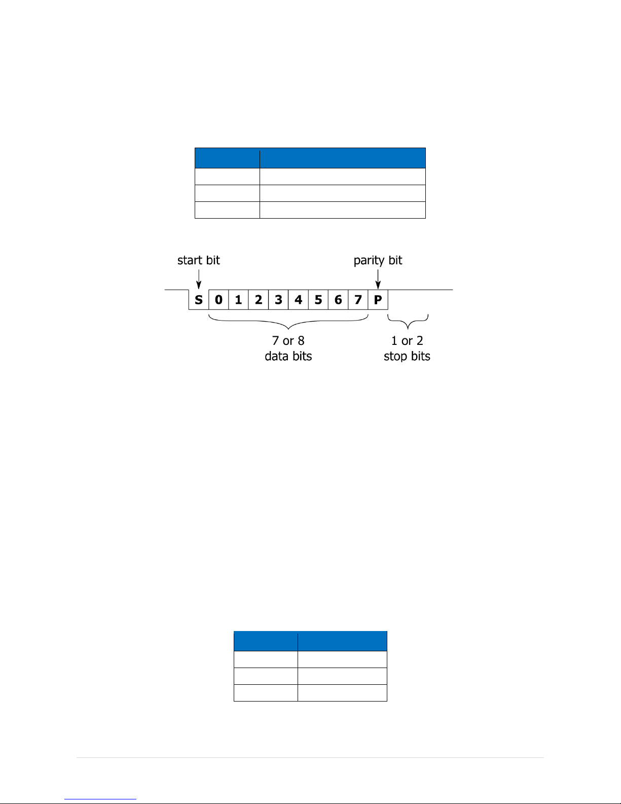
4.3.6 PARITY_BIT (40020)
Each byte of data being transferred may have additional protection as a parity bit added
before stop bit (bits).
The method of calculating parity bit determines the below table:
Register value
Type of parity bit
0
None(def)
1
Odd (number of all ones in a byte is odd)
2
Even (number of all ones in a byte is even)
Table 8 Parity bit
Figure 12 Modbus message frame
4.3.7 RESPONSE_DELAY_TIME (40021)
The value of this 16-bit register determines the number of milliseconds to wait before the
unit answers the question. This time is used to extend the interval between the question
and the answer.
The default value of 0 means no delay (the answer is sent once during the 3.5 character
required by the protocol Modbus RTU).
4.3.8 PANEL_ADDRESS (40023)
This register contains information about the Modbus address of the Room Panel.
Default address is 1.
4.3.9 PROTOCOL (40024)
The register is responsible for protocol selection. Protocol is determined according to the
register value as shown in the following table:
Value
Action
0
Modbus RTU(def)
1
Modbus ASCII
2
BACnet MS/TP
Table 9 Protocol selectio
Page 18

iSMA-B-LP Room Panel/Modbus
version 1.3 www.gc5.pl Page 17 / 121
4.4 Time configuration
The time (if activated) is displayed on the 14-segment display block. After restart of the
device clock is not displayed. It starts to be visible after the Room Panel receives first
message with correct time value.
Figure 13 14-segment displays block for time displaying
4.4.1 HOURS (40203)
The register contains actual hour value in time displaying mode. 12h/24h mode is
determined by DEVICE_CONFIGURATION register (in default 24 h). When the clock is set
in 12h format, icons AM and PM are displayed automatically. A semicolon which
separates hours and minutes section flashes with 1 Hz frequency.
4.4.2 MINUTES (40204)
The register contains actual minute value in time displaying mode.
4.4.3 TIME_VISIBILITY (Register 40218, bit 0)
Bit 0 of the 40218 register determines the time visibility. If bit 0 is true, clock is visible in
Main Menu (it starts to be visible when the Room Panel receives first message with
correct time value after panel restart or connection of power supply). The clock is
displayed on 14-segment display block when the name of active parameter (visible) is
empty (each character in the parameter name is NULL). Default value is „true” (visible).
4.4.4 ENTER_MENU_TIME (40223).
When the Menu button is pushed longer than time value stored in the ENTER_MENU_TIME
register the user enters Submenu Edit Mode.
When the Menu button is pushed together with OK button longer than time value stored in
the ENTER_MENU_TIME register the user enters Settings Submenu Edit Mode. This
register has min. value 1 min. Default value is 2 sec.
4.4.5 EXIT_EDIT_TIME (40224)
The register contains the time after which edition of any editable parameter is finished.
Time starts after the last Key Pad activation (pushing any button during Edit Mode). This
register has min. value 1 min. Default value is 5 sec.
Hours section
Minutes section
Page 19

iSMA-B-LP Room Panel/Modbus
version 1.3 www.gc5.pl Page 18 / 121
4.4.6 EXIT_MENU_TIME (40225)
The register contains the time value after which Submenu Edit mode and Settings
Submenu Edit mode is finished and the device leads the user back to the Main Menu
displaying. Time starts after the last Key Pad activation (pushing any button). This
register has min. value 1 min. Default value is 10 sec.
4.5 Device Configuration
4.5.1 VERSION_TYPE (30001)
In this register are encoded type and firmware version of module.
High byte contains information about the type (Room Panel has a version 11110(0x6F16)
or 23910(0xEF16) when the device stays in bootloader).
Low byte contains the module firmware version multiplied by 10 (0x0A
16
= 10
10
means
firmware in version 1.0).
An example:
In register 30001 is number 267110 = 0x0A6F16. This means that it is a Room Panel with
firmware in version 1.0 (0x0A
16
= 1010).
4.5.2 LIVE_TIME (30012)
This 32-bits register contains information in seconds about “UP time”. After power supply
failure or the Panel restart Live time register value resets and the “UP time ” counts again.
4.5.3 SENSORS (Register 30029, bits 0 - 2)
The s ensors configuration which are already built-in in the Room Panel is encoded in the
3 first bits of the register Particular bit activity indicate which sensor is in-built (see table
below).
Register bit
number
Inactive state
Active state
Submenu
protection
0
No sensor
Built-in
Temperature Sensor
1
No sensor
Built-in
CO2 sensor
2
No sensor
Built-in
Humidity sensor
Table 10 Sensors configuration
Page 20

iSMA-B-LP Room Panel/Modbus
version 1.3 www.gc5.pl Page 19 / 121
4.5.4 DEVICE_ACTIONS (40001)
Setting register 40001 according to the table below enables 1 of 4 available actions: reset
device, reload settings, reset settings or enter bootloader.
Register
value decimal
Register value
hexadecimal
Action
511
0x01FF
Reset
767
0x02FF
Reload settings
1023
0x03FF
Reset settings
1279
0x04FF
Enter bootloader
Table 11 Device actions
4.6 DEVICE CONFIGURATION REGISTER (40205)
4.6.1 BEEPER (Register 40205, bit 0)
Bit 0 of register 40205 activates/deactivates the Beeper. When the beeper is active any
single pushing any button is signalized by the beeper sound. In addition, the beeper can
be also used for CO2 Alarm signalization. By default the beeper is active (bit 1 is „true”).
4.6.2 TIME_FORMAT (Register 40205, bit 1)
Bit 1 of register 40205 defines time format display. When bit is „true”, time is set in 12h
format. Otherwise time is displayed in 24h format (default).
When the clock is set in 12h format and it receives hours value in 24h format, icons AM
and PM are displayed according to calculation. A semicolon which separates hours and
minutes section in the clock flashes with 1 Hz frequency.
4.6.3 BACKGROUND_ILLUMINATION_ LCD_ACTIVE (Register 40205, bit 3)
Bit 3 of register 40205 switches on LCD background illumination. When bit is „true”, LCD
display is illuminated with intensity according to values stored in registers dedicated for
particular Room Panel modes. When the bit is “false” LCD display is not illuminated in any
mode. By default bit is “true”.
4.6.4 BACKGROUND_ILLUMINATION_KEY_PAD_ACTIVE
(Register 40205, bit 4)
Bit 4 of register 40205 switch on key pad background illumination When bit is „true” Key
Pad is illuminated with intensity according to values stored in registers dedicated for
particular Room Panel modes. When the bit is “false” Key Pad is not illuminated in any
mode. By default bit is “false” (Key Pad not illuminated).
Page 21

iSMA-B-LP Room Panel/Modbus
version 1.3 www.gc5.pl Page 20 / 121
4.6.5 CO2_IN_ALARM_FLASHING_LCD (Register 40205, bit 5)
Bit 5 of register 40205 switch on function LCD background illumination flashing when
CO2 alarm occur. When bit 5 is “true” CO2 Alarm is indicated by LCD display flashing.
Read more about CO2 Alarm in CO2 sensor. By default bit is “false” (function
deactivated).
4.6.6 CO2_IN_ALARM_BUZZER (Register 40205, bit 6)
Bit 6 of register 40205 switch on buzzer when CO2 alarm occur. When bit 6 is “true” CO2
Alarm is indicated by the beeper which emits sound with 1 Hz frequency. Read more
about CO2 Alarm in CO2 sensor. By default bit is “false” (function deactivated).
4.6.7 CO2_IN_ALARM_SHOW_HIGH (Register 40205, bit 7)
Bit 7 of register 40205 switch on “HIGH” label on display when CO2 alarm occur. When bit
7 is “true” and CO2 Alarm is active LCD display shows CO2 sensor actual value on 8segment displays block and blinking text “HIGH” on 14-segment displays block. By default
bit is “false” (function deactivated).
4.6.8 SUBMENU_ICON_DISPLAY_OFF (Register 40205, bit 10)
Bit 10 of register 40205 switch off submenu icon display. When bit 10 is “true” all
submenu icons are hidden, even in the case when one or more submenus contain active
points. The user can enter active submenu (with at least one active point) and proceed
normal operation , but its icon is invisible in the Mail Menu display view.
4.6.9 PANEL_OFF (Register 40205, bit 11)
Bit 11 of register 40205 switch off panel. When bit 11 is “true” the Room Panel is inactive.
It means that it is impossible to control The Room Panel locally (access to submenus and
parameters configuration is blocked – Key Pad is deactivated). LCD display and
background illumination are also OFF. The main menu is not displayed. The Room Panel
works as temperature sensor (or multisensor if CO2 sensor or humidity sensor are builtin). When the bit 12 is “false” the Room Panel works in normal mode (functions for local
control are active). By default bit is “false” (Panel ON).
4.6.10 KEY_PAD_OFF (Register 40205, bit 12)
Bit 12 of register 40205 switch off panel key pad. When bit 12 is active Key Pad function
is deactivated. Single pushing any button emits beeper sound (if beeper is activated) and
activates the Active Mode (set background illumination level) but submenu access is
blocked (it is impossible to enter any Menu and to change any parameters and settings).
Page 22

iSMA-B-LP Room Panel/Modbus
version 1.3 www.gc5.pl Page 21 / 121
The Main Menu is displayed. By default bit is “false” (Key Pad ON).
4.6.11 LCD_FLASHING (Register 40205, bit 13)
Bit 13 of register 40205 is responsible for LCD display flashing activation. When the bit 13
is „true”, LCD display flashes with the frequency stored in LCDIconFlashing register.
Flashing brightness level changes from 0% to maximum value from the registers:
BACKGROUND ILLUMINATION LCD FOR ACTIVE MODE register
BACKGROUND ILLUMINATION LCD FOR IDLE MODE register
BACKGROUND ILLUMINATION LCD FOR STANDBY MODE register
By default bit is “false” (LCD flashing inactive).
4.6.12 KEY_PAD_FLASHING (Register 40205, bit 14)
Bit 14 of register 40205 is responsible for Key Pad flashing activation. When the bit 14 is
“true”, Key pad flashes with the frequency stored in LCDIconFlashing register. Flashing
brightness level changes from 0% to maximum value from the registers:
BACKGROUND ILLUMINATION KEY PAD FOR ACTIVE MODE register
BACKGROUND ILLUMINATION KEY PAD FOR IDLE MODE register
BACKGROUND ILLUMINATION KEY PAD FOR STANDBY MODE register
By default bit is “false” (Key Pad flashing inactive).
4.7 Room Panel Modes
The Room Panel has 3 different modes:
• Active mode
• Idle mode
• Stand-by mode
The differences between particular modes are physically visible when all conditions below
are fulfilled:
1. Bit 11 of the DEVICE_CONFIGURATION register is “true” (Panel is ON).
2. Bit 4 of the DEVICE_CONFIGURATION register is “true” (Key Pad illumination active).
3. Bit 3 of the DEVICE_CONFIGURATION register is “true” (LCD illumination active).
4. There are different values in the registers responsible for Illumination level of different
modes (see LCD Background Illumination Settings and Key Pad Background Illumination
Settings).
Each mode determinates LCD and Key Pad background Illumination intensity.
Actual Room Panel mode depends on Key Pad activity (pushing buttons) and time values set
by appropriate registers. User can also control illumination intensity of each mode by
Page 23
iSMA-B-LP Room Panel/Modbus
version 1.3 www.gc5.pl Page 22 / 121
entering appropriate values to assigned registers.
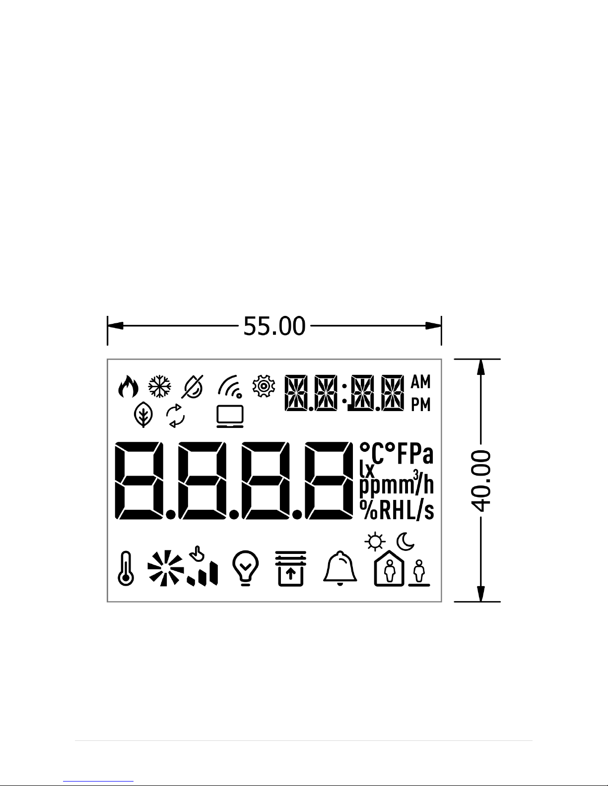
4.8 LCD Display
The Room Panel iSMA-B-LP is equipped with 2.3” LCD display with backlight.
By default LCD display is turned ON (when the device is powered) and basic parameters
from in-built sensors together with user defined parameters are shown in the Main Menu.
The register DEVICE_CONFIGURATION bit 11 is responsible for LCD display and Key Pad
activation.
When the bit is “false”, LCD display and Key Pad work in normal mode (parameters and
actual sensor values are displayed, submenus are visible and editable etc.).
If the bit is “true”, LCD display and Key Pad is deactivated. The Room Panel works as a
simple sensor. (CO2 sensor, temperature sensor, humidity sensor – depending on Room
Panel version, see table 3).
Figure 14 LCD display general view
4.8.1 Icons displaying.
There are many different Icons which are available on the Panel Display. User can choose
which Icon is dedicated for visualization of a particular process. Every single Icon can be
controlled by a higher level system. There are two Modbus registers which are responsible
Page 24
iSMA-B-LP Room Panel/Modbus
version 1.3 www.gc5.pl Page 23 / 121
for Icon Indication.
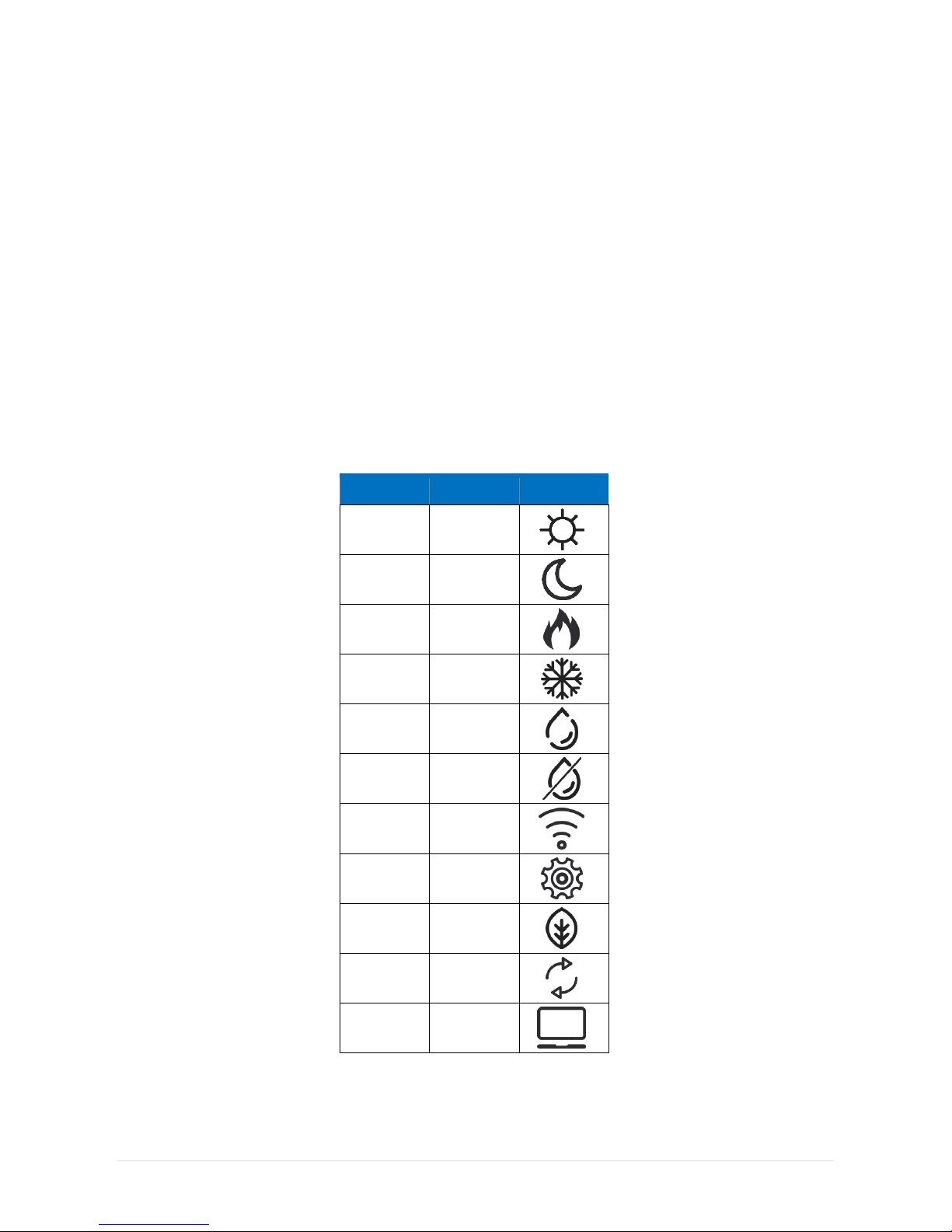
4.8.1.1 LCD_ICON_DISPLAY (40219)
Each bit of the register is responsible for displaying a particular icon.
Setting true value for single bit displays appropriate icon which is assigned to that bit
according to Table no. 12 below. By default, all icons are hidden (all bits of the register are
“false”).
4.8.1.2 LCD_ICON_FLASHING (40220)
Each bit of the register switches on blinking of particular Icons.
Setting true value for a particular bit causes blinking of a single Icon which is assigned to
that bit according to Table no. 12 below.
Bit
Icon Name
Icon
0
Sun 1
Moon
2
Heating 3
Cooling 4
Humidfire
5
Dehumidfire
6
Wireless
7
Settings
8
Eco 9
Recirculation
10
PC
Table 12 LCD Icon Display
Page 25

iSMA-B-LP Room Panel/Modbus
version 1.3 www.gc5.pl Page 24 / 121
4.8.1.3 LCD_ICON_FLASHING_TIME (40221)
It is possible to set Icon blinking frequency. Register LCD_ICON_FLASHING_TIME stores the
time which constitutes the base for calculating Icon blinking frequency. This register has
min. value of 50 ms. Default value is 500 ms (the icons are visible fo 500 ms and hidden for
500/4=125 ms).
4.8.1.4 SUBMENU_ICON_FLASHING (40229)
Each bit of the register switches on blinking of particular Icons.
Setting true value for a particular bit causes blinking of a single Icon which is assigned to
that bit according to Table no. 13 below.
Table 13 Submenu Icon Display
Bit
Icon Name
Icon
0
Temperature
1
Fan 1
2
Fan 2
3
Fan 3
4
Fan 4
5
Fan 5 6
Fan 6
7
Light 8
Blind 9
Alarms
10
Occupancy 1
11
Occupancy 2
12
Occupancy 3
Page 26

iSMA-B-LP Room Panel/Modbus
version 1.3 www.gc5.pl Page 25 / 121
4.8.1.5 SUBMENUICON_FLASHING_TIME (40222)
The Submenu Icons light up according to the status of assigned process. These icons are
not editable, however the user can choose if each submenu icon is to be visible or not.
Register SUBMENU_ICON_FLASHING_TIME stores the time which constitutes the base for
calculating a frequency of submenu icons’ flashing. This register has min. value of 50 ms.
Default value is 1000 ms (the icons are visible for 1000 ms and hidden for 1000/4=250 ms).
4.8.2 Main Menu display
Main part of the display shows current sensor values, the setpoint value and user defined
parameters with assigned units. The user can determine, whether a particular actual sensor
value or the actual setpoint value is to be shown or not. Chosen values are displayed one
after another repeatedly.
4.8.2.1 REFRESHING_TIME (40217)
Duration of display time of the particular parameter can be set in REFRESHING_TIME
register. When Refreshing Time elapses, the next parameter is displayed according to the
sequence of parameters display. Default value is 2 sec. (each parameter is displayed for 2
seconds). This register has min. value of 1 minute.
Sequence of parameters display:
1. Actual value of temperature sensor (if active)
2. Actual value of humidity sensor (if active)
3. Actual value of CO
2
sensor (if active)
4. Temperature Setpoint (if active)
5. User defined parameter with the highest priority
6. ………………….………………
7. User defined parameter with the lowest priority
The parameters are shown on 8-segment display block according to the type of the
parameter:
1. For Numeric type parameter – value of the parameter and the unit (defined by user) is
displayed.
2. For Boolean type parameter – text (defined by user) which corresponds to actual logic
state is displayed.
After Room Panel restart, user defined parameters are not displayed until they become
overwritten from a higher level system (Master Controller). If only one parameter is active, its
value is refreshed with interval stored in REFRESHING_TIME register.
Page 27

iSMA-B-LP Room Panel/Modbus
version 1.3 www.gc5.pl Page 26 / 121
If one or more user defined parameters have the same priority, register with the lowest
address is displayed first.
In the upper right corner of the display there are four 14-segment displays dedicated for the
clock, submenu and parameters’ names. These names are stored in the special Submenu
registers as a ASCII code values corresponding to the following characters (from the left
side) of the submenu name. In case when a character value equals 010=0x0016(NULL), the
character is hidden (not displayed). If all characters of particular parameter name are NULL
then the clock is displayed (if active).
4.8.3 LCD_BACKGROUND_ILLUMINATION_SETTINGS
When one of four keypad buttons is pressed, the Room Panel changes its state into Active
mode.
The same situation happens when the power supply is reconnected or after the Room Panel
restart.
In case when there is no keypad activity and the Room Panel stays ON, the subsequent
Background illumination modes activate. LCD display illuminates only when a value of the
register bit DEVICE_CONFIGURATION bit 3 is “true”. If not, LCD display is never illuminated.
Particular modes activate sequentially according to the following sequence:
1. Active – the mode activates after pushing any keypad buttons or after restart of the
Room Panel. LCD display illuminates with a brightness level stored in
BACKGROUND_ILLUMINATION_LCD_FOR_ACTIVE_MODE register. In default setting, the
value of Illumination for the active mode is 60%. It means that the display illuminates
with 60% of the maximum possible brightness. The LCD display stays in Active mode for
as long as it is determined in BACKGROUND_ILLUMINATION_LCD_TIME_TO_IDLE
register. The register contains time value in seconds (in default 10 sec) and the time
countdown starts with activation of the Active mode . It means that pressing any of the
keypad buttons resets the timer and countdown starts again.
2. Idle – the mode becomes active always after Active mode (Time to Idle is up). The
display illuminates with a brightness level stored in
BACKGROUND_ILLUMINATION_LCD_FOR_IDLE_MODE register (in default 40%). The
display stays in Idle mode during the time stored in
BACKGROUND_ILLUMINATION_LCD_TIME_TO_STANDBY register (in default 5 sec).
3. Standby – the mode becomes active always after Idle mode (Time to Standby is up). The
display illuminates with a brightness level stored in
BACKGROUND_ILLUMINATION_LCD_FOR STANDBY MODE register (in default 0%). The
display stays in Standby mode for as long as Active mode is not initiated.
Actual LCD display brightness level value is stored in
BACKGROUND_ILLUMINATION_LCD_CURRENT_VALUE register.
Page 28
iSMA-B-LP Room Panel/Modbus
version 1.3 www.gc5.pl Page 27 / 121
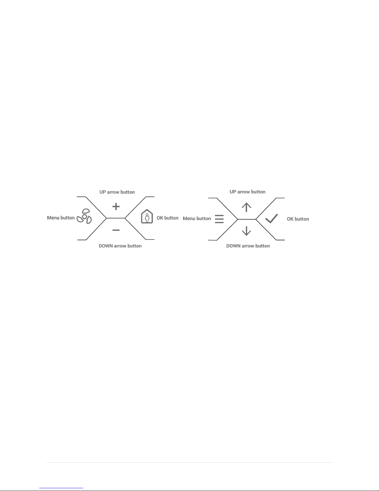
4.9 Key Pad
There are four push buttons mounted in the Panel (see Figure 15 below). All buttons
together create a 4-button Key Pad which can be illuminated to help localize it in dark
places. Key Pad makes it possible for the user to control the Room Panel locally. Control
buttons are dedicated for navigation between different menus as well as for changing,
selecting and displaying the values of particular parameters. All push buttons are located
below LCD display and each of them has different functionality. Functions dedicated for
each button are described in separate sections.
Single pushing of any button enters the Room panel into Active Mode (when the Room
Panel stays in other modes than “Active” and it is powered). When the beeper is active,
single pushing of any button emits the beeper sound.
Figure 15 Left: Standard Key Pad view iSMA-B-LP(-XX), Right: Optional Key Pad view iSMA-B-LP(-XX)-1
4.9.1 Menu button
When the device is in Active mode, single pushing of the button opens the Fan Menu. Menu
button allows to exit particular Menus and parameters’ edit mode. The button cancels
selection of new parameters values (when the parameter stays in edit mode and
FastEditMode is not active).
4.9.2 OK button
When the device is in Active mode, single pushing of the button opens the Occupancy Menu.
When the device is in Menu Edit mode pushing the button opens different Menus and
confirms newly chosen parameters values during edition.
4.9.3 Arrow buttons (up and down)
When the device is in Active mode, pushing the arrow buttons increase/decrease the
setpoint or the offset value.
In Menu Edit Mode arrow buttons switch between submenus and change values of
particular parameters during edition.
Page 29

iSMA-B-LP Room Panel/Modbus
version 1.3 www.gc5.pl Page 28 / 121
4.9.4 Key Pad Background Illumination Settings
When one of four keypad buttons is pressed, the Room Panel changes state into Active
mode. The same situation happens when the power supply is reconnected or after the Room
Panel restart. In case when there is no keypad activity and the Room Panel stays ON, the
subsequent Background illumination modes activate. Key Pad illuminates only when the
value of the register bit DEVICE_CONFIGURATION bit 4 is “true”. If not, Key Pad is never
illuminated.
Particular modes activate sequentially one after another according to the following
sequence:
4. Active – the mode activates after pushing any keypad button or after the Room Panel
restart. Key Pad illuminates with a brightness level stored in
BACKGROUND_ILLUMINATION_KEY_PAD_FOR_ACTIVE_MODE register. In default
setting, the value of Illumination for the active mode is 10%. It means that the LCD
display illuminates with 10% of the maximum possible brightness. The Key Pad stays in
Active mode for as long as it is determined in
BACKGROUND_ILLUMINATION_KEY_PAD_TIME_TO_IDLE register. The register contains
time value in seconds (iBy default 10 sec) and a time countdown starts when Active
mode becomes active. It means in practice that pressing any of the keypad buttons
resets a timer and countdown starts again.
5. Idle – the mode becomes active always after Active mode (Time to Idle is up). The Key
Pad illuminates with a brightness stored in
BACKGROUND_ILLUMINATION_KEY_PAD_FOR_IDLE_MODE register (in default 40%).
The Key Pad stays in Idle mode during the time value stored in
BACKGROUND_ILLUMINATION_KEY_PAD_TIME_TO_STANDBY register (in default 5 sec).
6. Standby – the mode becomes active always after Idle mode (Time to Standby is up). The
Key Pad illuminates with a brightness level stored in
BACKGROUND_ILLUMINATION_KEY_PAD_FOR_STANDBY_MODE register (in default
60%). The Key Pad stays in Standby mode for as long as Active mode is not initiated.
Actual Key Pad display brightness level value is stored in
BACKGROUND_ILUMINATION_KEY_PAD_CURRENT_VALUE register.
Page 30

iSMA-B-LP Room Panel/Modbus
version 1.3 www.gc5.pl Page 29 / 121
5 Sensors Configuration
There are 3 different sensors which can be built-in in the Room Panel (depending on which
Room Panel version is chosen - see Table 3):
• Temperature sensor
• Humidity sensor
• CO
2
sensor
Actual values from all in-built sensors can be displayed in the Main Menu in a specific order
(see section LCD Display).
Actual sensor values are displayed on 8-segment display block in the LCD display, at the
same time.
14-segment display block shows the name of the parameter actual value of which is
displayed on 8-segment display block. Every numeric value is displayed with assigned unit.
Figure 16 Actual temperature sensor value displayed on 8-segment displays block
and the temperature name displayed on 14 -segment displays block
5.1 Temperature Sensor
All Room Panel versions have in-built temperature sensor. Default temperature unit is oC and
it is displayed together with temperature sensor value (if active).
5.1.1 TEMPERATURE_SENSOR_ACTUAL_VALUE (30301)
Register stores actual value from the temperature sensor (including Temperature Sensor
Offset) multiplied by 10. In the Main Menu the temperature sensor value is displayed directly
(without multiplying). Actual register value is calculated according to the equation:
Actual temperature (register value) = (Actual Sensor Temperature +Temperature Sensor
Offset)*10
Page 31

iSMA-B-LP Room Panel/Modbus
version 1.3 www.gc5.pl Page 30 / 121
5.1.2 TEMPERATURE_SENSOR_OFFSET (40304)
The register contains a value which allows for setting correction for temperature sensor’s
actual value indication. The offset value can be positive or negative. The register value is
also multiplied by 10 as in case of Temperature sensor actual value register. The actual
temperature offset value is added to temperature sensor indication. Default value is 0.
5.1.3 TEMPERATURE_FILTER (40307)
Register contains time constant for temperature sensor low pass filter. The value is
expressed in seconds. The default filter value is 60 seconds. Setting value to 0 disables the
filter.
5.1.4 TEMPERATURE_NAME (40310)
There is one 32-bit register which can contain up to 4 characters (ASCII code) which can be
displayed as a text (name) on 14 segment display block, together with the Temperature
Sensor Actual Value register (displayed on 8-segment display block). In case when a
particular character’s value is 0 (NULL), the character is not displayed. Lower case
characters are automatically changed into upper case characters. The default value is
1297110085 which corresponds to the name “TEMP”.
Example:
Task: Display text “ TMP” (empty space in the first position)
Solution: Register contains two bytes. Each of them contains two characters encoded with
ASCII code.
In the example, the lower byte needs to have NULL + “T” character and higher byte “M” + “P”
characters.
Low byte: “NULL” in ASCII = 0
“T” in ASCII code = 54
Final value which needs to be written down to low byte = 84
High byte: “M” in ASCII code = 4D
“P” in ASCII code = 50
Final value which needs to be written down to high byte = 19792
32-bit register has a structure = 0x4D500054
The value which has to be written to register = 1297088596
Page 32

iSMA-B-LP Room Panel/Modbus
version 1.3 www.gc5.pl Page 31 / 121
5.1.5 TEMPERATURE_CONFIGURATION (40316, bit 0 and bit 4)
Bit
Name
0
1
0
Active
Not active
Active(def)
4
ThirdPointActive
No decimal
Decimal(def)
Table 14 Temperature Configuration
Bit 0 of register 40316 is responsible for activation or deactivation of the visibility of
temperature sensor. If bit 0 is active temperature sensor actual value is visible in Main Menu.
Bit 4 of register 40316 is responsible temperature display precision. True value of bit 4
activates temperature displaying precision to the first decimal place. If bit 4 is “false”
temperature is displayed as integer value (without decimal place).
5.2 Humidity Sensor
WARNING! All registers described below are active only when the Room Panel is equipped
with an in-built humidity sensor. Default humidity unit is RH% and is displayed together with
humidity sensor value (if active) permanently (not editable).
5.2.1 HUMIDITY_SENSOR_ACTUAL_VALUE (30302)
The register stores actual value from the humidity sensor (including Humidity Sensor Offset
value) multiplied by 10. In Main Menu the humidity sensor value is displayed directly (without
multiplying).
5.2.2 HUMIDITY_SENSOR_OFFSET (40305)
The register contains a value which allows for setting correction for humidity sensor actual
value indication. The offset value can be positive or negative. The register value is also
multiplied by 10 as in case of Humidity sensor actual value register. The actual humidity
offset value is added to humidity sensor indication. Default value is 0.
5.2.3 HUMIDITY_FILTER (40308)
The register contains time constant for humidity sensor low pass filter, in seconds. The
value is expressed in seconds. The default filter value is 60 seconds. Setting value 0 disables
the filter.
5.2.4 HUMIDITY_NAME (40312)
There is one 32-bit register which can contain up to 4 characters (ASCII code) which can be
Page 33

iSMA-B-LP Room Panel/Modbus
version 1.3 www.gc5.pl Page 32 / 121
displayed as a text (name) on 14 segment display block, together with the
HUMIDITY_SENSOR_ACTUAL_VALUE register (displayed on 8-segment display block). In
case when a particular character value is 0 (NULL), the character is not displayed. Lower
case characters are automatically changed into upper case characters. The default value is
1296648277 which corresponds to the name “HUMI”.
5.2.5 HUMIDITY_CONFIGURATION(Register 40317, bit 0 and bit 4)
Bit
Name
0
1
0
Active
Not active
Active(def)
4
ThirdPointActive
No decimal
Decimal(def)
Table 15 Humidity Configuration
Bit 0 of register 40317 is responsible for activation or deactivation of the visibility of humidity
sensor. If bit 0 is active, actual value of humidity sensor is visible in Main Menu.
Bit 4 of register 40316 is responsible for humidity display precision. True value of bit 4
activates precision of humidity display to the first decimal place. If bit 4 is “false” humidity is
displayed as integer value (without decimal place).
5.3 CO
2
_SENSOR
WARNING! All registers described below are active only when the Room Panel is equipped
with an in-built CO2 sensor.
Default CO2 unit is ppm and it is displayed together with CO2 sensor value (if active)
permanently (not editable). CO2 actual sensor value is displayed in delay of 120 sec after the
Room Panel restart or power supply connection (if bit 0 CO2 Configuration is “true”). The
cause of that is the fact that the CO2 sensor needs up to 2 minutes to warm up from the
moment of power supply connection. The CO2 sensor achieves maximum accuracy after 10
minutes of operation. Worth mentioning is the fact that the in-built CO2 sensor does not need
manual calibration. Calibration algorithm begins after 24 hours of continuous operation,
adjusting the sensor measurement.
5.3.1 CO
2
_SENSOR_ACTUAL_VALUE (30303)
The 30303 register stores actual value from the CO2 sensor (including CO2 Sensor Offset).
5.3.2 CO
2
_SENSOR_OFFSET (40306)
Register contains a value which allows for setting the correction for CO2 sensor actual value
indication. The offset value can be positive or negative. The actual CO2 offset value is added
to CO2 sensor indication. Default offset is 0.
Page 34

iSMA-B-LP Room Panel/Modbus
version 1.3 www.gc5.pl Page 33 / 121
5.3.3 CO
2
_FILTER (40309)
Register contains time constant for CO2 sensor low pass filter, in seconds. The value is
expressed in seconds. The default filter value is 60 seconds. Setting value 0 disables the
filter.
5.3.4 CO
2
_NAME (40314)
There is one 32-bit register which can contain up to 4 characters (ASCII code), which can be
displayed as a text (name) on 14 segment display block together with the
CO2_SENSOR_ACTUAL_VALUE register (displayed on 8-segment display block). In case
when a particular character value is 0 (NULL), the character is not displayed. Lower case
characters are automatically changed into upper case characters. The default value is
838878031 which corresponds to the name “CO2”.
5.3.5 CO
2
_CONFIGURATION (40318, bit 0)
Bit 0 of register 40318 is responsible for activation or deactivation of the visibility of CO2
sensor. If bit 0 is active, CO2 sensor’s actual value is visible in Main Menu. Default value is
“true” (visible, WARNING! CO2 value is visible with delay of 120 sec after the Room Panel
restart or power supply connection).
5.3.6 CO
2
_SETPOINT_FOR_ALARM (40226)
The register contains the Setpoint for alarm value in ppm. If actual CO2 sensor value
increases over the Setpoint value, then the Room Panel indicates CO2 Alarm (for other
indication possibilities see Device Configuration). Default value is 1500 ppm.
5.3.7 CO2_DIFFERENTIAL_FOR_ALARM (40227)
The register contains value in ppm which is the differential for CO2 Alarm value. CO2 Alarm is
activated when CO2 actual sensor value is higher or equal to the sum of
CO2_SETPOINT_FOR_ALARM register value and CO2 differential for Alarm value. CO2 Alarm
is inactive when CO2 actual sensor value is lower or equal to the difference of
CO2_SETPOINT_FOR_ALARM register value and CO2 differential for Alarm value. Default
value is 100 ppm.
CO2 Alarm ON:
CO2 sensor actual value >= CO2 SetpointforAlarm + CO2 differential for Alarm
CO2 Alarm OFF:
CO2 sensor actual value <= CO2 SetpointforAlarm - CO2 differential for Alarm
Page 35

iSMA-B-LP Room Panel/Modbus
version 1.3 www.gc5.pl Page 34 / 121
Figure 17 CO2 Alarm functioning with CO2 differential for Alarm active
6 Setpoint registers
6.1 SETPOINT_VALUE (41501)
The register stores actual Setpoint value multiplied by 10. After device restart, the value is
read from Default Setpoint Value register and set as actual setpoint value. Default value is
210.
6.2 EFFECTIVE_SETPOINT (31502)
The register represents sum of actual Setpoint value and Offset Setpoint value. This value is
a final Setpoint value.
6.3 DEFAULT_SETPOINT (41503)
The register contains default setpoint value. Default Setpoint is set as a Setpoint value after
the Room Panel restart or power supply reconnection (the value of the register Default Value
is written down to Setpoint Value register). Register contains value multiplied by 10. The
default value is 210.
6.4 OFFSET_SETPOINT (41504)
The register contains a value which allows for setting correction for a Setpoint value. The
offset value can be positive or negative. The Offset Setpoint value is added to the Setpoint
value and the result value is entered to the Effective Setpoint register. Register contains
value multiplied by 10. The default value is 0.
Page 36

iSMA-B-LP Room Panel/Modbus
version 1.3 www.gc5.pl Page 35 / 121
6.5 SETPOINT_LOW_LIMIT (41505)
Minimal setpoint value which can be set by user, multiplied by 10. The default value is 180
(18oC).
6.6 SETPOINT_HIGH_LIMIT (41506)
Maximal setpoint value which can be set by user, multiplied by 10. The default value is 240
(24oC).
6.7 OFFSET_RANGE (41507)
Register contains a value which limits OffsetSetpoint value change multiplied by 10. The
value creates a range from – OffsetRange to + OffsetRange of possible Offset values which
can be set by user. The default is 30 (3oC).
Example:
Offset range value is 20. It means that user can change Offset Setpoint value from -2oC to
+2oC.
6.8 SETPOINT_STEP (41508)
The register contains Setpoint STEP value multiplied by 10. When the setpoint is changed by
arrow buttons locally from the Room Panel, single pushing of the arrow button causes
Setpoint change with the STEP value stored in this register. The setpoint can be changed in
the range determined by Setpoint Limits stored in Setpoint Low Limit and Setpoint High
Limit registers.
Setpoint STEP is also automatically adjusted to the Setpoint display precision. When the
register Setpoint Configuration bit 4 is “true”, the Setpoint value is displayed with one
decimal place. In that case Setpoint STEP is also adjusted to one decimal place.
Example:
Setpoint Configuration bit 4 is “true” and SetpointSTEP value equals 5. Actual Setpoint STEP
will be automatically adjusted to one decimal place, so the Setpoint STEP value will be
scaled to 0.5.
The function is active only when Setpoint Configuration bit 4 is “true”. Otherwise the
Setpoint value is displayed as an integer value and SetpointSTEP adjustment is
unnecessary. The default value is 10 (1oC).
6.9 OFFSET_NAME (41509)
There is one 32-bit register which can contain up to 4 characters (ASCII code) which can be
displayed as a text (name) on 14 segment display block together with the Offset Value
Page 37

iSMA-B-LP Room Panel/Modbus
version 1.3 www.gc5.pl Page 36 / 121
register (displayed on 8-segment display block). In case when particular character value is 0
(NULL), the character is not displayed. Lower case characters are automatically changed
into upper case characters. The default value is 1179864902 which corresponds to the
name “OFFS”.
6.10 SETPOINT_NAME (41511)
There is one 32-bit register which can contain up to 4 characters (ASCII code) which can be
displayed as a text (name) on 14 segment display block together with the Setpoint Value
register (displayed on 8-segment display block). In case when particular character value is 0
(NULL), the character is not displayed. Lower case characters are automatically changed
into upper case characters. The default value is 1414550341 which corresponds to the
name “SETP”.
6.11 SETPOINT CONFIGURATION (41513)
6.11.1 SETPOINT_VISIBILITY (Register 41513, bit 0)
Bit 0 is responsible for activation or deactivation setpoint visibility. If bit 0 is active, setpoint
actual value is displayed in Main Menu with the defined display priority (see Main Menu
display). By default bit is “true” (Setpoint visible).
6.11.2 SETPOINT_EDITION (Register 41513, bit 1)
Bit 1 determines possibility to change setpoint locally from the Room Panel. When the bit is
“true” Setpoint is editable and user can change the setpoint value by pushing up/down arrow
buttons. When the bit is “false”, pushing arrow buttons sets the Room Panel in Active Mode
and has no effect on the Setpoint value. By default the bit is “true” (Setpoint editable).
6.11.3 OPERATING_MODE (Register 41513, bit 2)
Bit value determines Setpoint Mode Edition. If the bit is “true”, up and down arrow
pushbuttons change the setpoint value. If the bit is “false”, pushing up/down arrow buttons
changes Setpoint Offset (changes limited to the OffsetRange value). By default the bit is
“true” (Changing Setpoint).
6.11.4 SETPOINT_DISPLAY (Register 41513, bit 3)
Bit 3 function is effective only when bit 2 Operating Mode is “false” (changing offset). Bit 3
allows for choosing which value is displayed during the offset edition.
If the bit is “true”, Effective setpoint value and setpoint name are shown on display during
Offset changing.
If the bit is “false”, LCD display shows OffsetSetpoint value and Offset Name. By default the
bit is “false”.
Page 38

iSMA-B-LP Room Panel/Modbus
version 1.3 www.gc5.pl Page 37 / 121
A) C)
B) D)
Figure 18 Setpoint changing view: A) Setpoint without decimal B) Offset without decimal
C) Setpoint with decimal D) Offset with decimal
6.11.5 THIRD_POINT_ACTIVE (Register 41513, bit 4)
Bit 4 true value activates setpoint display precision to the first decimal place. If bit 4 is
“false”, setpoint is displayed as integer value (without decimal place). The default value is
“true”.
6.11.6 SETPOINT_FAST_EDIT_MODE (Register 41513, Bit 5)
Bit 5 switches between Setpoint Normal Edit and Setpoint Fast Edit modes.
Page 39

iSMA-B-LP Room Panel/Modbus
version 1.3 www.gc5.pl Page 38 / 121
Setpoint Normal Edit mode
When the bit 5 is “false”, Normal Edit mode is active. Setpoint can be changed by the arrow
buttons. The newly chosen Setpoint has to be confirmed by pushing the OK button.
Confirmation of entering the new Setpoint is signalized by double blink of the new Setpoint
and double beeper signal (if enabled, DEVICE_CONFIGURATION bit 0).
When the Setpoint changing is done, the Main Menu is displayed.
Pushing the Menu button before new Setpoint confirmation by the OK Button cancels the
new Setpoint setting procedure and the user returns to the Main Menu.
If the new Setpoint is not confirmed during time value stored in EXIT_EDIT_TIME register, the
new Setpoint setting has failed and the Main Menu is displayed.
Setpoint Fast Edit mode
When the bit 5 is “true”, then Fast Edit mode is active and setting the new Setpoint does not
need a confirmation. The new Setpoint is selected by pushing the OK button. Pushing any
other button confirms the Setpoint choice. The same situation is when time value
EXIT_EDIT_TIME elapsed. The new chosen Setpoint is confirmed. Confirmation of entering
the new Setpoint is signalized by double blink of the new Setpoint name and double beeper
signal (if enabled, DEVICE_CONFIGURATION bit 0).
When Setpoint selection procedure is done, the Main Menu is displayed.
By default the bit is 0 (Normal Edit mode).
6.12 Setting setpoint
Setpoint setting is possible from Main Menu level.
If the Room Panel is in Active Mode or in Idle Mode, pushing the one of arrow buttons leads
to Setpoint Edit mode (if Setpoint is editable, see Setpoint Edition).
6.12.1 Operating Mode is “true” (see Operating Mode)
When Setpoint is in Edit Mode, its value, unit and name flash with frequency calculated
according to the value stored in SUBMENU_ICON_FLASHING_TIME register.
Pushing the up arrow button increases Setpoint value with the STEP stored in
SETPOINT_STEP register (for detailed functioning see SetpointSTEP).
If entered value is higher than the value stored in SETPOINT_HIGH_LIMIT register, the actual
Setpoint value is overwritten by the value in that register.
Pushing the down arrow button decreases Setpoint value with the STEP stored in
SETPOINT_STEP register (for detailed functioning see SetpointSTEP).
If entered value is lower than the value stored in SETPOINT_LOW_LIMIT register, the actual
Setpoint value is overwritten by the value in that register.
Page 40

iSMA-B-LP Room Panel/Modbus
version 1.3 www.gc5.pl Page 39 / 121
6.12.2 Operating Mode is false (see Operating Mode )
In case, when Operating Mode is “false”, the user changes Setpoint indirectly by changing
Offset.
When SETPOINT_CONFIGURATION bit 3 Setpoint Display is “false” then OffsetSetpoint is
displayed.
When Offset is in Edit Mode, its value, unit and name flash with frequency calculated
according to the value stored in SUBMENU_ICON_FLASHING_TIME register.
Pushing the up arrow button increases Offset Setpoint value with the STEP stored in
SETPOINT_STEP register (for detailed functioning see SetpointSTEP).
If entered value is higher than the value stored in OFFSET_RANGE register, the actual
Offset_Setpoint value is overwritten by the value in that register.
Pushing the down arrow button decreases Offset Setpoint value with the STEP stored in
SETPOINT_STEP register (for detailed functioning see SetpointSTEP).
If entered value is lower than the negative value of the OFFSET_RANGE register, the actual
Offset Setpoint value is overwritten by the value in that register.
When SETPOINT_CONFIGURATION bit 3 Setpoint Display is “true”, procedure is analogical,
but instead of displaying Offset Setpoint and Offset Name on LCD display, Effective Setpoint
with Setpoint Name is displayed.
Page 41

iSMA-B-LP Room Panel/Modbus
version 1.3 www.gc5.pl Page 40 / 121
7 Fan Configuration Registers
The Room Panel allows Fan control with actual Fan status indication. There are special
group of icons responsible for fan status indication. Fan Configuration registers allow to
select different fan control modes corresponding to different fan types. According to actual
fan status different icons combinations are displayed. It allows quick preview and service of
the fan status.
The user can switch different fan modes locally in a very simple way. Fan Mode and Manual
Speed Setting are available from Main Menu level. When the Room Panel is in Active Mode
single pushing Menu button enter Fan Submenu Edition. On 14-segment displays’ block text
“FAN” flashes and on 8-segment displays’ block name of FAN_MODE is displayed according
to which Fan Mode is already active (see table Fan Mode Name).
7.1 FAN_CURRENT_SPEED (41601)
The register stores numeric value corresponding to current fan speed. Particular register
value is the base for displaying determined group of icons (see table below). The register
value can be used as an actual fan status indication. This register has software limitation
where the max. value is 6.
Register value
Visualization
0(def)
1 2 3 4 5 6
Table 16 Fan Current Speed states visualization.
7.2 FAN_MODE (41602)
The register contains numeric value which corresponds to FAN_MODE. There are up to 5
different fan modes which can be selected locally from the Fan Edit Submenu level. (see
table 16). To enter Fan Edit Submenu, the Menu button need to be pushed when the Room
Page 42

iSMA-B-LP Room Panel/Modbus
version 1.3 www.gc5.pl Page 41 / 121
Panel is in Active Mode. Particular fan modes availability depends on FAN_TYPE register
value (see table 17). Default texts for particular fan modes can be changed (see Fan Mode
Name). This register has software limitation where the max. value is 4.
Fan Mode text on LCD
Fan Mode register value
OFF 0 I
1(def)
II 2 III 3 AUTO
4
Table 17 Fan mode selection
7.3 FAN_TYPE (41603)
A register contains numeric value corresponding to information about Fan type. Fan type
selection determines which fan modes are available in FAN_MODE register. This register has
software limitation where the max. value is 6. Available fan modes in particular Fan type
selection are shown in the table below:
Register value
Fan type
Comment
Available fan modes’ texts on LCD
0
0-10V(def)
Fan is controlled by
analog value 0-10 VDC
OFF
I
II
III
Auto
1
1- Speed
1-Speed Fan
OFF
I
Auto
2
2- Speed
2-Speed Fan
OFF
I
II
Auto
3
3- Speed
3-Speed Fan
OFF
I
II
III
Auto
4
1- Speed
1 – Speed Fan without AUTO mode
OFF
I
5
2- Speed
2 – Speed Fan without AUTO mode
OFF
I
II
6
3- Speed
3 – Speed Fan without AUTO mode
OFF
I
II
III
Table 18 Fan type register
Page 43

iSMA-B-LP Room Panel/Modbus
version 1.3 www.gc5.pl Page 42 / 121
WARNING!: The register values from 4 to 6 (1-3 Speed Fan without AUTO mode) have to be
set when fan works in Local Mode (see FanLocalMode).
7.4 FAN_MODE_NAME (41604-41612)
For user-friendly use, FAN_MODE register value is displayed on LCD as a text instead of
numeric value. There are six 32-bit registers assigned with six different fan modes, which
can contain up to 4 characters according to the ASCII code (see example in Temperature
Name). The value of 32-bit register is displayed on 8-segment display block as a text. In case
when particular ASCII code value is 0(NULL), the character is not displayed. Lower case
characters are automatically changed into upper case characters.
Register address
Default name
Corresponding Fan mode register value
41604
OFF
0
41606
AUTO
1
41608
I
2
41610
II
3
41612
III
4
Table 19 Fan name registers
7.5 FAN_CONFIGURATION (41614)
7.5.1 FAN_CURRENT_SPEED_VISIBILITY (Register 41614, bit 0)
Bit 0 is responsible for activation or deactivation Fan Current Speed visibility. If bit 0 is active
Fan Current Speed is visible as a group of Icons. The icons indicate fan activity (run status),
actual speed and auto/manual mode.
Figure 19 Fan Icon
The default value is 1(fan current speed is visible).
7.5.2 FAN_EDITION (Register 41614, bit 1)
Bit 1 determines if FAN_MODE is editable locally from the Room Panel. When the bit is “true”
the Fan Edit Submenu is active and the user can set FAN_MODE. When the bit is “false” the
Fan Edit Submenu is inactive. The default value is 1 (FAN_MODE is editable).
7.5.3 PART_EDITABLE (Register 41614, Bit 2)
Bit 2 switches between Fan Full Edition and Fan Part Edition modes.
Run indication
(symbol rotates when a fun is running)
Auto/manual mode indication
(Hand symbol when manual mode is active)
Actual Speed symbol
Page 44

iSMA-B-LP Room Panel/Modbus
version 1.3 www.gc5.pl Page 43 / 121
Fan Full Edition
In Fan Full Edition mode all modes stored in FAN_MODE register are available from Fan Edit
Submenu level.
Fan Part Edition
In Fan Part Edition mode user can switch only between Auto and OFF FAN_MODE from Fan
Edit Submenu level, all other fan modes are unavailable.
Bit 2 value
Function
0
Fan Full Edition(def)
1
Fan Part Edition
Table 20 Part Edit mode
7.5.4 FAN_CONFIG_FAST_EDIT_MODE (Register 41614, Bit 5)
Bit 5 switches between Fan Normal Edit and Fan Fast Edit modes.
Fan Normal Edit mode
When the bit 5 is “false” Normal Edit mode is active. Particular fan modes are selected by
the arrow buttons. The newly chosen FAN_MODE has to be confirmed by pushing the OK
button.
The new FAN_MODE entering confirmation is signalized by double blink of the new
FAN_MODE name and assigned symbol (see Fan Mode selection table) and double beeper
signal (if enabled, DeviceConfiguration bit 0).
When Fan mode selection is done, the Main Menu is displayed.
Pushing the Menu button before new FAN_MODE confirmation by the OK Button cancels the
new FAN_MODE setting procedure and the user is get back to the Main Menu.
If the new FAN_MODE is not confirmed during time value stored in EXIT_EDIT_TIME register
the new FAN_MODE selection is failed and the Main Menu is displayed.
Fan Fast Edit mode
When the bit 5 is “true” then Fast Edit mode is active and setting the new FAN_MODE
doesn’t need a confirmation. The new FAN_MODE is selected by pushing the Menu button.
Pushing any other button confirms the new FAN_MODE choice. The same situation is when
time value EXIT_EDIT_TIME elapsed. The new chosen FAN_MODE is confirmed. The new
FAN_MODE entering confirmation is signalized by double blink of the new FAN_MODE name
and assigned symbol (see FAN_MODE selection table) and double beeper signal (if enabled,
DEVICE_CONFIGURATION bit 0).
When Fan mode selection procedure is done, the Main Menu is displayed.
By default the bit is 0 (Normal Edit mode).
Page 45

iSMA-B-LP Room Panel/Modbus
version 1.3 www.gc5.pl Page 44 / 121
7.5.5 FAN_CONFIG_LOCAL_MODE (Register 41614, Bit 6)
Local Mode
If the bit 6 is “true” the Room Panel fan setting works in a local mode. It means that the
value of the FAN_CURRENT_SPEED register is determined by the value of the FAN_MODE
register and so the value of the FAN_CURRENT_SPEED register cannot be overwritten by the
higher level system.
Fan Mode
register value
Fan Current Speed
register value
Visualization
0
0
1(def)
1 2
2
3
3
Table 21 Overwriting FAN CURRENT SPEED register by FAN_MODE register in Local mode
BMS Mode
If bit 6 is “false”, the Room Panel fan setting works in BMS mode. FAN_MODE register
works separately from FAN_CURRENT_STATUS register.
By default the bit is “false” (BMS mode).
7.6 FAN_ICON_FLASHING_TIME (41615)
A register contains time value in milliseconds which is the base for calculating a frequency
of flashing run indication icons (set rotation speed of Run Indication symbol). This register
has software limitation where the minimum time value is 50 ms. By default 500 ms (Fan run
indication icons changes repeatedly with 2 Hz frequency).
Page 46

iSMA-B-LP Room Panel/Modbus
version 1.3 www.gc5.pl Page 45 / 121
8 Occupancy Registers
Occupancy mode setting is available from Main Menu level. When Room Panel is in Active
Mode, single pushing of the OK button leads the user to Occupancy Edit Submenu. On 14-
segment display block text “OCCM” flashes (with frequency calculated on
SUBMENU_ICON_FLASHING_TIME basis) and on 8-segment display block name of current
OCCUPANCY_MODE is displayed.(see Occupancy Mode Name).
8.1 OCCUPANCY_CURRENT_STATUS (41701)
The register contains numeric value corresponding to actual occupancy status. Particular
register value is the base for displaying determined group of icons (see table below). This
register has software limitation where the maximum value is 3. The register value can be
used as an actual occupancy status indication.
Register
value
Icon
0 1 2
3
Human symbol
blinks
Table 22 Occupancy Current Status
8.2 OCCUPANCY_MODE (41702)
The register contains numeric value corresponding to OCCUPANCY_MODE. There are two
different occupancy modes which can be selected locally from the Occupancy Edit Submenu
level. (see table below). To enter Occupancy Edit Submenu, the OK button needs to be
pushed when the Room Panel is in Active Mode. This register has software limitation where
the maximum value is 1. Default texts for particular occupancy modes can be changed (see
Occupancy Mode Name).
Occupancy Mode
text on LDC
Register value
UNOC
0
OCC
1
Table 23 Occupancy Current Status
Page 47

iSMA-B-LP Room Panel/Modbus
version 1.3 www.gc5.pl Page 46 / 121
8.3 OCCUPANCY_MODE_NAME (41703-41705)
For a more user-friendly use, OCCUPANCY_MODE register value is displayed on LCD as a
text instead of numeric value. There are two 32-bit registers assigned with two different
occupancy modes, which can contain up to 4 characters according to the ASCII code (see
example in Temperature Name). The value of 32-bit register is displayed on 8-segment
display block as a text. In case when particular ASCII code value is 0 (NULL), the character is
not displayed. Lower case characters are automatically changed into upper case characters.
Register address
Default name
Corresponding Occupancy mode
register value
41703
UNOC
0
41705
OCC
1
Table 24 Occupancy Mode Name registers
8.4 OCCUPANCY_CONFIGURATION (41707)
8.4.1 OCCUPANCY_VISIBILITY (Register 41707, bit 0)
Bit 0 of register 41707 is responsible for activation or deactivation Occupancy Current
Status visibility. If bit 0 is active, Occupancy Current Status is visible as a specific group of
Icons’ configuration.
Figure 20 Occupancy Current Status Icons
The default value is 1 (occupancy mode is visible).
8.4.2 OCCUPANCY_MODE_EDITION (Register 41707, bit 1)
Bit 1of register 41707 determines whether OCCUPANCY_MODE is editable locally from the
Room Panel. When the bit is “true”, the Occupancy Edit Submenu is active and the user can
set Occupancy Mode. When the bit is “false”, the Occupancy Edit Submenu is inactive. The
default value is 1 (Occupancy Mode is editable).
8.4.3 EDIT_MODE (Register 41707, Bit 5)
Bit 5 of register 41707 switches between Occupancy Normal Edit and Occupancy Fast Edit
modes.
In unoccupied mode the human symbol
stays outside of the house symbol
In occupied mode the human symbol stays
inside the house symbol (if Forced
occupied mode human symbol blinks
inside the house)
Page 48

iSMA-B-LP Room Panel/Modbus
version 1.3 www.gc5.pl Page 47 / 121
Occupancy Normal Edit mode
When the bit 5 is “false” Normal Edit mode is active. Particular occupancy modes are
selected by arrow buttons. The newly chosen Occupancy mode has to be confirmed by
pushing the OK button.
Confirmatrion of entering the new Occupancy Mode is signalized by double blink of the new
Occupancy Mode name and assigned symbol (see Occupancy Mode) and double beeper
signal (if enabled, DeviceConfiguration bit 0).
When the Occupancy Mode selection is done, the Main Menu is displayed.
Pushing the Menu button prior to new Occupancy Mode confirmation by the OK Button
cancels the new Occupancy Mode setting procedure and the user returns to the Main Menu.
If the new Occupancy Mode is not confirmed during time value stored in EXIT_EDIT_TIME
register, the new Occupancy Mode selection fails and the Main Menu is displayed.
Occupancy Fast Edit mode
When the bit 5 is “true”, then Fast Edit mode is active and setting the new Occupancy Mode
does not need any confirmation. The new Occupancy Mode is selected by pushing the OK
button. Pushing any other button confirms the new Occupancy Mode choice. The same
situation is when time value EXIT_EDIT_TIME elapsed. The new chosen Occupancy Mode is
confirmed. Confirmatrion of entering the new Occupancy Mode is signalized by double blink
of the new Occupancy Mode name and assigned symbol (see Occupancy Mode) and double
beeper signal (if enabled, DeviceConfiguration bit 0).
Once Occupancy Mode selection procedure is done, the Main Menu is displayed.
By default the bit is 0 (Normal Edit mode).
8.4.4 OCCUPIED_CONFIG_LOCAL_MODE (Register 41707, Bit 6)
Bit 6 of register 41707 switches between Local Mode and BMS Mode.
Local Mode
If the bit 6 is “true”, the Room Panel occupancy setting works in a local mode. It means that
the value of the OCCUPANCY_CURRENT_STATUS register is determined by the value of the
OCCUPANCY_MODE register, and the value of the OCCUPANCY_CURRENT_STATUS register
cannot be overwritten by the higher level system.
Page 49

iSMA-B-LP Room Panel/Modbus
version 1.3 www.gc5.pl Page 48 / 121
Occupancy Mode
Register value
Occupancy Current Status
Register value
Visualization
0
0
1
1
Table 25 Overwriting OCCUPANCY CURRENT SPEED register by OCCUPANCY MODE register in Local mode
BMS Mode
If bit 6 is “false”, the Room Panel occupancy setting works in BMS mode.
OCCUPANCY_MODE register works independently from OCCUPANCY_CURRENT_STATUS
register.
By default the bit is “false” (BMS mode).
Page 50

iSMA-B-LP Room Panel/Modbus
version 1.3 www.gc5.pl Page 49 / 121
9 Registers adjustable locally from the Room Panel
Access from the Main Menu level to any settings menu is possible when the Room Panel is
in Active Mode. OK button together with Menu button have to be pushed longer than the
time value stored in ENTER_MENU_TIME register. Access to any settings menu is protected
by password stored in Panel Password register (default password 1000).
Actual settings menu name blinks on 14-segment display block.
Different settings menu can be chosen by pushing up and down arrow buttons.
To enter particular settings menu the OK button should be pushed.
After entering particular settings menu on 14-segment display block, number of parameter
with the lowest number is displayed.
Different available parameters inside the settings menu can be chosen by pushing up or
down arrow buttons.
All parameters are described in more details in particular sections of this User Manual.
9.1 Configuration (CONF)
Configuration menu contains registers responsible for configuration. Main part of all
available registers refers to main communication registers as baud rate, Modbus address,
stop bits, parity bits and protocol selection. From the configuration menu level user can
change the Room Panel password or read information about implemented firmware version.
All available parameters are presented in the table below:
Parameter
number
Modbus
address
Dec
address
Hex
address
Register Name
Access
Description
1.1
40017
16
0x10
BAUD_RATE
Read &
Write
Memory
48 – 1152 (*100kbs)
1.2
40023
22
0x16
ADDRESS
Read &
Write
Memory
Default: 1
1.3
40018
17
0x11
STOP_BITS
Read &
Write
Memory
1 – one stop bit
2 – two stop bits
1.4
40020
19
0x13
PARITY_BITS
Read &
Write
Memory
0 – disabled
1 – ODD
2 - EVEN
1.5
40024
23
0x17
PROTOCOL
Read &
Write
Memory
0 – Modbus RTU
1 – Modbus ASCII
2 – BACnet MS/TP
1.6
40028
27
0x1B
PANEL_PASSWORD
Read &
Write
Memory
Default: 1000
1.7 - - - FIRMWARE_VERSION
Read Only
Software version
Page 51

iSMA-B-LP Room Panel/Modbus
version 1.3 www.gc5.pl Page 50 / 121
9.2 Device (DEV)
Device settings menu contains registers responsible for global settings. Change of any of
particular parameter has influence on different modes and functions implemented in the
Room Panel. Some of the parameters refer to time settings such as Time format Enter Menu
time, Exit Menu Time or Refresh Time. In the Device settings menu user can switch the
beeper off or disable background illumination of LCD Display or Key Pad. All available
parameters are presented in the table below:
Parameter
number
Modbus
address
Dec
address
Hex
address
Register Name
Access
Description
2.1
40205
204
0xCC
DEVICE CONFIGURATION bit 0
BEEPER
Read &
Write
Memory
0-inactive
1-active(def)
2.2
40205
204
0xCC
DEVICE CONFIGURATION bit 1
TIME_FORMAT
Read &
Write
Memory
0-24h(def)
1-12h
2.3
40205
204
0xCC
DEVICE CONFIGURATION bit 2
TEMPERATURE_UNIT
Read &
Write
Memory
Not supported
2.4
40205
204
0xCC
DEVICE CONFIGURATION bit 3
BACKGROUND_ILLUMINATION_LCD_ACTIVE
Read &
Write
Memory
0-inactive
1-active(def)
2.5
40223
222
0xDE
DEVICE CONFIGURATION bit 4
BACKGROUND_ILLUMINATION_KEYPAD_ACTIVE
Read &
Write
Memory
0-inactive(def)
1-active
2.6
40028
27
0x1B
ENTER_MENU_TIME
Read &
Write
Memory
By default 2 sec.
2.7
40224
223
0xDF
EXIT_EDIT_TIME
Read &
Write
Memory
By default 5 sec.
2.8
40225
224
0xE0
EXIT_MENU_TIME
Read &
Write
Memory
By default 10 sec.
2.9
40217
216
0xD8
REFRESH_TIME
Read &
Write
Memory
By default 2 sec.
Page 52

iSMA-B-LP Room Panel/Modbus
version 1.3 www.gc5.pl Page 51 / 121
9.3 Temperature (TEMP)
Temperature Settings menu contains registers referring to temperature sensor display and
temperature control settings. User is able to switch on/off temperature sensor value display,
set temperature sensor filter or change temperature sensor offset. All available parameters
are presented in the table below:
Parameter
number
Modbus
address
Dec
address
Hex
address
Register Name
Access
Description
3.1
40316
315
0x13B
TEMPERATURE_ CONFIGURATION bit 0
ACTIVE
Read &
Write
Memory
0-inactive
1-active(def)
3.2
40316
315
0x13B
TEMPERATURE_CONFIGURATION bit 4
THIRD_POINT_ACTIVE
Read &
Write
Memory
0-inactive
1-active(def)
3.3
40307
306
0x132
TEMPERATURE_FILTER
Read &
Write
Memory
By default 60
sec
3.4
40304
303
0x12F
TEMPERATURE_OFFSET
Read &
Write
Memory
By default 0
9.4 Humidity (HUM)
Humidity Settings menu contains registers referring to humidity sensor display and humidity
control settings. User is able to switch on/off humidity sensor value display, set humidity
sensor filter or change humidity sensor offset. All available parameters are presented in the
table below:
Parameter
number
Modbus
address
Dec
addres
s
Hex
addres
s
Register Name
Access
Description
4.1
40317
316
0x13C
HUMIDITY_CONFIGURATION bit 0
ACTIVE
Read &
Write
Memory
0-inactive
1-active(def)
4.2
40317
316
0x13C
HUMIDITY_CONFIGURATION bit 4
THIRD_POINT_ACTIVE
Read &
Write
Memory
0-inactive
1-active(def)
4.3
40308
307
0x133
HUMIDITY_FILTER
Read &
Write
Memory
By default 60
sec
4.4
40305
304
0x130
HUMIDITY_OFFSET
Read &
Write
Memory
By default 0
Page 53

iSMA-B-LP Room Panel/Modbus
version 1.3 www.gc5.pl Page 52 / 121
9.5 CO2 (CO2)
CO2 Settings menu contains registers referring to CO2 sensor display and CO2 control
settings. User is able to switch on/off CO2 sensor value display, set CO2 sensor filter or
change CO2 sensor offset. All available parameters are presented in the table below:
Paramete
r
number
Modbus
address
Dec
addres
s
Hex
addres
s
Register Name
Access
Description
5.1
40318
317
0x13D
CO2 CONFIGURATION bit 0
ACTIVE
Read &
Write
Memory
0-inactive
1-active(def)
5.2
40309
308
0x134
CO2_FILTER
Read &
Write
Memory
By default 60
sec
5.3
40307
306
0x132
CO2_OFFSET
Read &
Write
Memory
By default 0
5.4
40226
225
0xE1
CO2_SETPOINT
Read &
Write
Memory
By default 1500
ppm
Page 54

iSMA-B-LP Room Panel/Modbus
version 1.3 www.gc5.pl Page 53 / 121
9.6 Setpoint (SETP)
In the Setpoint Settings menu user has access to main setpoint registers. It is possible to
change locally from the Room Panel most useful Setpoint parameters, such as default
setpoint, low and high setpoint limit, setpoint STEP or offset range. User can also decide if
Setpoint value should be displayed in the Main Menu or if Setpoint or offset should be
changed during Setpoint Edition. All available parameters are presented in the table below:
Parameter
number
Modbus
address
Dec
address
Hex
address
Register Name
Access
Description
6.1
41513
1512
0x5E8
SETPOINT_CONFIGURATION bit 0
ACTIVE
Read &
Write
Memory
0-inactive
1-active(def)
6.2
41513
1512
0x5E8
SETPOINT_CONFIGURATION bit 1
EDITABLE
Read &
Write
Memory
0-inactive
1-active(def)
6.3
41513
1512
0x5E8
SETPOINT_CONFIGURATION bit 2
OPPERATING_MODE
Read &
Write
Memory
0-changing offset
1-changing setpoint(def)
6.4
41513
1512
0x5E8
SETPOINT_CONFIGURATION bit 3
SETPOINT_DISPLAY
Read &
Write
Memory
0-changing offset
1-changing effective setpoint(def)
6.5
41513
1512
0x5E8
SETPOINT_CONFIGURATION bit 4
THIRD_POINT_ACTIVE
Read &
Write
Memory
0-inactive
1-active(def)
6.6
41513
1512
0x5E8
SETPOINT_CONFIGURATION bit 5
FAST_EDIT_MODE
Read &
Write
Memory
0-inactive(def)
1-active
6.7
41503
1502
0x5DE
DEFAULT_SETPOINT
Read &
Write
Memory
By default 210
6.8
41505
1504
0x5E0
SETPOINT_LOW_LIMIT
Read &
Write
Memory
By default 180
6.9
41506
1505
0x5E1
SETPOINT_HIGH_LIMIT
Read &
Write
Memory
By default 240
6.10
41507
1506
0x5E2
OFFSET_RANGE
Read &
Write
Memory
By default 30
6.11
41508
1507
0x5E3
SETPOINT_STEP
Read &
Write
Memory
By default 10
Page 55

iSMA-B-LP Room Panel/Modbus
version 1.3 www.gc5.pl Page 54 / 121
9.7 Fan (Fan)
The registers of the Fan Settings Menu refer to Fan Configuration settings. User can change
fan type or decide if Fan Status should be displayed in the Main Menu or not. Parameter
Editable can determine if user can change particular Fan Modes. All available parameters are
presented in the table below:
Paramete
r
number
Modbus
address
Dec
addres
s
Hex
address
Register Name
Access
Description
7.1
41614
1613
0x64D
FAN_CONFIGURATION bit 0
VISABLE_FAN_CURRENT_SPEED
Read &
Write
Memory
0-inactive
1-active(def)
7.2
41614
1613
0x64D
FAN_CONFIGURATION bit 1
EDITABLE
Read &
Write
Memory
0-inactive
1-active(def)
7.3
41614
1613
0x64D
FAN_CONFIGURATION bit 2
PART_EDITABLE
Read &
Write
Memory
0-inactive(def)
1-active
7.4
41614
1613
0x64D
FAN_CONFIGURATION bit 5
FAST_EDIT_MODE
Read &
Write
Memory
0-inactive(def)
1-active
7.5
41615
1614
0x64E
FAN_ICON_FLASHING_TIME
Read &
Write
Memory
By default 500
ms
7.6
41603
1602
0x642
FAN_TYPE
Read &
Write
Memory
0-0-10V(def)
1-1-Speed
2-2-Speed
3-3-Speed
9.8 Occupancy (OCCU)
Occupancy Settings menu contains registers referring to Occupancy Configuration. User can
decide if Current Occupancy Status should be displayed in the Main Menu or not. Parameter
Editable can determine if user can change Occupancy Mode. All available parameters are
presented in the table below:
Parameter
number
Modbus
address
Dec
address
Hex
address
Register Name
Access
Description
8.1
41707
1706
0x6AA
OCCUPANCY_CONFIGURATION bit 0
VISABLE_OCCUPANCY_CURRENT_STATUS
Read &
Write
Memory
0-inactive
1-active(def)
8.2
41707
1706
0x6AA
OCCUPANCY_CONFIGURATION bit 1
EDITABLE
Read &
Write
Memory
0-inactive
1-active(def)
8.3
41707
1706
0x6AA
OCCUPANCY_CONFIGURATION bit 5
FAST_EDIT_MODE
Read &
Write
Memory
0-inactive(def)
1-active
Page 56

iSMA-B-LP Room Panel/Modbus
version 1.3 www.gc5.pl Page 55 / 121
10 Main Menu user defined parameters.
There are 8 numeric and 8 Boolean user-defined parameters available in the Main Menu. All
of them are Read Only type locally for the Room Panel (Read & Write type for the higher level
system) and they are written to EEPROM memory (register values are remembered after the
room Panel restart or power failure).
Each parameter has to be activated to be visible. Active parameters are displayed in the
main menu in a specified sequence (read more in section Refreshing time)
After Room Panel restart user-defined parameters are not displayed until they are
overwritten from a higher level system (Master Controller).
The Main Menu user-defined parameters are implemented for displaying additional
information.
11 Submenus with user defined parameters
The Room Panel is equipped with a special group of registers which allows to define
parameters by the user.
User defined parameters are grouped into 6 submenus.
1. Temperature submenu
2. Fan submenu
3. Light submenu
4. Blind submenu
5. Alarm submenu
6. Occupancy submenu
Each submenu is automatically activated if one of the parameters assigned to that submenu
is active. When the particular submenu is active, then the icon of that submenu is displayed
in the Main Menu (see Submenu Icon Display table). Fan and Occupancy submenu icons are
displayed in different configuration according to actual Fan and Occupancy Status (see
sections about Fan registers and Occupancy registers).
In each submenu there are available 8 numeric and 8 Boolean user-defined parameters.
All user-defined parameters in each submenu are used for displaying and setting different
values locally from the Room Panel. All are written to EEPROM memory (register values are
remembered after the Room Panel restart or power failure).
Access to each submenu can be protected by a password (see Submenu protection).
11.1 Numeric parameter type registers
Each submenu has 8 numeric user-defined parameters. Each of user-defined parameters
has the same structure: contains 7 registers dedicated to different functionalities and
purposes. Each register isdescribed below (Exact Modbus address for each register: see the
list of all Modbus registers).
Page 57

iSMA-B-LP Room Panel/Modbus
version 1.3 www.gc5.pl Page 56 / 121
11.1.1 XPresentValue (X = [1.8])
The register contains actual value of the parameter. The default value is 0.
11.1.2 XName (X = [1.8])
There is one 32-bit register which can contain up to 4 characters (ASCII code) which can be
displayed as a text (name) on 14-segment display block together with the Present Value
register (displayed on 8-segment display block). In case when particular character value is 0
(NULL), the character is not displayed. Lower case characters are automatically changed
into upper case characters. The default name is NUMX where X=[1.8] (ex. Register value for
name “NUM1” = 1295076949).
11.1.3 XPriority (X = [1.8])
The register contains value which determines parameter priority. The parameter priority
determines the sequence of parameters displayed inside the particular submenu. The
parameter with the highest priority is displayed as a first parameter in submenu. The
parameter with the lowest priority is displayed as a last parameter in Submenu. If two or
more parameters have the same priority, the sequence of displaying based on register
addresses (the register with the lowest address is displayed as first). Default priority for all
user-defined parameters is 0.
11.1.4 XSTEP (X = [1.8])
The register contains value which is a STEP during parameter value edition. The default
value is 0.
11.1.5 XLowLimit (X = [1.8])
The register contains minimal value of the parameter (minimal value which can be set locally
from the Room Panel). The default value is 0.
11.1.6 XHIGH_LIMIT (X = [1.8])
The register contains maximal value of the parameter (maximal value which can be set
locally from the Room Panel). The default value is 0.
11.1.7 XConfiguration (X = [1.8])
11.1.7.1 Visibility bit 0
Bit 0 activates parameter visibility. If bit 0 is active, parameter actual value is displayed in the
particular Submenu with the defined display priority. By default bit is 0 (Parameter is
inactive).
Page 58

iSMA-B-LP Room Panel/Modbus
version 1.3 www.gc5.pl Page 57 / 121
11.1.7.2 Editable bit 1
Bit 1 activates edition of the parameter value locally from the Room Panel. When the bit is
“true” parameter is editable and user can change its value. By default the bit is “false” (not
editable).
11.1.7.3 First point Active bit 2
Bit 2 activates parameter display precision to the first decimal place. The default value is
“false”.
11.1.7.4 Second point Active bit 3
Bit 3 activates parameter display precision to the second decimal place. The default value is
“false”.
11.1.7.5 Third point Active bit 4
Bit 4 activates parameter display precision to the third decimal place. The default value is
“false”.
11.1.7.6 oC Unit Active bit 6
If the bit is “ “true”, then together with actual parameter Present Value the oC unit is
displayed. The default value is 0.
11.1.7.7 F Unit Active bit 7
If the bit is “true”, then together with actual parameter Present Value the oF unit is displayed.
The default value is 0.
11.1.7.8 Pa Unit Active bit 8
If the bit is “true”, then together with actual parameter Present Value the Pa unit is displayed.
The default value is 0.
11.1.7.9 Lx Unit Active bit 9
If the bit is “true”, then together with actual parameter Present Value the Lx unit is displayed.
The default value is 0.
11.1.7.10 ppm Unit Active bit 10
If the bit is “true”, then together with actual parameter Present Value the ppm unit is
displayed. The default value is 0.
Page 59

iSMA-B-LP Room Panel/Modbus
version 1.3 www.gc5.pl Page 58 / 121
11.1.7.11 m3h Unit Active bit 11
If the bit is “true”, then together with actual parameter Present Value the m3h unit is
displayed. The default value is 0.
11.1.7.12 %Rh Unit Active bit 12
If the bit is “true”, then together with actual parameter Present Value the %Rh unit is
displayed. The default value is 0.
11.1.7.13 Ls Unit Active bit 13
If the bit is “true”, then together with actual parameter Present Value the l/s unit is displayed.
The default value is 0.
11.1.7.14 % Unit Active bit 14
If the bit is “true”, then together with actual parameter Present Value the % unit is displayed.
The default value is 0.
11.1.7.15 h Unit Active bit 15
If the bit is “true”, then together with actual parameter Present Value the h unit is displayed.
The default value is 0.
11.2 Boolean parameter type registers
Each submenu has 8 Boolean user-defined parameters. Each of user-defined parameters
has the same structure: it contains 6 registers dedicated to different functionalities and
purposes. Each register is described below (Exact Modbus address for each register: see the
list of all Modbus registers).
11.2.1 XPresentValue (X = [1.8])
The register contains actual value of the parameter. The default value is 0 (inactive).
Note: Please note that the register is an integer type. To use Boolean type point refer to
Submenu Boolean All present value registers.
11.2.2 XName (X = [1.8])
There is one 32-bit register, which can contain up to 4 characters (ASCII code) which can be
displayed as a text (name) on 14-segment display block together with the Present Value
register (displayed on 8-segment display block). In case when particular character value is 0
(NULL), the character is not displayed. Lower case characters are automatically changed
into upper case characters. The default name is BOOX where X=[1.8] (ex. Register value for
name “BOO1” = 1328628303).
Page 60

iSMA-B-LP Room Panel/Modbus
version 1.3 www.gc5.pl Page 59 / 121
11.2.3 XTrueText (X = [1.8])
To user-friendly use, Present Value register value is displayed on LCD as a text instead of
numeric value. There is one 32-bit register assigned with Active state of the Present Value
register, which can contain up to 4 characters according to the ASCII code (see example in
Temperature Name). The value of 32-bit register is displayed on 8-segment display block as
a text. In case when particular ASCII code value is 0 (NULL), the character is not displayed.
Lower case characters are automatically changed into upper case characters (ex. Register
value for name “ON” = 20302).
11.2.4 XFalseText (X = [1.8])
For a more user-friendly use, Present Value register value is displayed on LCD as a text
instead of numeric value. There is one 32-bit register assigned with Inactive state of the
Present Value register, which can contain up to 4 characters according to the ASCII code
(see example in Temperature Name). The value of 32-bit register is displayed on 8-segment
display block as a text. In case when particular ASCII code value is 0 (NULL), the character is
not displayed. Lower case characters are automatically changed into upper case characters.
The default name is “OFF” (register value=1174425414).
11.2.5 XPriority (X = [1.8])
The register contains value which determines parameter priority. Parameter priority
determines the sequence of parameters display inside the particular submenu. The
parameter with the highest priority is displayed as first parameter in submenu. The
parameter with the lowest priority is displayed as last parameter in Submenu. If two or more
parameters have the same priority, the sequence of displaying is based on register
addresses (the register with the lowest address is displayed first). Default priority for all userdefined parameters is 0.
11.2.6 XConfiguration (X = [1.8])
11.2.6.1 Visibility bit 0
Bit 0 activates parameter visibility. If bit 0 is active, actual value of a parameter is displayed
in the particular Submenu with the defined displaying priority. By default bit is 0 (Parameter
inactive).
11.2.6.2 Editable bit 1
Bit 1 activates possibility of changing parameter value locally from the Room Panel. When
the bit is “true”, the parameter is editable and user can change its value. By default bit is
“false” (not editable).
Page 61

iSMA-B-LP Room Panel/Modbus
version 1.3 www.gc5.pl Page 60 / 121
11.3 Submenu MenuActivePoints registers
For each Submenu there is a special register which indicates if there is any active
parameters inside the particular submenu. If the value of Menu Active Points register is
higher than 0, it means that there is at least one active parameter in Submenu and icon
assigned to that submenu is displayed.
Menu Active Points register reads values from all XConfiguration Active bits inside a
particular Submenu. If one of Active bit is “true”, Register Submenu Active points becomes
positive.
11.4 Submenu Boolean All Present Value registers (40107 - 40113)
For each submenu there is a special register which contains all Boolean present values
inside a particular submenu.
Setting true value for single bit sets true value for assigned Boolean Point according to the
Table below. By default all bits of the register are “false”.
Bit
Name
0
1
0
Boolean1PresentValue
Not active(def)
Active
1
Boolean2PresentValue
Not active(def)
Active
… … … … … … … … 6
Boolean7PresentValue
Not active(def)
Active
7
Boolean8PresentValue
Not active(def)
Active
Page 62

iSMA-B-LP Room Panel/Modbus
version 1.3 www.gc5.pl Page 61 / 121
12 List of all Modbus Registers
The table below shows all registers available for the Room Panel.
Modbus
Address
Dec
Address
Hex
Address
Register Name
Access
Description
40001
0
0x00
VERSION_TYPE
Read & Write
First byte means version and another one type of a
device. Allows to enable 1 of 4 device actions.
30004
3
0x03
RECEIVED__FRAMES
COUNTER (32–bits)
Read Only
Default state is 0. Reset at the unit start and change
of transmission parameters.
30006
5
0x05
ERROR_FRAMES
COUNTER (32–bits)
Read Only
Default state is 0. Reset at the unit start and change
of transmission parameters.
30008
7
0x07
TRANSMITTED_FRAME
COUNTER _(32–bits)
Read Only
Default state is 0. Reset at the unit start and change
of transmission parameters.
30012
12
0x0C
LIVE_TIME
(32–bits)
Read Only
Up device time in sec
40015
14
0x0E
BACNET_DEVICE_ID
(32–bits)
Read & Write
Memory
Default 0xFFFFFFFF
40017
16
0x10
BAUD_RATE
Read & Write
Memory
Transmission speed is defined by the user,
calculation using the formula:
The default value is 11520 (115200 bps)
40018
17
0x11
STOP_BITS
Read & Write
Memory
Supported values are 1 and 2
The default value 1
40020
19
0x13
PARITY_BIT
Read & Write
Memory
The default value is 0 (no parity)
Allowed values:
Value
Description
0 (default)
none 1 Odd 2 Even
40021
20
0x14
REPLAY_DELAY
Read & Write
Memory
Delay in ms before sending response
The default value is 0.
40023
22
0x16
ADDRESS
Read & Write
Memory
Modbus address of the device.
The default value is 1.
40024
23
0x17
PROTOCOL
Read & Write
Memory
0 – Modbus RTU (default)
1 – Modbus ASCII
2 – BACnet MS/TP
40028
27
0x1B
PANEL_PASSWORD
Read & Write
Memory
Password for Menu Edit Mode. Default is 1000.
30029
28
0x1C
SENSORS
Read Only
BIT0 – humidity sensor
BIT1 – CO2 sensor
BIT2 – NTC sensor
30201
200
0xC8
BACKGROUND_ILLUMINATION
LCD_CURRENT_VALUE
Read Only
Actual display illumination value
30202
201
0xC9
BACKGROUND_ILLUMINATION
Read Only
Actual Key Pad illumination value
Page 63

iSMA-B-LP Room Panel/Modbus
version 1.3 www.gc5.pl Page 62 / 121
Modbus
Address
Dec
Address
Hex
Address
Register Name
Access
Description
KEY_PAD_CURRENT_VALUE
40203
202
0xCA
HOURS
Read & Write
Hours part in time display
40204
203
0xCB
MINUTES
Read & Write
Minutes part in time display
40205
204
0xCC
DEVICE_CONFIGURATION
Read & Write
Memory
Bit
Name
0
1
0
Beeper
Not active
Active(def) 1 Format
24h(def)
12h
3
Illumination
LCD
Not active
Active(def) 4 Illumination
Key Pad
Not
active(def)
Active 5 CO2Alarm
LCD
Not active
Active 6 CO2Alarm
Buzzer
Not active
Active 7 CO2Alarm
HIGH
Not active
Active
10
SubmenuIconDisplayOFF
Not active
Active
11
Panel OFF
Panel
ON(def)
Panel OFF
12
Key Pad OFF
Key Pad
ON(def)
Key Pad
OFF
13
Flashing LCD
Not
active(def)
Active
14
Flashing Key Pad
Not
active(def)
Active
40207
206
0xCE
BACKGROUND_ILLUMINATION
LCD_FOR_ACTIVE_MODE
Read & Write
Memory
Default 60%
40208
207
0xCF
BACKGROUND_ILLUMINATION
LCD_FOR_IDLE_MODE
Read & Write
Memory
Default 40%
40209
208
0xD0
BACKGROUND_ILLUMINATION
LCD_FOR_STANDBY_MODE
Read & Write
Memory
Default 0%
40210
209
0xD1
BACKGROUND_ILLUMINATION
LCD_TIME_TO_IDLE
Read & Write
Memory
Default 10 sec
40211
210
0xD2
BACKGROUND_ILLUMINATION
LCD_TIME_TO_STANDBY
Read & Write
Memory
Default 5 sec
40212
211
0xD3
BACKGROUND_ILLUMINATION
KEY_PAD_ACTIVE_MODE
Read & Write
Memory
Default 10%
40213
212
0xD4
BACKGROUND_ILLUMINATION
KEY_PAD_IDLE_MODE
Read & Write
Memory
Default 40%
40214
213
0xD5
BACKGROUND_ILLUMINATION
KEY_PAD_STANDBY_MODE
Read & Write
Memory
Default 60%
40215
214
0xD6
BACKGROUND_ILLUMINATION_KEY
Read & Write
Default 10 sec
Page 64

iSMA-B-LP Room Panel/Modbus
version 1.3 www.gc5.pl Page 63 / 121
Modbus
Address
Dec
Address
Hex
Address
Register Name
Access
Description
PAD_TIME_TO_IDLE
Memory
40216
215
0xD7
BACKGROUND_ILLUMINATION
KEY_PAD_TIME_TO_STANDBY
Read & Write
Memory
Default 5 sec
40217
216
0xD8
REFRESH_TIME
Read & Write
Memory
Default 2 sec
40218
217
0xD9
TIME_CONFIGURATION
Read & Write
Memory
Bit 0 = 1 clock is visible (default)
Bit 0 = 0 clock is not visible
40219
218
0xDA
LCD_ICON_DISPLAY
Read & Write
Memory
Each bit of the register shows or hides assigned Icon
as in the table below:
Bit
Icon Name
Icon
0
Sun
1
Moon
2
Heating
3
Cooling
4
Humidfire
5
Dehumidfire
6
Wireless
7
Settings
8
Eco
9
Recirculation
10
PC
40220
219
0xDB
LCD_ICON_DISPLAY
Read & Write
Memory
Each bit of the register starts flashing of the
assigned Icon.
See table in LCD ICON DISPLAY register description.
40221
220
0xDC
LCD_ICON_FLASHING_TIME
Read & Write
Memory
Time which is the base for calculating frequency of
Icon flashing. Icons are visible for 100% of the time
value stored in the register and hidden for 20% of
Page 65

iSMA-B-LP Room Panel/Modbus
version 1.3 www.gc5.pl Page 64 / 121
Modbus
Address
Dec
Address
Hex
Address
Register Name
Access
Description
that time. Default time: 500ms.
40222
221
0xDD
SUBMENU_ICON_FLASHING_TIME
Read & Write
Memory
Time which is the base for calculating frequency of
Icon flashing. Icons are visible for 100% of the time
value stored in the register and hidden for 20% of
that time. Default time 1000ms.
40223
222
0xDE
ENTER_MENU_TIME
Read & Write
Memory
By default 2 sec.
40224
223
0xDF
EXIT_EDIT_TIME
Read & Write
Memory
By default 5 sec.
40225
224
0xE0
EXIT_MENU_TIME
Read & Write
Memory
By default 10 sec.
40226
225
0xE1
CO2_SETPOINT_FOR_ALARM
Read & Write
Memory
CO2 Alarm setpoint. By default 1500 ppm.
40227
226
0xE2
CO2_HYSTERESIS_FOR_ALARM
Read & Write
Memory
CO2 Alarm hysteresis. By default 100 ppm.
30230
229
0xE5
ALARM_STATUS
Read Only
CO2 Current alarm Status
30301
300
0x12C
TEMPERATURE_SENSOR
Read Only
Actual temperature sensor value with offset.
30302
301
0x12D
HUMIDITY_SENSOR
Read Only
Actual humidity sensor value with offset.
30303
302
0x12E
CO2_SENSOR
Read Only
Actual CO2 sensor value with offset.
40304
303
0x12F
TEMPERATURE_SENSOR_OFFSET
Read & Write
Memory
Temperature sensor offset. Default is 0.
40305
304
0x130
HUMIDITY_SENSOR_OFFSET
Read & Write
Memory
Humidity sensor offset. Default is 0.
40306
305
0x131
CO2_SENSOR_OFFSET
Read & Write
Memory
CO2 sensor offset. Default is 0.
40307
306
0x132
TEMPERATURE_FILTER
Read & Write
Memory
By default 60 sec
40308
307
0x133
HUMIDITY_FILTER
Read & Write
Memory
By default 60 sec
40309
308
0x134
CO2_FILTER
Read & Write
Memory
By default 60 sec
40310
309
0x135
TEMPERATURE_NAME
(32–bits)
Read & Write
Memory
Displayed temperature sensor name. : TEMP
40312
311
0x137
HUMIDITY_NAME
(32–bits)
Read & Write
Memory
Displayed humidity sensor name. : HUMI
40314
313
0x139
CO2_NAME
(32–bits)
Read & Write
Memory
Displayed CO2 sensor name. : CO2
Page 66

iSMA-B-LP Room Panel/Modbus
version 1.3 www.gc5.pl Page 65 / 121
Modbus
Address
Dec
Address
Hex
Address
Register Name
Access
Description
40316
315
0x13B
TEMPERATURE_CONFIGURATION
Read & Write
Memory
Bit
Name
0
1
0
Active
Not active
Active(def)
4
ThirdPointActive
No decimal
Decimal(def)
40317
316
0x13C
HUMIDITY_CONFIGURATION
Read & Write
Memory
Bit
Name
0
1
0
Active
Not active
Active(def)
4
ThirdPointActive
No decimal
Decimal(def)
40318
317
0x13D
CO2_CONFIGURATION
Read & Write
Memory
Bit
Name
0
1
0
Active
Not active
Active(def)
41501
1500
0x5DC
SETPOINT_VALUE
Read & Write
Actual Setpoint Value. After reset default value is
set as Setpoint value.
41502
1501
0x5DD
EFFECTIVE_SETPOINT
Read Only
Sum of Effective Setpoint and Offset value.
41503
1502
0x5DE
DEFAULT_SETPOINT
Read & Write
Memory
By default 21oC
41504
1503
0x5DF
OFFSET_SETPOINT
Read & Write
Memory
By default 0oC
41505
1504
0x5E0
SETPOINT_LOW_LIMIT
Read & Write
Memory
Min available setpoint value. By default 18oC.
41506
1505
0x5E1
SETPOINT_HIGH_LIMIT
Read & Write
Memory
Max available setpoint value. By default 24oC.
41507
1506
0x5E2
OFFSET_RANGE
Read & Write
Memory
Limit offset value. By default 3oC.
41508
1507
0x5E3
SETPOINT_STEP
Read & Write
Memory
Setpoint value STEP. By default 1oC.
41509
1508
0x5E4
OFFSET_NAME
(32–bits)
Read & Write
Memory
Displayed offset name. : OFFS
41511
1510
0x5E6
SETPOINT_NAME
(32–bits)
Read & Write
Memory
Displayed setpoint name. : SETP
Page 67

iSMA-B-LP Room Panel/Modbus
version 1.3 www.gc5.pl Page 66 / 121
Modbus
Address
Dec
Address
Hex
Address
Register Name
Access
Description
41513
1512
0x5E8
SETPOINT_CONFIGURATION
Read & Write
Memory
Bit
Name 0 1
0
Visible
Not visible
Visible(def)
1
Editable
Not Editable
Editable(def)
2
Opperating
Mode
Changing
Offset
Changing
Setpoint(def)
3
Setpoint Display
Show/change
Offset
Show/change
EffectiveSetpoint
4
ThirdPointActive
Not active
Active(def)
5
FastEditMode
Not
active(def)
Active
41601
1600
0x640
FAN_MODE
Read & Write
Register
value
Fan Mode
Visualization
0
OFF
1
Manual Speed 1
(def)
2
Manual Speed 2
3
Manual Speed 3
4
AUTO
41602
1601
0x641
FAN_CURRENT_SPEED
Read & Write
Register
value
Fan Mode
Comment
0
OFF(def)
Fan is OFF
1
Manual Speed
1
Fan works in Speed 1
manual mode
2
Manual Speed
2
Fan works in Speed 2
manual mode
3
Manual Speed
3
Fan works in Speed 3
manual mode
4
Auto Speed 1
Fan works in Speed 1
auto mode
5
Auto Speed 2
Fan works in Speed 2
auto mode
6
Auto Speed 3
Fan works in Speed 3
Page 68

iSMA-B-LP Room Panel/Modbus
version 1.3 www.gc5.pl Page 67 / 121
Modbus
Address
Dec
Address
Hex
Address
Register Name
Access
Description
auto mode
41603
1602
0x642
FAN_TYPE
Read & Write
Memory
Register
value
Fan type
Comment
0
0-10V(def)
Fan is controlled by
analog value 0-10 VDC
1
1- Speed
1-Speed Fan
2
2- Speed
2-Speed Fan
3
3- Speed
3-Speed Fan
41604
1603
0x643
FAN_MODE_0
NAME (32–bits)
Read & Write
Memory
Name for FAN MODE = 0. Default = OFF
41606
1605
0x645
FAN_MODE_1
NAME (32–bits)
Read & Write
Memory
Name for FAN MODE = 1. Default = AUTO
41608
1607
0x647
FAN_MODE_2
NAME (32–bits)
Read & Write
Memory
Name for FAN MODE = 2. Default = _ _ _1
41610
1609
0x649
FAN_MODE_3
NAME (32–bits)
Read & Write
Memory
Name for FAN MODE = 3. Default = _ _11
41612
1611
0x64B
FAN_MODE_4
NAME (32–bits)
Read & Write
Memory
Name for FAN MODE = 4. Default = _111
41614
1613
0x64D
FAN_CONFIGURATION
Read & Write
Memory
Bit
Name 0 1
0
Visible
Not visible
Visible(def)
1
Editable
Not Editable
Editable(def)
2
Part Editable
Fully
edtitable(def)
Auto_Off_Mode
5
FastEditMode
Not
active(def)
Active
41615
1614
0x64E
FAN_ICON_FLASHING_TIME
Read & Write
Memory
Time base for calculating the frequency of the Fan
Icon rotation simulation. By default 500 ms.
41701
1700
0x6A4
OCCUPANCY_MODE
Read & Write
Memory
Occupancy mode setting from the Room panel:
0 – unoccupied
1 - occupied
41702
1701
0x6A5
OCCUPANCY_CURRENT_STATUS
Read & Write
Occupancy mode setting remotely:
Register
value
Occupancy
Mode
0
Unoccupied
1
Occupied
2
Standby
3
Forced occupied
41703
1702
0x6A6
OCCUPANCY_MODE_0
Read & Write
Name for OCCUPANCY MODE = 0. Default = UNOC
Page 69

iSMA-B-LP Room Panel/Modbus
version 1.3 www.gc5.pl Page 68 / 121
Modbus
Address
Dec
Address
Hex
Address
Register Name
Access
Description
NAME (32–bits)
Memory
41705
1704
0x6A8
OCCUPANCY_MODE_1
NAME (32–bits)
Read & Write
Memory
Name for OCCUPANCY MODE = 1. Default = OCC
41707
1706
0x6AA
OCCUPANCY_CONFIGURATION
Read &
WriteMemory
Bit
Name 0 1
0
Visible
Not visible
Visible(def)
1
Editable
Not Editable
Editable(def)
5
FastEditMode
Not
active(def)
Active
12.1.1 List of User defined parameters Modbus registers
12.1.2 Main Menu user defined parameters
Modbus
Address
Dec
Address
Hex
Address
Register Name
Access
Description
40051
50
0x32
MAIN_MENU_NUMERIC1
PRESENTVALUE
Read &
Write
Memory
Present value of the parameter
40320
319
0x13F
MAIN_MENU_NUMERIC1
NAME (32–bits)
Read &
Write
Memory
User-defined parameter name displayed.
40322
321
0x141
MAIN_MENU_NUMERIC1
PRIORITY
Read &
Write
Memory
Priority of the parameter for sequence of displaying
in Main Menu
40323
322
0x142
MAIN_MENU_NUMERIC1
CONFIGURATION
Read &
Write
Memory
Bit
Name
0
1
0
Active
Not active(def)
Active(def)
2
FirstPointActive
Not
decimal(def)
Decimal(def)
3
SecondPointActive
Not
decimal(def)
Decimal(def)
4
ThirdPointActive
Not
decimal(def)
Decimal(def)
6
C unit active
not_visible(def)
visible
7
F unit active
not_visible(def)
visible
8
Pa unit active
not_visible(def)
visible
9
Lx unit active
not_visible(def)
visible
10
ppm unit active
not_visible(def)
visible
11
m3/h unit active
not_visible(def)
visible
12
%Rh unit active
not_visible(def)
visible
13
l/s unit active
not_visible(def)
visible
Page 70

iSMA-B-LP Room Panel/Modbus
version 1.3 www.gc5.pl Page 69 / 121
Modbus
Address
Dec
Address
Hex
Address
Register Name
Access
Description
14
% unit active
not_visible(def)
visible
15
h unit active
not_visible(def)
visible
40052
51
0x33
MAIN_MENU_NUMERIC2
PRESENTVALUE
Read &
Write
Memory
Present value of the parameter
40325
324
0x144
MAIN_MENU_NUMERIC2
NAME (32–bits)
Read &
Write
Memory
Displaying user-defined parameter name.
40327
326
0x146
MAIN_MENU_NUMERIC2
PRIORITY
Read &
Write
Memory
Priority of the parameter for sequence of display in
Main Menu
40328
327
0x147
MAIN_MENU_NUMERIC2
CONFIGURATION
Read &
Write
Memory
See the table in
MAIN_MENU_NUMERIC1Configuration(30323)
40053
52
0x34
MAIN_MENU_NUMERIC3
PRESENTVALUE
Read &
Write
Memory
Parameter Present Value
40340
329
0x149
MAIN_MENU_NUMERIC3
NAME (32–bits)
Read &
Write
Memory
Displaying user-defined parameter name.
40332
331
0x14B
MAIN_MENU_NUMERIC3
PRIORITY
Read &
Write
Memory
Priority of the parameter for sequence of display in
Main Menu
40333
332
0x14C
MAIN_MENU_NUMERIC3
CONFIGURATION
Read &
Write
Memory
See the table in
MAIN_MENU_NUMERIC1Configuration(30323)
40054
53
0x35
MAIN_MENU_NUMERIC4
PRESENTVALUE
Read &
Write
Memory
Present value of the parameter
40335
334
0x14E
MAIN_MENU_NUMERIC4
NAME (32–bits)
Read &
Write
Memory
Displaying user-defined parameter name.
40337
336
0x150
MAIN_MENU_NUMERIC4
PRIORITY
Read &
Write
Memory
Priority of the parameter for sequence of display in
Main Menu
40338
337
0x151
MAIN_MENU_NUMERIC4
CONFIGURATION
Read &
Write
Memory
See the table in
MAIN_MENU_NUMERIC1Configuration(30323)
40055
54
0x36
MAIN_MENU_NUMERIC5
PRESENTVALUE
Read &
Write
Memory
Present value of the parameter
40340
339
0x153
MAIN_MENU_NUMERIC5
NAME (32–bits)
Read &
Write
Memory
Displayed user-defined parameter name.
40342
341
0x155
MAIN_MENU_NUMERIC5
PRIORITY
Read &
Write
Priority of the parameter for sequence of display in
Main Menu
Page 71

iSMA-B-LP Room Panel/Modbus
version 1.3 www.gc5.pl Page 70 / 121
Modbus
Address
Dec
Address
Hex
Address
Register Name
Access
Description
Memory
40343
342
0x156
MAIN_MENU_NUMERIC5
CONFIGURATION
Read &
Write
Memory
See the table in
MAIN_MENU_NUMERIC1Configuration(30323)
40056
55
0x37
MAIN_MENU_NUMERIC6
PRESENTVALUE
Read &
Write
Memory
Present value of the parameter
40345
344
0x158
MAIN_MENU_NUMERIC6
NAME (32–bits)
Read &
Write
Memory
Displaying user-defined parameter name.
40347
346
0x15A
MAIN_MENU_NUMERIC6
PRIORITY
Read &
Write
Memory
Priority of the parameter for sequence of display in
Main Menu
40348
347
0x15B
MAIN_MENU_NUMERIC6
CONFIGURATION
Read &
Write
Memory
See the table in
MAIN_MENU_NUMERIC1Configuration(30323)
40350
349
0x15D
MAIN_MENU_NUMERIC7
NAME (32–bits)
Read &
Write
Memory
Displaying user-defined parameter name.
40057
56
0x38
MAIN_MENU_NUMERIC7
PRESENTVALUE
Read &
Write
Memory
Present value of the parameter
40352
351
0x15E
MAIN_MENU_NUMERIC7
PRIORITY
Read &
Write
Memory
Priority of the parameter for sequence of display in
Main Menu
40353
352
0x15F
MAIN_MENU_NUMERIC7
CONFIGURATION
Read &
Write
Memory
See the table in
MAIN_MENU_NUMERIC1Configuration(30323)
40058
57
0x39
MAIN_MENU_NUMERIC8
PRESENTVALUE
Read &
Write
Memory
Present value of the parameter
40355
354
0x162
MAIN_MENU_NUMERIC8
NAME (32–bits)
Read &
Write
Memory
Displaying user-defined parameter name.
40357
356
0x164
MAIN_MENU_NUMERIC8
PRIORITY
Read &
Write
Memory
Priority of the parameter for sequence of display in
Main Menu
40358
357
0x165
MAIN_MENU_NUMERIC8
CONFIGURATION
Read &
Write
Memory
See the table in
MAIN_MENU_NUMERIC1Configuration(30323)
40107
106
0x6A
MAIN_MENU_BOOLEAN
ALLPRESENTVALUES
Read &
Write
Memory
Bit
Name
0
1
0
Boolean1PresentValue
Not active(def)
Active
1
Boolean2PresentValue
Not active(def)
Active … …
…
… 6 Boolean7PresentValue
Not active(def)
Active
Page 72

iSMA-B-LP Room Panel/Modbus
version 1.3 www.gc5.pl Page 71 / 121
Modbus
Address
Dec
Address
Hex
Address
Register Name
Access
Description
7
Boolean8PresentValue
Not active(def)
Active
40114
113
0x71
MAIN_MENU_BOOLEAN1
PRESENTVALUE
Read &
Write
Memory
Present value of the parameter
40360
359
0x167
MAIN_MENU_BOOLEAN1
NAME (32–bits)
Read &
Write
Memory
Displaying user-defined parameter name.
40362
361
0x169
MAIN_MENU_BOOLEAN1
TRUETEXT (32–bits)
Read &
Write
Memory
Text for parameter “true” state value.
40364
363
0x16B
MAIN_MENU_BOOLEAN1
FALSETEXT (32–bits)
Read &
Write
Memory
Text for parameter “false” state value.
40366
365
0x16D
MAIN_MENU_BOOLEAN1
PRIORITY
Read &
Write
Memory
Priority of the parameter for sequence of display in
Main Menu
40367
366
0x16E
MAIN_MENU_BOOLEAN1
CONFIGURATION
Read &
Write
Memory
Bit
Name
0
1
0
Active
Not active(def)
Active
40115
114
0x72
MAIN_MENU_BOOLEAN2
PRESENTVALUE
Read &
Write
Memory
Present value of the parameter
40369
368
0x170
MAIN_MENU_BOOLEAN2
NAME (32–bits)
Read &
Write
Memory
Displaying user-defined parameter name.
40371
370
0x172
MAIN_MENU_BOOLEAN2
TRUETEXT (32–bits)
Read &
Write
Memory
Text for parameter “true” state value.
40373
372
0x174
MAIN_MENU_BOOLEAN2
FALSETEXT (32–bits)
Read &
Write
Memory
Text for parameter “false” state value.
40375
374
0x176
MAIN_MENU_BOOLEAN2
PRIORITY
Read &
Write
Memory
Priority of the parameter for sequence of display in
Main Menu
40376
375
0x177
MAIN_MENU_BOOLEAN2
CONFIGURATION
Read &
Write
Memory
Bit
Name
0
1
0
Active
Not active(def)
Active
40116
115
0x73
MAIN_MENU_BOOLEAN3
PRESENTVALUE
Read &
Write
Memory
Present value of the parameter
40378
377
0x179
MAIN_MENU_BOOLEAN3
NAME (32–bits)
Read &
Write
Memory
Displaying user-defined parameter name.
40380
379
0x17B
MAIN_MENU_BOOLEAN3
TRUETEXT (32–bits)
Read &
Write
Text for parameter “true” state value.
Page 73

iSMA-B-LP Room Panel/Modbus
version 1.3 www.gc5.pl Page 72 / 121
Modbus
Address
Dec
Address
Hex
Address
Register Name
Access
Description
Memory
40382
381
0x17D
MAIN_MENU_BOOLEAN3
FALSETEXT (32–bits)
Read &
Write
Memory
Text for parameter “false” state value.
40384
383
0x17F
MAIN_MENU_BOOLEAN3
PRIORITY
Read &
Write
Memory
Priority of the parameter for sequence of display in
Main Menu
40385
384
0x180
MAIN_MENU_BOOLEAN3
CONFIGURATION
Read &
Write
Memory
Bit
Name
0
1
0
Active
Not active(def)
Active
40117
116
0x74
MAIN_MENU_BOOLEAN4
PRESENTVALUE
Read &
Write
Memory
Present value of the parameter
40387
386
0x182
MAIN_MENU_BOOLEAN4
NAME (32–bits)
Read &
Write
Memory
Displaying user-defined parameter name.
40389
388
0x184
MAIN_MENU_BOOLEAN4
TRUETEXT (32–bits)
Read &
Write
Memory
Text for parameter “true” state value.
40391
390
0x186
MAIN_MENU_BOOLEAN4
FALSETEXT (32–bits)
Read &
Write
Memory
Text for parameter „false” state value.
40393
392
0x188
MAIN_MENU_BOOLEAN4
PRIORITY
Read &
Write
Memory
Priority of the parameter for sequence of display in
Main Menu
40394
393
0x189
MAIN_MENU_BOOLEAN4
CONFIGURATION
Read &
Write
Memory
Bit
Name
0
1
0
Active
Not active(def)
Active
40118
117
0x75
MAIN_MENU_BOOLEAN5
PRESENTVALUE
Read &
Write
Memory
Present value of the parameter
40396
395
0x18B
MAIN_MENU_BOOLEAN5
NAME (32–bits)
Read &
Write
Memory
Displaying user-defined parameter name.
40398
397
0x18D
MAIN_MENU_BOOLEAN5
TRUETEXT (32–bits)
Read &
Write
Memory
Text for parameter “true” state value.
40400
399
0x18F
MAIN_MENU_BOOLEAN5
FALSETEXT (32–bits)
Read &
Write
Memory
Text for parameter “false” state value.
40402
401
0x191
MAIN_MENU_BOOLEAN5
PRIORITY
Read &
Write
Memory
Priority of the parameter for sequence of display in
Main Menu
40403
402
0x192
MAIN_MENU_BOOLEAN5
CONFIGURATION
Read &
Write
Memory
Bit
Name
0
1
0
Active
Not active(def)
Active
Page 74

iSMA-B-LP Room Panel/Modbus
version 1.3 www.gc5.pl Page 73 / 121
Modbus
Address
Dec
Address
Hex
Address
Register Name
Access
Description
40119
118
0x76
MAIN_MENU_BOOLEAN6
PRESENTVALUE
Read &
Write
Memory
Present value of the parameter
40405
404
0x194
MAIN_MENU_BOOLEAN6
NAME (32–bits)
Read &
Write
Memory
Displaying user-defined parameter name.
40407
406
0x196
MAIN_MENU_BOOLEAN6
TRUETEXT (32–bits)
Read &
Write
Memory
Text for parameter “true” state value.
40409
408
0x198
MAIN_MENU_BOOLEAN6
FALSETEXT (32–bits)
Read &
Write
Memory
Text for parameter “false” state value.
40411
410
0x19A
MAIN_MENU_BOOLEAN6
PRIORITY
Read &
Write
Memory
Priority of the parameter for sequence of display in
Main Menu
40412
411
0x19B
MAIN_MENU_BOOLEAN6
CONFIGURATION
Read &
Write
Memory
Bit
Name
0
1
0
Active
Not active(def)
Active
40120
119
0x77
MAIN_MENU_BOOLEAN7
PRESENTVALUE
Read &
Write
Memory
Present value of the parameter
40414
413
0x19D
MAIN_MENU_BOOLEAN7
NAME (32–bits)
Read &
Write
Memory
Displaying user-defined parameter name.
40416
415
0x19F
MAIN_MENU_BOOLEAN7
TRUETEXT (32–bits)
Read &
Write
Memory
Text for parameter “true” state value.
40418
417
0x1A1
MAIN_MENU_BOOLEAN7
FALSETEXT (32–bits)
Read &
Write
Memory
Text for parameter “false” state value.
40420
419
0x1A3
MAIN_MENU_BOOLEAN7
PRIORITY
Read &
Write
Memory
Priority of the parameter for sequence of display in
Main Menu
40421
420
0x1A4
MAIN_MENU_BOOLEAN7
CONFIGURATION
Read &
Write
Memory
Bit
Name
0
1
0
Active
Not active(def)
Active
40121
120
0x78
MAIN_MENU_BOOLEAN8
PRESENTVALUE
Read &
Write
Memory
Present value of the parameter
40423
422
0x1A6
MAIN_MENU_BOOLEAN8
NAME (32–bits)
Read &
Write
Memory
Displaying user-defined parameter name.
40425
424
0x1A8
MAIN_MENU_BOOLEAN8
TRUETEXT (32–bits)
Read &
Write
Memory
Text for parameter “true” state value.
40427
426
0x1AA
MAIN_MENU_BOOLEAN8
Read &
Text for parameter “false” state value.
Page 75

iSMA-B-LP Room Panel/Modbus
version 1.3 www.gc5.pl Page 74 / 121
Modbus
Address
Dec
Address
Hex
Address
Register Name
Access
Description
FALSETEXT (32–bits)
Write
Memory
40429
428
0x1AC
MAIN_MENU_BOOLEAN8
PRIORITY
Read &
Write
Memory
Priority of the parameter for sequence of display in
Main Menu
40440
429
0x1AD
MAIN_MENU_BOOLEAN8
CONFIGURATION
Read &
Write
Memory
Bit
Name
0
1
0
Active
Not active(def)
Active
12.1.3 Temperature Submenu
Modbus
Address
Dec
Address
Hex
Address
Register Name
Access
Description
40059
58
0x3A
TEMPERATURE_NUMERIC1
PRESENT_VALUE
Read &
Write
Memory
Present value of the parameter
40501
500
0x13F
TEMPERATURE_MENU
ACTIVE_POINTS
Read &
Write
Memory
Number of active parameters in submenu
40504
503
0x1F7
TEMPERATURE_NUMERIC1
NAME (32–bits)
Read &
Write
Memory
Displaying user-defined parameter name.
40506
505
0x1F9
TEMPERATURE_NUMERIC1
STEP
Read &
Write
Memory
STEP during parameter value changing.
The default value is 0
40507
506
0x1FA
TEMPERATURE_NUMERIC1
LOW_LIMIT
Read &
Write
Memory
Minimal value of the parameter.
The default value is 0
40508
507
0x1FB
TEMPERATURE_NUMERIC1
HIGH_LIMIT
Read &
Write
Memory
Maximal value of the parameter.
The default value is 0
40509
508
0x1FC
TEMPERATURE_NUMERIC1
PRIORITY
Read &
Write
Memory
Priority of the parameter for sequence of display in
Submenu
Page 76

iSMA-B-LP Room Panel/Modbus
version 1.3 www.gc5.pl Page 75 / 121
Modbus
Address
Dec
Address
Hex
Address
Register Name
Access
Description
40510
509
0x1FD
TEMPERATURE_NUMERIC1
CONFIGURATION
Read &
Write
Memory
Bit
Name
0
1
0
Active
Not active(def)
Active(def)
2
FirstPointActive
Not
decimal(def)
Decimal(def)
3
SecondPointActive
Not
decimal(def)
Decimal(def)
4
ThirdPointActive
Not
decimal(def)
Decimal(def)
6
C unit active
not_visible(def)
visible
7
F unit active
not_visible(def)
visible
8
Pa unit active
not_visible(def)
visible
9
Lx unit active
not_visible(def)
visible
10
ppm unit active
not_visible(def)
visible
11
m3/h unit active
not_visible(def)
visible
12
%Rh unit active
not_visible(def)
visible
13
l/s unit active
not_visible(def)
visible
14
% unit active
not_visible(def)
visible
15
h unit active
not_visible(def)
visible
40060
59
0x3B
TEMPERATURE_NUMERIC2
PRESENT_VALUE
Read &
Write
Memory
Present value of the parameter
40513
512
0x200
TEMPERATURE_NUMERIC2
NAME (32–bits)
Read &
Write
Memory
Displaying user-defined parameter name.
Default name: Num2
40515
514
0x202
TEMPERATURE_NUMERIC2
STEP
Read &
Write
Memory
STEP during parameter value changing.
The default value is 0
40516
515
0x203
TEMPERATURE_NUMERIC2
LOW_LIMIT
Read &
Write
Memory
Minimal value of the parameter.
The default value is 0
40517
516
0x204
TEMPERATURE_NUMERIC2
HIGH_LIMIT
Read &
Write
Memory
Maximal value of the parameter.
The default value is 0
40518
517
0x205
TEMPERATURE_NUMERIC2
PRIORITY
Read &
Write
Memory
Priority of the parameter for sequence of display in
Submenu
40519
518
0x1FD
TEMPERATURE_NUMERIC2
CONFIGURATION
Read &
Write
Memory
See the table in
TEMPERATURE_NUMERIC1Configuration(40510)
40061
60
0x3C
TEMPERATURE_NUMERIC3
PRESENT_VALUE
Read &
Write
Memory
Present value of the parameter
Page 77

iSMA-B-LP Room Panel/Modbus
version 1.3 www.gc5.pl Page 76 / 121
Modbus
Address
Dec
Address
Hex
Address
Register Name
Access
Description
40522
521
0x209
TEMPERATURE_NUMERIC3
NAME (32–bits)
Read &
Write
Memory
Displaying user-defined parameter name.
Default name: Num2
40524
523
0x20B
TEMPERATURE_NUMERIC3
STEP
Read &
Write
Memory
STEP during parameter value changing.
The default value is 0
40525
524
0x20C
TEMPERATURE_NUMERIC3
LOW_LIMIT
Read &
Write
Memory
Minimal value of the parameter.
The default value is 0
40526
525
0x20D
TEMPERATURE_NUMERIC3
HIGH_LIMIT
Read &
Write
Memory
Maximal value of the parameter.
The default value is 0
40527
526
0x20E
TEMPERATURE_NUMERIC3
PRIORITY
Read &
Write
Memory
Priority of the parameter for sequence of display in
Submenu
40528
527
0x20F
TEMPERATURE_NUMERIC3
CONFIGURATION
Read &
Write
Memory
See the table in
TEMPERATURE_NUMERIC1Configuration(40510)
40062
61
0x3D
TEMPERATURE_NUMERIC4
PRESENT_VALUE
Read &
Write
Memory
Present value of the parameter
40531
530
0x212
TEMPERATURE_NUMERIC4
NAME (32–bits)
Read &
Write
Memory
Displaying user-defined parameter name.
Default name: Num2
40533
532
0x214
TEMPERATURE_NUMERIC4
STEP
Read &
Write
Memory
STEP during parameter value changing.
The default value is 0
40534
533
0x215
TEMPERATURE_NUMERIC4
LOW_LIMIT
Read &
Write
Memory
Minimal value of the parameter.
The default value is 0
40535
534
0x216
TEMPERATURE_NUMERIC4
HIGH_LIMIT
Read &
Write
Memory
Maximal value of the parameter.
The default value is 0
40536
535
0x217
TEMPERATURE_NUMERIC4
PRIORITY
Read &
Write
Memory
Priority of the parameter for sequence of display in
Submenu
40537
536
0x218
TEMPERATURE_NUMERIC4
CONFIGURATION
Read &
Write
Memory
See the table in
TEMPERATURE_NUMERIC1Configuration(40510)
40063
62
0x3E
TEMPERATURE_NUMERIC5
PRESENT_VALUE
Read &
Write
Memory
Present value of the parameter
40540
539
0x21B
TEMPERATURE_NUMERIC5
NAME (32–bits)
Read &
Write
Memory
Displaying user-defined parameter name.
Default name: Num2
40542
541
0x21D
TEMPERATURE_NUMERIC5
STEP
Read &
Write
Memory
STEP during parameter value changing.
The default value is 0
Page 78

iSMA-B-LP Room Panel/Modbus
version 1.3 www.gc5.pl Page 77 / 121
Modbus
Address
Dec
Address
Hex
Address
Register Name
Access
Description
40543
542
0x21E
TEMPERATURE_NUMERIC5
LOW_LIMIT
Read &
Write
Memory
Minimal value of the parameter.
The default value is 0
40544
543
0x21F
TEMPERATURE_NUMERIC5
HIGH_LIMIT
Read &
Write
Memory
Maximal value of the parameter.
The default value is 0
40545
544
0x220
TEMPERATURE_NUMERIC5
PRIORITY
Read &
Write
Memory
Priority of the parameter for sequence of display in
Submenu
40546
545
0x221
TEMPERATURE_NUMERIC5
CONFIGURATION
Read &
Write
Memory
See the table in
TEMPERATURE_NUMERIC1Configuration(40510)
40064
63
0x3F
TEMPERATURE_NUMERIC6
PRESENT_VALUE
Read &
Write
Memory
Present value of the parameter
40549
548
0x224
TEMPERATURE_NUMERIC6
NAME (32–bits)
Read &
Write
Memory
Displaying user-defined parameter name.
Default name: Num2
40551
550
0x226
TEMPERATURE_NUMERIC6
STEP
Read &
Write
Memory
STEP during parameter value changing.
The default value is 0
40552
551
0x227
TEMPERATURE_NUMERIC6
LOW_LIMIT
Read &
Write
Memory
Minimal value of the parameter.
The default value is 0
40553
552
0x228
TEMPERATURE_NUMERIC6
HIGH_LIMIT
Read &
Write
Memory
Maximal value of the parameter.
The default value is 0
40554
553
0x229
TEMPERATURE_NUMERIC6
PRIORITY
Read &
Write
Memory
Priority of the parameter for sequence of display in
Submenu
40555
554
0x22A
TEMPERATURE_NUMERIC6
CONFIGURATION
Read &
Write
Memory
See the table in
TEMPERATURE_NUMERIC1Configuration(40510)
40065
64
0x40
TEMPERATURE_NUMERIC7
PRESENT_VALUE
Read &
Write
Memory
Present value of the parameter
40558
557
0x22D
TEMPERATURE_NUMERIC7
NAME (32–bits)
Read &
Write
Memory
Displaying user-defined parameter name.
Default name: Num2
40560
559
0x22F
TEMPERATURE_NUMERIC7
STEP
Read &
Write
Memory
STEP during parameter value changing.
The default value is 0
40561
560
0x230
TEMPERATURE_NUMERIC7
LOW_LIMIT
Read &
Write
Memory
Minimal value of the parameter.
The default value is 0
40562
561
0x231
TEMPERATURE_NUMERIC7
HIGH_LIMIT
Read &
Write
Memory
Maximal value of the parameter.
The default value is 0
Page 79

iSMA-B-LP Room Panel/Modbus
version 1.3 www.gc5.pl Page 78 / 121
Modbus
Address
Dec
Address
Hex
Address
Register Name
Access
Description
40563
562
0x232
TEMPERATURE_NUMERIC7
PRIORITY
Read &
Write
Memory
Priority of the parameter for sequence of display in
Submenu
40564
563
0x233
TEMPERATURE_NUMERIC7
CONFIGURATION
Read &
Write
Memory
See the table in
TEMPERATURE_NUMERIC1Configuration(40510)
40066
65
0x41
TEMPERATURE_NUMERIC8
PRESENT_VALUE
Read &
Write
Memory
Present value of the parameter
40567
566
0x236
TEMPERATURE_NUMERIC8
NAME (32–bits)
Read &
Write
Memory
Displaying user-defined parameter name.
Default name: Num2
40569
568
0x238
TEMPERATURE_NUMERIC8
STEP
Read &
Write
Memory
STEP during parameter value changing.
The default value is 0
40570
569
0x239
TEMPERATURE_NUMERIC8
LOW_LIMIT
Read &
Write
Memory
Minimal value of the parameter.
The default value is 0
40571
570
0x240
TEMPERATURE_NUMERIC8
HIGH_LIMIT
Read &
Write
Memory
Maximal value of the parameter.
The default value is 0
40572
571
0x241
TEMPERATURE_NUMERIC8
PRIORITY
Read &
Write
Memory
Priority of the parameter for sequence of display in
Submenu
40573
572
0x242
TEMPERATURE_NUMERIC8
CONFIGURATION
Read &
Write
Memory
See the table in
TEMPERATURE_NUMERIC1Configuration(40510)
40108
107
0x6B
TEMPERATURE_BOOLEAN_ALL
PRESENT_VALUES
Read &
Write
Memory
See the table in 30107 register
40122
121
0x79
TEMPERATURE_BOOLEAN1
PRESENT_VALUE
Read &
Write
Memory
Present value of the parameter
40576
575
0x23F
TEMPERATURE_BOOLEAN1
NAME (32–bits)
Read &
Write
Memory
Displaying user-defined parameter name.
40578
577
0x241
TEMPERATURE_BOOLEAN1
TRUETEXT (32–bits)
Read &
Write
Memory
Text for parameter “true” state value.
40580
579
0x243
TEMPERATURE_BOOLEAN1
FALSETEXT (32–bits)
Read &
Write
Memory
Text for parameter “false” state value.
40582
581
0x245
TEMPERATURE_BOOLEAN1
PRIORITY
Read &
Write
Memory
Priority of the parameter for sequence of display in
Submenu
40583
582
0x246
TEMPERATURE_BOOLEAN1
CONFIGURATION
Re Read
& Write
Memory
Bit
Name
0
1
Page 80

iSMA-B-LP Room Panel/Modbus
version 1.3 www.gc5.pl Page 79 / 121
Modbus
Address
Dec
Address
Hex
Address
Register Name
Access
Description
0
Active
Not active(def)
Active
1
Editable
Not editable
Editable(def)
40123
122
0x7A
TEMPERATURE_BOOLEAN2
PRESENT_VALUE
Read &
Write
Memory
Present value of the parameter
40586
585
0x249
TEMPERATURE_BOOLEAN2
NAME (32–bits)
Read &
Write
Memory
Displaying user-defined parameter name.
40588
587
0x251
TEMPERATURE_BOOLEAN2
TRUETEXT (32–bits)
Read &
Write
Memory
Text for parameter “true” state value.
40590
589
0x253
TEMPERATURE_BOOLEAN2
FALSETEXT (32–bits)
Read &
Write
Memory
Text for parameter “false” state value.
40592
591
0x255
TEMPERATURE_BOOLEAN2
PRIORITY
Read &
Write
Memory
Priority of the parameter for sequence of display in
Submenu
40593
592
0x256
TEMPERATURE_BOOLEAN2
CONFIGURATION
Re Read
& Write
Memory
Bit
Name
0
1
0
Active
Not active(def)
Active
1
Editable
Not editable
Editable(def)
40124
123
0x7B
TEMPERATURE_BOOLEAN3
PRESENT_VALUE
Read &
Write
Memory
Present value of the parameter
40596
595
0x253
TEMPERATURE_BOOLEAN3
NAME (32–bits)
Read &
Write
Memory
Displaying user-defined parameter name.
40598
597
0x255
TEMPERATURE_BOOLEAN3
TRUETEXT (32–bits)
Read &
Write
Memory
Text for parameter “true” state value.
40560
599
0x257
TEMPERATURE_BOOLEAN3
FALSETEXT (32–bits)
Read &
Write
Memory
Text for parameter “false” state value.
40602
601
0x259
TEMPERATURE_BOOLEAN3
PRIORITY
Read &
Write
Memory
Priority of the parameter for sequence of display in
Submenu
40603
602
0x25A
TEMPERATURE_BOOLEAN3
CONFIGURATION
Re Read
& Write
Memory
Bit
Name
0
1
0
Active
Not active(def)
Active
1
Editable
Not editable
Editable(def)
40125
124
0x7C
TEMPERATURE_BOOLEAN4
PRESENT_VALUE
Read &
Write
Memory
Present value of the parameter
40606
605
0x25D
TEMPERATURE_BOOLEAN4
NAME (32–bits)
Read &
Write
Displaying user-defined parameter name.
Page 81

iSMA-B-LP Room Panel/Modbus
version 1.3 www.gc5.pl Page 80 / 121
Modbus
Address
Dec
Address
Hex
Address
Register Name
Access
Description
Memory
40608
607
0x25F
TEMPERATURE_BOOLEAN4
TRUETEXT (32–bits)
Read &
Write
Memory
Text for parameter “true” state value.
40570
609
0x261
TEMPERATURE_BOOLEAN4
FALSETEXT (32–bits)
Read &
Write
Memory
Text for parameter “false” state value.
40612
611
0x263
TEMPERATURE_BOOLEAN4
PRIORITY
Read &
Write
Memory
Priority of the parameter for sequence of display in
Submenu
40613
612
0x264
TEMPERATURE_BOOLEAN4
CONFIGURATION
Re Read
& Write
Memory
Bit
Name
0
1
0
Active
Not active(def)
Active
1
Editable
Not editable
Editable(def)
40126
125
0x7D
TEMPERATURE_BOOLEAN5
PRESENT_VALUE
Read &
Write
Memory
Present value of the parameter
40616
615
0x267
TEMPERATURE_BOOLEAN5
NAME (32–bits)
Read &
Write
Memory
Displaying user-defined parameter name.
40618
617
0x269
TEMPERATURE_BOOLEAN5
TRUETEXT (32–bits)
Read &
Write
Memory
Text for parameter “true” state value.
40620
619
0x271
TEMPERATURE_BOOLEAN5
FALSETEXT (32–bits)
Read &
Write
Memory
Text for parameter “false” state value.
40622
621
0x273
TEMPERATURE_BOOLEAN5
PRIORITY
Read &
Write
Memory
Priority of the parameter for sequence of display in
Submenu
40623
622
0x274
TEMPERATURE_BOOLEAN5
CONFIGURATION
Re Read
& Write
Memory
Bit
Name
0
1
0
Active
Not active(def)
Active
1
Editable
Not editable
Editable(def)
40127
126
0x7E
TEMPERATURE_BOOLEAN6
PRESENT_VALUE
Read &
Write
Memory
Present value of the parameter
40626
625
0x271
TEMPERATURE_BOOLEAN6
NAME (32–bits)
Read &
Write
Memory
Displaying user-defined parameter name.
40628
627
0x273
TEMPERATURE_BOOLEAN6
TRUETEXT (32–bits)
Read &
Write
Memory
Text for parameter “true” state value.
40630
629
0x275
TEMPERATURE_BOOLEAN6
FALSETEXT (32–bits)
Read &
Write
Memory
Text for parameter “false” state value.
40632
631
0x277
TEMPERATURE_BOOLEAN6
Read &
Priority of the parameter for sequence of display in
Page 82

iSMA-B-LP Room Panel/Modbus
version 1.3 www.gc5.pl Page 81 / 121
Modbus
Address
Dec
Address
Hex
Address
Register Name
Access
Description
PRIORITY
Write
Memory
Submenu
40633
632
0x278
TEMPERATURE_BOOLEAN6
CONFIGURATION
Read &
Write
Memory
Bit
Name
0
1
0
Active
Not active(def)
Active
1
Editable
Not editable
Editable(def)
40127
127
0x7F
TEMPERATURE_BOOLEAN7
PRESENT_VALUE
Read &
Write
Memory
Present value of the parameter
40626
635
0x27B
TEMPERATURE_BOOLEAN7
NAME (32–bits)
Read &
Write
Memory
Displaying user-defined parameter name.
40628
637
0x27D
TEMPERATURE_BOOLEAN7
TRUETEXT (32–bits)
Read &
Write
Memory
Text for parameter “true” state value.
40630
639
0x27F
TEMPERATURE_BOOLEAN7
FALSETEXT (32–bits)
Read &
Write
Memory
Text for parameter “false” state value.
40632
641
0x281
TEMPERATURE_BOOLEAN7
PRIORITY
Read &
Write
Memory
Priority of the parameter for sequence of display in
Submenu
40633
642
0x282
TEMPERATURE_BOOLEAN7
CONFIGURATION
Read &
Write
Memory
Bit
Name
0
1
0
Active
Not active(def)
Active
1
Editable
Not editable
Editable(def)
40127
128
0x80
TEMPERATURE_BOOLEAN8
PRESENT_VALUE
Read &
Write
Memory
Present value of the parameter
40646
645
0x285
TEMPERATURE_BOOLEAN8
NAME (32–bits)
Read &
Write
Memory
Displaying user-defined parameter name.
40648
647
0x287
TEMPERATURE_BOOLEAN8
TRUETEXT (32–bits)
Read &
Write
Memory
Text for parameter “true” state value.
40650
649
0x289
TEMPERATURE_BOOLEAN8
FALSETEXT (32–bits)
Read &
Write
Memory
Text for parameter “false” state value.
40652
651
0x28B
TEMPERATURE_BOOLEAN8
PRIORITY
Read &
Write
Memory
Priority of the parameter for sequence of display in
Submenu
40653
652
0x28C
TEMPERATURE_BOOLEAN8
CONFIGURATION
Read &
Write
Memory
Bit
Name
0
1
0
Active
Not active(def)
Active
1
Editable
Not editable
Editable(def)
Page 83

iSMA-B-LP Room Panel/Modbus
version 1.3 www.gc5.pl Page 82 / 121
12.1.4 Fan Submenu
Modbus
Address
Dec
Address
Hex
Address
Register Name
Access
Description
40067
66
0x42
FANNUMERIC1
PRESENT_VALUE
Read &
Write
Memory
Present value of the parameter
40654
653
0x28D
FANMENUACTIVEPOINTS
Read &
Write
Memory
Number of active parameters in submenu
40657
656
0x290
FANNUMERIC1
NAME (32–bits)
Read &
Write
Memory
Displaying user-defined parameter name.
40659
658
0x292
FANNUMERIC1
STEP
Read &
Write
Memory
STEP during parameter value changing.
The default value is 0
40660
659
0x293
FANNUMERIC1
LOW_LIMIT
Read &
Write
Memory
Minimal value of the parameter.
The default value is 0
40661
660
0x294
FANNUMERIC1
HIGH_LIMIT
Read &
Write
Memory
Maximal value of the parameter.
The default value is 0
40662
661
0x295
FANNUMERIC1
PRIORITY
Read &
Write
Memory
Priority of the parameter for sequence of display in
Submenu
40663
662
0x296
FANNUMERIC1
CONFIGURATION
Read &
Write
Memory
Bit
Name
0
1
0
Active
Not active(def)
Active(def)
2
FirstPointActive
Not
decimal(def)
Decimal(def)
3
SecondPointActive
Not
decimal(def)
Decimal(def)
4
ThirdPointActive
Not
decimal(def)
Decimal(def)
6
C unit active
not_visible(def)
visible
7
F unit active
not_visible(def)
visible
8
Pa unit active
not_visible(def)
visible
9
Lx unit active
not_visible(def)
visible
10
ppm unit active
not_visible(def)
visible
11
m3/h unit active
not_visible(def)
visible
12
%Rh unit active
not_visible(def)
visible
13
l/s unit active
not_visible(def)
visible
14
% unit active
not_visible(def)
visible
15
h unit active
not_visible(def)
visible
40068
67
0x43
FANNUMERIC2
Read &
Present value of the parameter
Page 84

iSMA-B-LP Room Panel/Modbus
version 1.3 www.gc5.pl Page 83 / 121
Modbus
Address
Dec
Address
Hex
Address
Register Name
Access
Description
PRESENT_VALUE
Write
Memory
40666
665
0x299
FANNUMERIC2
NAME (32–bits)
Read &
Write
Memory
Displaying user-defined parameter name.
Default name: Num2
40668
667
0x301
FANNUMERIC2
STEP
Read &
Write
Memory
STEP during parameter value changing.
The default value is 0
40669
668
0x302
FANNUMERIC2
LOW_LIMIT
Read &
Write
Memory
Minimal value of the parameter.
The default value is 0
40670
669
0x303
FANNUMERIC2
HIGH_LIMIT
Read &
Write
Memory
Maximal value of the parameter.
The default value is 0
40671
670
0x304
FANNUMERIC2
PRIORITY
Read &
Write
Memory
Priority of the parameter for sequence of display in
Submenu
40672
671
0x305
FANNUMERIC2
CONFIGURATION
Read &
Write
Memory
See the table in FanNumeric1Configuration(40510)
40069
68
0x44
FANNUMERIC3
PRESENT_VALUE
Read &
Write
Memory
Present value of the parameter
40675
674
0x2A2
FANNUMERIC3
NAME (32–bits)
Read &
Write
Memory
Displaying user-defined parameter name.
Default name: Num2
40677
676
0x2A4
FANNUMERIC3
STEP
Read &
Write
Memory
STEP during parameter value changing.
The default value is 0
40678
677
0x2A5
FANNUMERIC3
LOW_LIMIT
Read &
Write
Memory
Minimal value of the parameter.
The default value is 0
40679
678
0x2A6
FANNUMERIC3
HIGH_LIMIT
Read &
Write
Memory
Maximal value of the parameter.
The default value is 0
40680
679
0x2A7
FANNUMERIC3
PRIORITY
Read &
Write
Memory
Priority of the parameter for sequence of display in
Submenu
40681
680
0x2A8
FANNUMERIC3
CONFIGURATION
Read &
Write
Memory
See the table in FanNumeric1Configuration(40510)
40070
69
0x45
FANNUMERIC4
PRESENT_VALUE
Read &
Write
Memory
Present value of the parameter
40684
683
0x2AB
FANNUMERIC4
NAME (32–bits)
Read &
Write
Memory
Displaying user-defined parameter name.
Default name: Num2
Page 85

iSMA-B-LP Room Panel/Modbus
version 1.3 www.gc5.pl Page 84 / 121
Modbus
Address
Dec
Address
Hex
Address
Register Name
Access
Description
40686
685
0x2AD
FANNUMERIC4
STEP
Read &
Write
Memory
STEP during parameter value changing.
The default value is 0
40687
686
0x2AE
FANNUMERIC4
LOW_LIMIT
Read &
Write
Memory
Minimal value of the parameter.
The default value is 0
40688
687
0x2AF
FANNUMERIC4
HIGH_LIMIT
Read &
Write
Memory
Maximal value of the parameter.
The default value is 0
40689
688
0x2B0
FANNUMERIC4
PRIORITY
Read &
Write
Memory
Priority of the parameter for sequence of display in
Submenu
40690
689
0x2B1
FANNUMERIC4
CONFIGURATION
Read &
Write
Memory
See the table in FanNumeric1Configuration(40510)
40071
70
0x46
FANNUMERIC5
PRESENT_VALUE
Read &
Write
Memory
Present value of the parameter
40693
692
0x2B4
FANNUMERIC5
NAME (32–bits)
Read &
Write
Memory
Displaying user-defined parameter name.
Default name: Num2
40695
694
0x2B6
FANNUMERIC5
STEP
Read &
Write
Memory
STEP during parameter value changing.
The default value is 0
40696
695
0x2B7
FANNUMERIC5
LOW_LIMIT
Read &
Write
Memory
Minimal value of the parameter.
The default value is 0
40697
696
0x2B8
FANNUMERIC5
HIGH_LIMIT
Read &
Write
Memory
Maximal value of the parameter.
The default value is 0
40698
697
0x2B9
FANNUMERIC5
PRIORITY
Read &
Write
Memory
Priority of the parameter for sequence of display in
Submenu
40699
698
0x2BA
FANNUMERIC5
CONFIGURATION
Read &
Write
Memory
See the table in FanNumeric1Configuration(40510)
40072
71
0x47
FANNUMERIC6
PRESENT_VALUE
Read &
Write
Memory
Present value of the parameter
40702
701
0x2BD
FANNUMERIC6
NAME (32–bits)
Read &
Write
Memory
Displaying user-defined parameter name.
Default name: Num2
40704
703
0x2BF
FANNUMERIC6
STEP
Read &
Write
Memory
STEP during parameter value changing.
The default value is 0
40705
704
0x2C0
FANNUMERIC6
LOW_LIMIT
Read &
Write
Memory
Minimal value of the parameter.
The default value is 0
Page 86

iSMA-B-LP Room Panel/Modbus
version 1.3 www.gc5.pl Page 85 / 121
Modbus
Address
Dec
Address
Hex
Address
Register Name
Access
Description
40706
705
0x2C1
FANNUMERIC6
HIGH_LIMIT
Read &
Write
Memory
Maximal value of the parameter.
The default value is 0
40707
706
0x2C2
FANNUMERIC6
PRIORITY
Read &
Write
Memory
Priority of the parameter for sequence of display in
Submenu
40708
707
0x2C3
FANNUMERIC6
CONFIGURATION
Read &
Write
Memory
See the table in FanNumeric1Configuration(40510)
40073
72
0x48
FANNUMERIC7
PRESENT_VALUE
Read &
Write
Memory
Present value of the parameter
40711
710
0x2C6
FANNUMERIC7
NAME (32–bits)
Read &
Write
Memory
Displayinguser-defined parameter name.
Default name: Num2
40713
712
0x2C8
FANNUMERIC7
STEP
Read &
Write
Memory
STEP during parameter value changing.
The default value is 0
40714
713
0x2C9
FANNUMERIC7
LOW_LIMIT
Read &
Write
Memory
Minimal value of the parameter.
The default value is 0
40715
714
0x2CA
FANNUMERIC7
HIGH_LIMIT
Read &
Write
Memory
Maximal value of the parameter.
The default value is 0
40716
715
0x2CB
FANNUMERIC7
PRIORITY
Read &
Write
Memory
Priority of the parameter for sequence of display in
Submenu
40717
716
0x2CC
FANNUMERIC7
CONFIGURATION
Read &
Write
Memory
See the table in FanNumeric1Configuration(40510)
40074
73
0x49
FANNUMERIC8
PRESENT_VALUE
Read &
Write
Memory
Present value of the parameter
40720
719
0x2CF
FANNUMERIC8
NAME (32–bits)
Read &
Write
Memory
Displaying user-defined parameter name.
Default name: Num2
40722
721
0x2D1
FANNUMERIC8
STEP
Read &
Write
Memory
STEP during parameter value changing.
The default value is 0
40723
722
0x2D2
FANNUMERIC8
LOW_LIMIT
Read &
Write
Memory
Minimal value of the parameter.
The default value is 0
40724
723
0x2D3
FANNUMERIC8
HIGH_LIMIT
Read &
Write
Memory
Maximal value of the parameter.
The default value is 0
40725
724
0x2D4
FANNUMERIC8
PRIORITY
Read &
Write
Memory
Priority of the parameter for sequence of display in
Submenu
Page 87

iSMA-B-LP Room Panel/Modbus
version 1.3 www.gc5.pl Page 86 / 121
Modbus
Address
Dec
Address
Hex
Address
Register Name
Access
Description
40726
725
0x2D5
FANNUMERIC8
CONFIGURATION
Read &
Write
Memory
See the table in FanNumeric1Configuration(40510)
40109
108
0x6C
FAN_BOOLEAN_ALL
PRESENT_VALUES
Read &
Write
Memory
See the table in 30107 register
40130
129
0x81
FANBOOLEAN1
PRESENT_VALUE
Read &
Write
Memory
Present value of the parameter
40729
728
0x2D8
FANBOOLEAN1
NAME (32–bits)
Read &
Write
Memory
Displaying user-defined parameter name.
40731
730
0x2DA
FANBOOLEAN1
TRUETEXT (32–bits)
Read &
Write
Memory
Text for parameter “true” state value.
40733
732
0x2DC
FANBOOLEAN1
FALSETEXT (32–bits)
Read &
Write
Memory
Text for parameter “false” state value.
40735
734
0x2DE
FANBOOLEAN1
PRIORITY
Read &
Write
Memory
Priority of the parameter for sequence of display in
Submenu
40736
735
0x2DF
FANBOOLEAN1
CONFIGURATION
Re Read
& Write
Memory
Bit
Name
0
1
0
Active
Not active(def)
Active
1
Editable
Not editable
Editable(def)
40131
130
0x82
FANBOOLEAN2
PRESENT_VALUE
Read &
Write
Memory
Present value of the parameter
40739
738
0x2E2
FANBOOLEAN2
NAME (32–bits)
Read &
Write
Memory
Displaying user-defined parameter name.
40741
740
0x2E4
FANBOOLEAN2
TRUETEXT (32–bits)
Read &
Write
Memory
Text for parameter “true” state value.
40743
742
0x2E6
FANBOOLEAN2
FALSETEXT (32–bits)
Read &
Write
Memory
Text for parameter “false” state value.
40745
744
0x2E8
FANBOOLEAN2
PRIORITY
Read &
Write
Memory
Priority of the parameter for sequence of display in
Submenu
40746
745
0x2E9
FANBOOLEAN2
CONFIGURATION
Re Read
& Write
Memory
Bit
Name
0
1
0
Active
Not active(def)
Active
1
Editable
Not editable
Editable(def)
40132
131
0x83
FANBOOLEAN3
PRESENT_VALUE
Read &
Write
Present value of the parameter
Page 88

iSMA-B-LP Room Panel/Modbus
version 1.3 www.gc5.pl Page 87 / 121
Modbus
Address
Dec
Address
Hex
Address
Register Name
Access
Description
Memory
40749
748
0x2EC
FANBOOLEAN3
NAME (32–bits)
Read &
Write
Memory
Displaying user-defined parameter name.
40751
750
0x2EE
FANBOOLEAN3
TRUETEXT 32 – BITS)
Read &
Write
Memory
Text for parameter “true” state value.
40753
752
0x2F0
FANBOOLEAN3
FALSETEXT (32–bits)
Read &
Write
Memory
Text for parameter “false” state value.
40755
754
0x2F2
FANBOOLEAN3
PRIORITY
Read &
Write
Memory
Priority of the parameter for sequence of display in
Submenu
40756
755
0x2F3
FANBOOLEAN3
CONFIGURATION
Re Read
& Write
Memory
Bit
Name
0
1
0
Active
Not active(def)
Active
1
Editable
Not editable
Editable(def)
40133
132
0x84
FANBOOLEAN4
PRESENT_VALUE
Read &
Write
Memory
Present value of the parameter
40759
758
0x2F6
FANBOOLEAN4
NAME (32–bits)
Read &
Write
Memory
Displaying user-defined parameter name.
40761
760
0x2F8
FANBOOLEAN4
TRUETEXT (32–bits)
Read &
Write
Memory
Text for parameter “true” state value.
40763
762
0x2FA
FANBOOLEAN4
FALSETEXT (32–bits)
Read &
Write
Memory
Text for parameter “false” state value.
40765
764
0x2FC
FANBOOLEAN4
PRIORITY
Read &
Write
Memory
Priority of the parameter for sequence of display in
Submenu
40766
765
0x2FD
FANBOOLEAN4
CONFIGURATION
Re Read
& Write
Memory
Bit
Name
0
1
0
Active
Not active(def)
Active
1
Editable
Not editable
Editable(def)
40134
133
0x85
FANBOOLEAN5
PRESENT_VALUE
Read &
Write
Memory
Present value of the parameter
40769
768
0x300
FANBOOLEAN5
NAME (32–bits)
Read &
Write
Memory
Displayinguser-defined parameter name.
40771
770
0x302
FANBOOLEAN5
TRUETEXT (32–bits)
Read &
Write
Memory
Text for parameter “true” state value.
40773
772
0x304
FANBOOLEAN5
Read &
Text for parameter “false” state value.
Page 89

iSMA-B-LP Room Panel/Modbus
version 1.3 www.gc5.pl Page 88 / 121
Modbus
Address
Dec
Address
Hex
Address
Register Name
Access
Description
FALSETEXT (32–bits)
Write
Memory
40775
774
0x306
FANBOOLEAN5
PRIORITY
Read &
Write
Memory
Priority of the parameter for sequence of display in
Submenu
40776
775
0x307
FANBOOLEAN5
CONFIGURATION
Re Read
& Write
Memory
Bit
Name
0
1
0
Active
Not active(def)
Active
1
Editable
Not editable
Editable(def)
40135
134
0x86
FANBOOLEAN6
PRESENT_VALUE
Read &
Write
Memory
Present value of the parameter
40779
778
0x30A
FANBOOLEAN6
NAME (32–bits)
Read &
Write
Memory
Displaying user-defined parameter name.
40781
780
0x30C
FANBOOLEAN6
TRUETEXT (32–bits)
Read &
Write
Memory
Text for parameter “true” state value.
40783
782
0x30E
FANBOOLEAN6
FALSETEXT (32–bits)
Read &
Write
Memory
Text for parameter “false” state value.
40785
784
0x310
FANBOOLEAN6
PRIORITY
Read &
Write
Memory
Priority of the parameter for sequence of display in
Submenu
40786
785
0x311
FANBOOLEAN6
CONFIGURATION
Read &
Write
Memory
Bit
Name
0
1
0
Active
Not active(def)
Active
1
Editable
Not editable
Editable(def)
40136
135
0x87
FANBOOLEAN7
PRESENT_VALUE
Read &
Write
Memory
Present value of the parameter
40789
788
0x314
FANBOOLEAN7
NAME (32–bits)
Read &
Write
Memory
Dispalying user-defined parameter name.
40791
790
0x316
FANBOOLEAN7
TRUETEXT (32–bits)
Read &
Write
Memory
Text for parameter “true” state value.
40793
792
0x318
FANBOOLEAN7
FALSETEXT (32–bits)
Read &
Write
Memory
Text for parameter “false” state value.
40795
794
0x31A
FANBOOLEAN7
PRIORITY
Read &
Write
Memory
Priority of the parameter for sequence of display in
Submenu
40796
795
0x31B
FANBOOLEAN7
CONFIGURATION
Read &
Write
Memory
Bit
Name
0
1
0
Active
Not active(def)
Active
Page 90

iSMA-B-LP Room Panel/Modbus
version 1.3 www.gc5.pl Page 89 / 121
Modbus
Address
Dec
Address
Hex
Address
Register Name
Access
Description
1
Editable
Not editable
Editable(def)
40137
136
0x88
FANBOOLEAN8
PRESENT_VALUE
Read &
Write
Memory
Present value of the parameter
40799
798
0x31E
FANBOOLEAN8
NAME (32–bits)
Read &
Write
Memory
Displaying user-defined parameter name.
40648
800
0x320
FANBOOLEAN8
TRUETEXT (32–bits)
Read &
Write
Memory
Text for parameter “true” state value.
40803
802
0x322
FANBOOLEAN8
FALSETEXT (32–bits)
Read &
Write
Memory
Text for parameter “false” state value.
40805
804
0x324
FANBOOLEAN8
PRIORITY
Read &
Write
Memory
Priority of the parameter for sequence of display in
Submenu
40806
805
0x325
FANBOOLEAN8
CONFIGURATION
Read &
Write
Memory
Bit
Name
0
1
0
Active
Not active(def)
Active
1
Editable
Not editable
Editable(def)
Page 91

iSMA-B-LP Room Panel/Modbus
version 1.3 www.gc5.pl Page 90 / 121
12.1.5 Light Submenu
Modbus
Address
Dec
Address
Hex
Address
Register Name
Access
Description
40075
74
0x4A
LIGHTNUMERIC1
PRESENT_VALUE
Read &
Write
Memory
Present value of the parameter
40807
806
0x326
LIGHT_MENU_ACTIVE_POINTS
Read &
Write
Memory
Number of active parameters in submenu
40810
809
0x329
LIGHTNUMERIC1
NAME (32–bits)
Read &
Write
Memory
Displaying user-defined parameter name.
40812
811
0x32B
LIGHTNUMERIC1
STEP
Read &
Write
Memory
STEP during parameter value changing.
The default value is 0
40813
812
0x32C
LIGHTNUMERIC1
LOW_LIMIT
Read &
Write
Memory
Minimal value of the parameter.
The default value is 0
40814
813
0x32D
LIGHTNUMERIC1
HIGH_LIMIT
Read &
Write
Memory
Maximal value of the parameter.
The default value is 0
40815
814
0x32E
LIGHTNUMERIC1
PRIORITY
Read &
Write
Memory
Priority of the parameter for sequence of display in
Submenu
40816
815
0x32F
LIGHTNUMERIC1
CONFIGURATION
Read &
Write
Memory
Bit
Name
0
1
0
Active
Not active(def)
Active(def)
2
FirstPointActive
Not
decimal(def)
Decimal(def)
3
SecondPointActive
Not
decimal(def)
Decimal(def)
4
ThirdPointActive
Not
decimal(def)
Decimal(def)
6
C unit active
not_visible(def)
visible
7
F unit active
not_visible(def)
visible
8
Pa unit active
not_visible(def)
visible
9
Lx unit active
not_visible(def)
visible
10
ppm unit active
not_visible(def)
visible
11
m3/h unit active
not_visible(def)
visible
12
%Rh unit active
not_visible(def)
visible
13
l/s unit active
not_visible(def)
visible
14
% unit active
not_visible(def)
visible
15
h unit active
not_visible(def)
visible
40076
75
0x4B
LIGHTNUMERIC2
Read &
Present value of the parameter
Page 92

iSMA-B-LP Room Panel/Modbus
version 1.3 www.gc5.pl Page 91 / 121
Modbus
Address
Dec
Address
Hex
Address
Register Name
Access
Description
PRESENT_VALUE
Write
Memory
40819
818
0x332
LIGHTNUMERIC2
NAME (32–bits)
Read &
Write
Memory
Dispalying user-defined parameter name.
Default name: Num2
40821
820
0x334
LIGHTNUMERIC2
STEP
Read &
Write
Memory
STEP during parameter value changing.
The default value is 0
40822
821
0x335
LIGHTNUMERIC2
LOW_LIMIT
Read &
Write
Memory
Minimal value of the parameter.
The default value is 0
40823
822
0x336
LIGHTNUMERIC2
HIGH_LIMIT
Read &
Write
Memory
Maximal value of the parameter.
The default value is 0
40824
823
0x337
LIGHTNUMERIC2
PRIORITY
Read &
Write
Memory
Priority of the parameter for sequence of display in
Submenu
40825
824
0x338
LIGHTNUMERIC2
CONFIGURATION
Read &
Write
Memory
See the table in LightNumeric1Configuration(40510)
40077
76
0x4C
LIGHTNUMERIC3
PRESENT_VALUE
Read &
Write
Memory
Present value of the parameter
40828
827
0x33B
LIGHTNUMERIC3
NAME (32–bits)
Read &
Write
Memory
Dispalying user-defined parameter name.
Default name: Num2
40830
829
0x33D
LIGHTNUMERIC3
STEP
Read &
Write
Memory
STEP during parameter value changing.
The default value is 0
40831
830
0x33E
LIGHTNUMERIC3
LOW_LIMIT
Read &
Write
Memory
Minimal value of the parameter.
The default value is 0
40832
831
0x33F
LIGHTNUMERIC3
HIGH_LIMIT
Read &
Write
Memory
Maximal value of the parameter.
The default value is 0
40833
832
0x340
LIGHTNUMERIC3
PRIORITY
Read &
Write
Memory
Priority of the parameter for sequence of display in
Submenu
40834
833
0x341
LIGHTNUMERIC3
CONFIGURATION
Read &
Write
Memory
See the table in LightNumeric1Configuration(40510)
40078
77
0x4D
LIGHTNUMERIC4
PRESENT_VALUE
Read &
Write
Memory
Present value of the parameter
40837
836
0x344
LIGHTNUMERIC4
NAME (32–bits)
Read &
Write
Memory
Dispaying user-defined parameter name.
Default name: Num2
Page 93

iSMA-B-LP Room Panel/Modbus
version 1.3 www.gc5.pl Page 92 / 121
Modbus
Address
Dec
Address
Hex
Address
Register Name
Access
Description
40839
838
0x346
LIGHTNUMERIC4
STEP
Read &
Write
Memory
STEP during parameter value changing.
The default value is 0
40840
839
0x347
LIGHTNUMERIC4
LOW_LIMIT
Read &
Write
Memory
Minimal value of the parameter.
The default value is 0
40841
840
0x348
LIGHTNUMERIC4
HIGH_LIMIT
Read &
Write
Memory
Maximal value of the parameter.
The default value is 0
40842
841
0x349
LIGHTNUMERIC4
PRIORITY
Read &
Write
Memory
Priority of the parameter for sequence of display in
Submenu
40843
842
0x34A
LIGHTNUMERIC4
CONFIGURATION
Read &
Write
Memory
See the table in LightNumeric1Configuration(40510)
40079
78
0x4E
LIGHTNUMERIC5
PRESENT_VALUE
Read &
Write
Memory
Present value of the parameter
40846
845
0x34D
LIGHTNUMERIC5
NAME (32–bits)
Read &
Write
Memory
Dispalying user-defined parameter name.
Default name: Num2
40848
847
0x34F
LIGHTNUMERIC5
STEP
Read &
Write
Memory
STEP during parameter value changing.
The default value is 0
40849
848
0x350
LIGHTNUMERIC5
LOW_LIMIT
Read &
Write
Memory
Minimal value of the parameter.
The default value is 0
40850
849
0x351
LIGHTNUMERIC5
HIGH_LIMIT
Read &
Write
Memory
Maximal value of the parameter.
The default value is 0
40851
850
0x352
LIGHTNUMERIC5
PRIORITY
Read &
Write
Memory
Priority of the parameter for sequence of display in
Submenu
40852
851
0x353
LIGHTNUMERIC5
CONFIGURATION
Read &
Write
Memory
See the table in LightNumeric1Configuration(40510)
40080
79
0x4F
LIGHTNUMERIC6
PRESENT_VALUE
Read &
Write
Memory
Present value of the parameter
40855
854
0x356
LIGHTNUMERIC6
NAME (32–bits)
Read &
Write
Memory
User-defined parameter name.
Default name: Num2
40857
856
0x358
LIGHTNUMERIC6
STEP
Read &
Write
Memory
STEP during parameter value changing.
The default value is 0
40858
857
0x359
LIGHTNUMERIC6
LOW_LIMIT
Read &
Write
Memory
Minimal value of the parameter.
The default value is 0
Page 94

iSMA-B-LP Room Panel/Modbus
version 1.3 www.gc5.pl Page 93 / 121
Modbus
Address
Dec
Address
Hex
Address
Register Name
Access
Description
40859
858
0x35A
LIGHTNUMERIC6
HIGH_LIMIT
Read &
Write
Memory
Maximal value of the parameter.
The default value is 0
40860
859
0x35B
LIGHTNUMERIC6
PRIORITY
Read &
Write
Memory
Priority of the parameter for sequence of display in
Submenu
40861
860
0x35C
LIGHTNUMERIC6
CONFIGURATION
Read &
Write
Memory
See the table in LightNumeric1Configuration(40510)
40081
80
0x50
LIGHTNUMERIC7
PRESENT_VALUE
Read &
Write
Memory
Present value of the parameter
40864
863
0x35F
LIGHTNUMERIC7
NAME (32–bits)
Read &
Write
Memory
Dispalying user-defined parameter name.
Default name: Num2
40866
865
0x361
LIGHTNUMERIC7
STEP
Read &
Write
Memory
STEP during parameter value changing.
The default value is 0
40867
866
0x362
LIGHTNUMERIC7
LOW_LIMIT
Read &
Write
Memory
Minimal value of the parameter.
The default value is 0
40868
867
0x363
LIGHTNUMERIC7
HIGH_LIMIT
Read &
Write
Memory
Maximal value of the parameter.
The default value is 0
40869
868
0x364
LIGHTNUMERIC7
PRIORITY
Read &
Write
Memory
Priority of the parameter for sequence of display in
Submenu
40870
869
0x365
LIGHTNUMERIC7
CONFIGURATION
Read &
Write
Memory
See the table in LightNumeric1Configuration(40510)
40082
81
0x51
LIGHTNUMERIC8
PRESENT_VALUE
Read &
Write
Memory
Present value of the parameter
40873
872
0x368
LIGHTNUMERIC8
NAME (32–bits)
Read &
Write
Memory
Dispalying user-defined parameter name.
Default name: Num2
40875
874
0x36A
LIGHTNUMERIC8
STEP
Read &
Write
Memory
STEP during parameter value changing.
The default value is 0
40876
875
0x36B
LIGHTNUMERIC8
LOW_LIMIT
Read &
Write
Memory
Minimal value of the parameter.
The default value is 0
40877
876
0x36C
LIGHTNUMERIC8
HIGH_LIMIT
Read &
Write
Memory
Maximal value of the parameter.
The default value is 0
40878
877
0x36D
LIGHTNUMERIC8
PRIORITY
Read &
Write
Memory
Priority of the parameter for sequence of display in
Submenu
Page 95

iSMA-B-LP Room Panel/Modbus
version 1.3 www.gc5.pl Page 94 / 121
Modbus
Address
Dec
Address
Hex
Address
Register Name
Access
Description
40879
878
0x36E
LIGHTNUMERIC8
CONFIGURATION
Read &
Write
Memory
See the table in LightNumeric1Configuration(40510)
40110
109
0x6D
LIGHTBOOLEANALL
PRESENT_VALUES
Read &
Write
Memory
See the table in 30107 register
40138
137
0x89
LIGHTBOOLEAN1
PRESENT_VALUE
Read &
Write
Memory
Present value of the parameter
40882
881
0x371
LIGHTBOOLEAN1
NAME (32–bits)
Read &
Write
Memory
Dispalying user-defined parameter name.
40884
883
0x373
LIGHTBOOLEAN1
TRUETEXT (32–bits)
Read &
Write
Memory
Text for parameter “true” state value.
40886
885
0x375
LIGHTBOOLEAN1
FALSETEXT (32–bits)
Read &
Write
Memory
Text for parameter “false” state value.
40888
887
0x377
LIGHTBOOLEAN1
PRIORITY
Read &
Write
Memory
Priority of the parameter for sequence of display in
Submenu
40889
888
0x378
LIGHTBOOLEAN1
CONFIGURATION
Re Read
& Write
Memory
Bit
Name
0
1
0
Active
Not active(def)
Active
1
Editable
Not editable
Editable(def)
40139
138
0x8A
LIGHTBOOLEAN2
PRESENT_VALUE
Read &
Write
Memory
Present value of the parameter
40892
891
0x37B
LIGHTBOOLEAN2
NAME (32–bits)
Read &
Write
Memory
Displaying uer-defined parameter name.
40894
893
0x37D
LIGHTBOOLEAN2
TRUETEXT (32–bits)
Read &
Write
Memory
Text for parameter “true” state value.
40896
895
0x37F
LIGHTBOOLEAN2
FALSETEXT (32–bits)
Read &
Write
Memory
Text for parameter “false” state value.
40898
897
0x381
LIGHTBOOLEAN2
PRIORITY
Read &
Write
Memory
Priority of the parameter for sequence of display in
Submenu
40899
898
0x382
LIGHTBOOLEAN2
CONFIGURATION
Re Read
& Write
Memory
Bit
Name
0
1
0
Active
Not active(def)
Active
1
Editable
Not editable
Editable(def)
40140
139
0x8B
LIGHTBOOLEAN3
PRESENT_VALUE
Read &
Write
Present value of the parameter
Page 96

iSMA-B-LP Room Panel/Modbus
version 1.3 www.gc5.pl Page 95 / 121
Modbus
Address
Dec
Address
Hex
Address
Register Name
Access
Description
Memory
40902
901
0x385
LIGHTBOOLEAN3
NAME (32–bits)
Read &
Write
Memory
Displaying userdefined parameter name.
40904
903
0x387
LIGHTBOOLEAN3
TRUETEXT (32–bits)
Read &
Write
Memory
Text for parameter “true” state value.
40906
905
0x389
LIGHTBOOLEAN3
FALSETEXT (32–bits)
Read &
Write
Memory
Text for parameter “false” state value.
40908
907
0x38B
LIGHTBOOLEAN3
PRIORITY
Read &
Write
Memory
Priority of the parameter for sequence of display in
Submenu
40909
908
0x38C
LIGHTBOOLEAN3
CONFIGURATION
Re Read
& Write
Memory
Bit
Name
0
1
0
Active
Not active(def)
Active
1
Editable
Not editable
Editable(def)
40141
140
0x8C
LIGHTBOOLEAN4
PRESENT_VALUE
Read &
Write
Memory
Present value of the parameter
40912
911
0x38F
LIGHTBOOLEAN4
NAME (32–bits)
Read &
Write
Memory
Displaying user-defined parameter name.
40914
913
0x391
LIGHTBOOLEAN4
TRUETEXT (32–bits)
Read &
Write
Memory
Text for parameter “true” state value.
40916
915
0x393
LIGHTBOOLEAN4
FALSETEXT (32–bits)
Read &
Write
Memory
Text for parameter “false” state value.
40918
917
0x395
LIGHTBOOLEAN4
PRIORITY
Read &
Write
Memory
Priority of the parameter for sequence of display in
Submenu
40919
918
0x396
LIGHTBOOLEAN4
CONFIGURATION
Re Read
& Write
Memory
Bit
Name
0
1
0
Active
Not active(def)
Active
1
Editable
Not editable
Editable(def)
40142
141
0x8D
LIGHTBOOLEAN5
PRESENT_VALUE
Read &
Write
Memory
Present value of the parameter
40922
921
0x399
LIGHTBOOLEAN5
NAME (32–bits)
Read &
Write
Memory
Displaying user-defined parameter name.
40924
923
0x39B
LIGHTBOOLEAN5
TRUETEXT (32–bits)
Read &
Write
Memory
Text for parameter “true” state value.
40926
925
0x39D
LIGHTBOOLEAN5
Read &
Text for parameter “false” state value.
Page 97

iSMA-B-LP Room Panel/Modbus
version 1.3 www.gc5.pl Page 96 / 121
Modbus
Address
Dec
Address
Hex
Address
Register Name
Access
Description
FALSETEXT (32–bits)
Write
Memory
40928
927
0x39F
LIGHTBOOLEAN5
PRIORITY
Read &
Write
Memory
Priority of the parameter for sequence of display in
Submenu
40929
928
0x3A0
LIGHTBOOLEAN5
CONFIGURATION
Re Read
& Write
Memory
Bit
Name
0
1
0
Active
Not active(def)
Active
1
Editable
Not editable
Editable(def)
40143
142
0x8E
LIGHTBOOLEAN6
PRESENT_VALUE
Read &
Write
Memory
Present value of the parameter
40932
931
0x3A3
LIGHTBOOLEAN6
NAME (32–bits)
Read &
Write
Memory
Displaying user-defined parameter name.
40934
933
0x3A5
LIGHTBOOLEAN6
TRUETEXT (32–bits)
Read &
Write
Memory
Text for parameter “true” state value.
40936
935
0x3A7
LIGHTBOOLEAN6
FALSETEXT (32–bits)
Read &
Write
Memory
Text for parameter “false” state value.
40938
937
0x3A9
LIGHTBOOLEAN6
PRIORITY
Read &
Write
Memory
Priority of the parameter for sequence of display in
Submenu
40939
938
0x3AA
LIGHTBOOLEAN6
CONFIGURATION
Read &
Write
Memory
Bit
Name
0
1
0
Active
Not active(def)
Active
1
Editable
Not editable
Editable(def)
40144
143
0x8F
LIGHTBOOLEAN7
PRESENT_VALUE
Read &
Write
Memory
Present value of the parameter
40942
941
0x3AD
LIGHTBOOLEAN7
NAME (32–bits)
Read &
Write
Memory
Displaying user-defined parameter name.
40944
943
0x3AF
LIGHTBOOLEAN7
TRUETEXT (32–bits)
Read &
Write
Memory
Text for parameter “true” state value.
40946
945
0x3B1
LIGHTBOOLEAN7
FALSETEXT (32–bits)
Read &
Write
Memory
Text for parameter “false” state value.
40948
947
0x3B3
LIGHTBOOLEAN7
PRIORITY
Read &
Write
Memory
Priority of the parameter for sequence of display in
Submenu
40949
948
0x3B4
LIGHTBOOLEAN7
CONFIGURATION
Read &
Write
Memory
Bit
Name
0
1
0
Active
Not active(def)
Active
Page 98

iSMA-B-LP Room Panel/Modbus
version 1.3 www.gc5.pl Page 97 / 121
Modbus
Address
Dec
Address
Hex
Address
Register Name
Access
Description
1
Editable
Not editable
Editable(def)
40145
144
0x90
LIGHTBOOLEAN8
PRESENT_VALUE
Read &
Write
Memory
Present value of the parameter
40952
951
0x3B7
LIGHTBOOLEAN8
NAME (32–bits)
Read &
Write
Memory
Displaying user-defined parameter name.
40954
953
0x3B9
LIGHTBOOLEAN8
TRUETEXT (32–bits)
Read &
Write
Memory
Text for parameter “true” state value.
40956
955
0x3BB
LIGHTBOOLEAN8
FALSETEXT (32–bits)
Read &
Write
Memory
Text for parameter “false” state value.
40958
957
0x3BD
LIGHTBOOLEAN8
PRIORITY
Read &
Write
Memory
Priority of the parameter for sequence of display in
Submenu
40959
958
0x3BE
LIGHTBOOLEAN8
CONFIGURATION
Read &
Write
Memory
Bit
Name
0
1
0
Active
Not active(def)
Active
1
Editable
Not editable
Editable(def)
Page 99

iSMA-B-LP Room Panel/Modbus
version 1.3 www.gc5.pl Page 98 / 121
12.1.6 Blind Submenu
Modbus
Address
Dec
Address
Hex
Address
Register Name
Access
Description
40083
82
0x52
BLINDNUMERIC1
PRESENT_VALUE
Read &
Write
Memory
Present value of the parameter
40960
959
0x3BF
BLIND_MENU
ACTIVE_POINTS
Read &
Write
Memory
Number of active parameters in submenu
40963
962
0x3C2
BLINDNUMERIC1
NAME (32–bits)
Read &
Write
Memory
Displaying user-defined parameter name.
40965
964
0x3C4
BLINDNUMERIC1
STEP
Read &
Write
Memory
STEP during parameter value changing.
The default value is 0
40966
965
0x3C5
BLINDNUMERIC1
LOW_LIMIT
Read &
Write
Memory
Minimal value of the parameter.
The default value is 0
40967
966
0x3C6
BLINDNUMERIC1
HIGH_LIMIT
Read &
Write
Memory
Maximal value of the parameter.
The default value is 0
40968
967
0x3C7
BLINDNUMERIC1
PRIORITY
Read &
Write
Memory
Priority of the parameter for sequence of display in
Submenu
40969
968
0x3C8
BLINDNUMERIC1
CONFIGURATION
Read &
Write
Memory
Bit
Name
0
1
0
Active
Not active(def)
Active(def)
2
FirstPointActive
Not
decimal(def)
Decimal(def)
3
SecondPointActive
Not
decimal(def)
Decimal(def)
4
ThirdPointActive
Not
decimal(def)
Decimal(def)
6
C unit active
not_visible(def)
visible
7
F unit active
not_visible(def)
visible
8
Pa unit active
not_visible(def)
visible
9
Lx unit active
not_visible(def)
visible
10
ppm unit active
not_visible(def)
visible
11
m3/h unit active
not_visible(def)
visible
12
%Rh unit active
not_visible(def)
visible
13
l/s unit active
not_visible(def)
visible
14
% unit active
not_visible(def)
visible
15
h unit active
not_visible(def)
visible
40084
83
0x53
BLINDNUMERIC2
Read &
Present value of the parameter
Page 100

iSMA-B-LP Room Panel/Modbus
version 1.3 www.gc5.pl Page 99 / 121
Modbus
Address
Dec
Address
Hex
Address
Register Name
Access
Description
PRESENT_VALUE
Write
Memory
40972
971
0x3CB
BLINDNUMERIC2
NAME (32–bits)
Read &
Write
Memory
Displaying user-defined parameter name.
Default name: Num2
40974
973
0x3CD
BLINDNUMERIC2
STEP
Read &
Write
Memory
STEP during parameter value changing.
The default value is 0
40975
974
0x3CE
BLINDNUMERIC2
LOW_LIMIT
Read &
Write
Memory
Minimal value of the parameter.
The default value is 0
40976
975
0x3CF
BLINDNUMERIC2
HIGH_LIMIT
Read &
Write
Memory
Maximal value of the parameter.
The default value is 0
40977
976
0x3D0
BLINDNUMERIC2
PRIORITY
Read &
Write
Memory
Priority of the parameter for sequence of display in
Submenu
40978
977
0x3D1
BLINDNUMERIC2
CONFIGURATION
Read &
Write
Memory
See the table in BlindNumeric1Configuration(40510)
40085
84
0x54
BLINDNUMERIC3
PRESENT_VALUE
Read &
Write
Memory
Present value of the parameter
40981
980
0x3D4
BLINDNUMERIC3
NAME (32–bits)
Read &
Write
Memory
Displaying user-defined parameter name.
Default name: Num2
40983
982
0x3D6
BLINDNUMERIC3
STEP
Read &
Write
Memory
STEP during parameter value changing.
The default value is 0
40984
983
0x3D7
BLINDNUMERIC3
LOW_LIMIT
Read &
Write
Memory
Minimal value of the parameter.
The default value is 0
40985
984
0x3D8
BLINDNUMERIC3
HIGH_LIMIT
Read &
Write
Memory
Maximal value of the parameter.
The default value is 0
40986
985
0x3D9
BLINDNUMERIC3
PRIORITY
Read &
Write
Memory
Priority of the parameter for sequence of display in
Submenu
40987
986
0x3DA
BLINDNUMERIC3
CONFIGURATION
Read &
Write
Memory
See the table in BlindNumeric1Configuration(40510)
40086
85
0x55
BLINDNUMERIC4
PRESENT_VALUE
Read &
Write
Memory
Present value of the parameter
40990
989
0x3DD
BLINDNUMERIC4
NAME (32–bits)
Read &
Write
Memory
Displaying user defined parameter name.
Default name: Num2
 Loading...