

Page 1
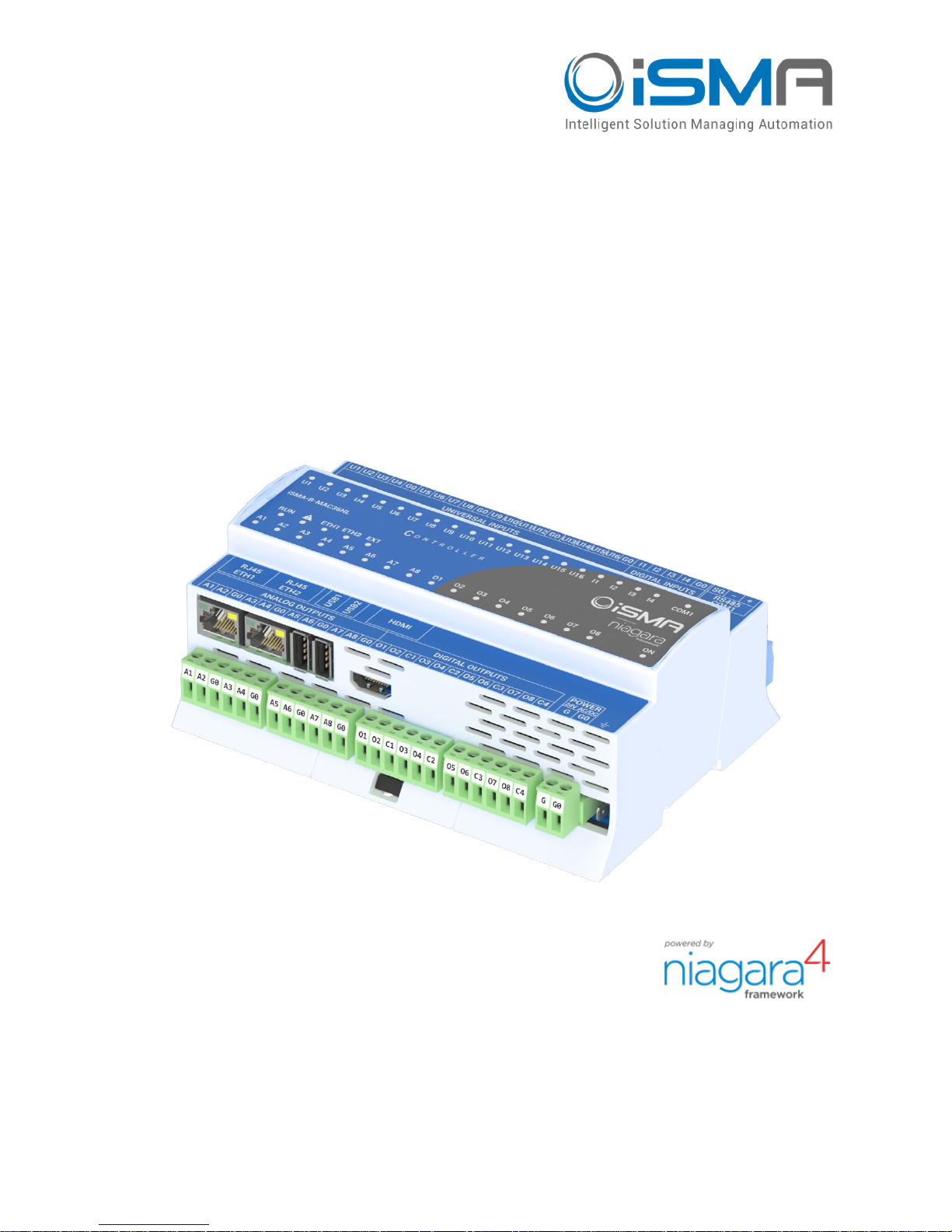
iSMA-B-MAC36NL
User Manual
Install and Start-up
Global Control 5 Sp. z o.o.
Warsaw, Poland
www.gc5.pl
Page 2

iSMA-B-MAC36NL
Version 1.0 www.gc5.pl Page 2 / 40
Table of contents
1 Introduction............................................................................................................................... 3
1.1 Revision history ................................................................................................................ 3
1.2 Safety rules ........................................................................................................................ 3
1.3 Overview ............................................................................................................................. 4
1.4 Key Features: ..................................................................................................................... 4
1.5 Technical specification ................................................................................................... 6
1.6 Software license notice ................................................................................................... 7
1.7 Dimensions ........................................................................................................................ 8
2 Hardware Specification .......................................................................................................... 9
2.1 Terminals and Internal Connection Diagram .............................................................. 9
2.2 Power Supply Connection ............................................................................................ 10
2.2.1 Earth Grounding ...................................................................................................... 11
2.3 Communication Bus Connection (RS485) ................................................................ 11
2.3.1 RS485 Grounding and Shielding .......................................................................... 11
2.3.2 RS485 Network Termination and Biasing .......................................................... 12
2.4 LED Indicators ................................................................................................................. 15
2.5 Mini USB ........................................................................................................................... 16
2.6 Local I/O ........................................................................................................................... 17
2.6.1 Universal Inputs (16x UI) ....................................................................................... 17
2.6.2 Digital Inputs (4x DI) ............................................................................................... 20
2.6.3 Analog Outputs (8x AO) ......................................................................................... 21
2.6.4 Digital Outputs (8x DO) .......................................................................................... 23
3 Start-up .................................................................................................................................... 24
3.1 Before the start ............................................................................................................... 24
3.2 SD Card ............................................................................................................................. 24
3.3 Factory settings .............................................................................................................. 26
3.3.1 Factory communication settings ......................................................................... 26
3.3.2 Factory platform credentials ................................................................................ 26
3.4 First login to the controller platform in Workplace .................................................. 27
3.5 TCP/IP Configuration .................................................................................................... 30
3.6 Connection to the console ............................................................................................ 35
3.7 Controller system update ............................................................................................. 36
3.8 Restore controller to the default state ....................................................................... 39
Page 3
iSMA-B-MAC36NL
Version 1.0 www.gc5.pl Page 3 / 40
1 Introduction
1.1 Revision history
Rev
Date
Description
1.0
01.10.2018
First edition
Table 1 - Revision history
1.2 Safety rules
• Note: Incorrect wiring of this product can cause its damage and may result in other
hazards. Make sure the product has been correctly wired before turning the power ON.
• Before wiring or removing / mounting the product, be sure to turn the power OFF. Failure
to do so might cause electric shock.
• Do not touch electrically charged parts such as the power terminals. Doing so might
cause electric shock.
• Do not disassemble the product. Doing so might cause electric shock or faulty
operation.
• Use the product within the operating ranges recommended in the specification
(temperature, humidity, voltage, shock, mounting direction, atmosphere etc.). Failure to
do so might cause fire or faulty operation.
• Tighten the wires firmly to the terminal. Insufficient tightening of the wires to the
terminal might cause fire.
Page 4

iSMA-B-MAC36NL
Version 1.0 www.gc5.pl Page 4 / 40
1.3 Overview
The iSMA-B-MAC36NL is a compact Master Application Controller with built-in different types
of I/O and operating in Niagara Framework environment. Using the specific local I/O set 16x
UI, 8x AO, 4x DI and 8x DO allows to use the device in different applications. The Controller
provides control, data logging, alarming, scheduling, integration and visualisation.
To allow IP connectivity there are 2x Fast Ethernet ports which operate as two independent
ports. Built-in 1x RS485 can be used to expand the number of I/O by connecting MINI or MIX
series I/O modules or to integrate with other subsystems.
Dedicated microSD card stores real-time data, history and alarms as well as Operating
System, Niagara Framework and licenses.
There are 2x USB ports, one of them operates as a host and the other one in OTG mode.
1.4 Key Features:
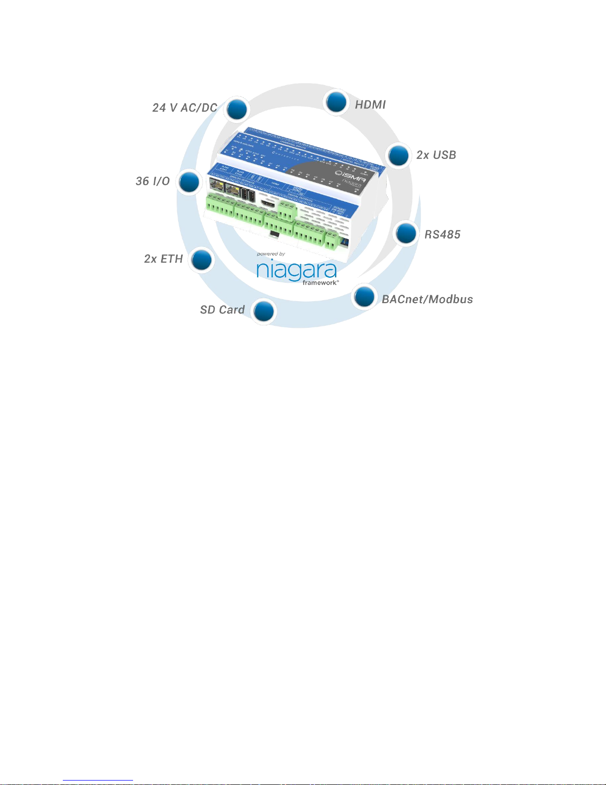
• Niagara 4.4 and later
• Real-time programming
• 2x Fast Ethernet (independent)
• 1x RS485 (opto-isolated), optional extension as second RS485 port
• 2x USB (1x OTG, 1x Host) (
support in the next release
)
• 16x UI, 8x AO, 4x DI and 8x DO
• HDMI to connect external display (
support in the next release
)
• Built-in Web server provides graphical user interface available from Web browser level
• SD card to collect real-time data, history and alarms
• Hardware replacement by SD Card
• Different licensing models for various application types
Page 5
iSMA-B-MAC36NL
Version 1.0 www.gc5.pl Page 5 / 40
Figure 1 – iSMA-B-MAC36NL Key Features
Page 6
iSMA-B-MAC36NL
Version 1.0 www.gc5.pl Page 6 / 40
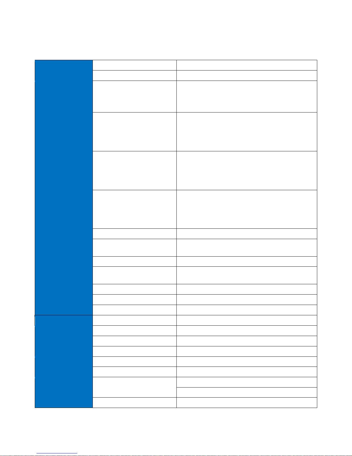
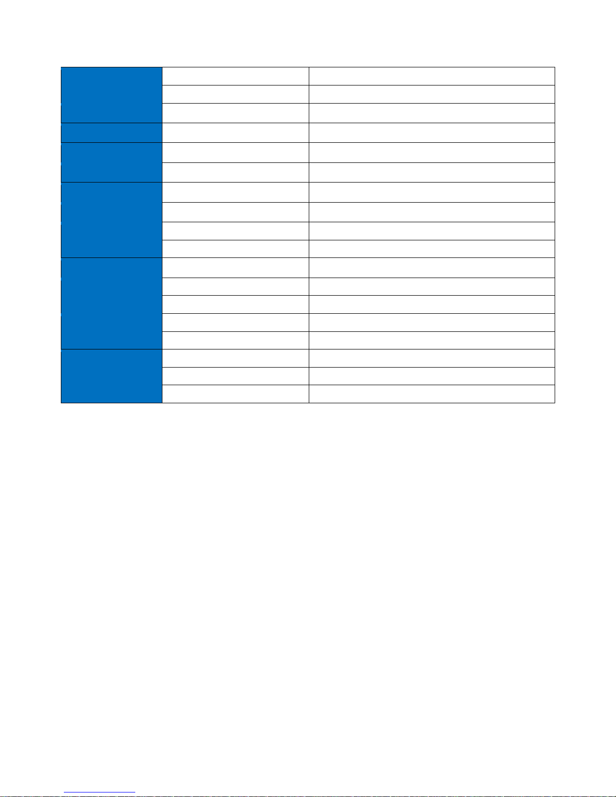
1.5 Technical specification
Power Supply
Voltage
24 V AC/DC ± 20% isolated
Power consumption
14 W @ 24 V DC; 24 VA @ 24 V AC
Universal Inputs
Temperature input
• Measurement with attached RTDs
• Accuracy ±0,1˚C
• For sensor Pt1000 and Ni1000 use 16-bit
resolution
Voltage input
• Voltage measurement from 0 - 10 V
• Input impedance 100 kΩ
• Measurement accuracy ±0,1%
• Measurement resolution 3 mV@12-bit and
1 mV@ 16-bit
Current input
• Current measurement 0 - 20 mA
• Required external resistor 200 Ω
• Measurement accuracy ±1,1%
• Measurement resolution 15 µA @ 12-bit and 5 µA
@ 16-bit
Resistive input
• Measurement of resistance from 0 to 1000 kΩ
• Measurement resolution for 20 kΩ load 20 Ω@12-
bit and 1 Ω@16-bit
• Measurement resolution for PT1000 and NI1000
0,1Ω@16bit
Resistance measurement method
The voltage divider
Dry contact input
Output current ~1 mA
Switching threshold: ON <5kΩ, OFF >8kΩ
Measurement resolution
12-bits (default) or 16-bits
Processing time
• 10 ms/channel @ 12-bits
• 140 ms/channel @ 16-bits
Digital Inputs
Type
Dry contact
Switching threshold
ON <5kΩ, OFF >8kΩ
Max input frequency
100 Hz
Analog Outputs
Voltage range
0 to 10 V DC
Max. load current
20 mA
Resolution
12-bits
Accuracy
±0.5%
Digital Outputs
(relays)
Contact material
AgSnO2
Resistive load
3 A @ 230 V AC/30 V DC
RS485 Interface
(base and optional)
RS485
Up to 128 devices
Half-duplex, Opto-isolated
Communication protocols
Modbus RTU/ ASCII
Page 7
iSMA-B-MAC36NL
Version 1.0 www.gc5.pl Page 7 / 40
Baud rate
From 2400 to 115,200
Address
1 to 247
Ethernet
2x Fast Ethernet
independent mode
Baud rate
10/100 Mb/s
USB
2x USB
1x OTG, 1x Host
HDMI
1x HDMI
Standard type A
SD Card
1x microSD
2 GB system reserved / 2 GB user storage
Ingress protection
IP
IP40
Temperature
Storage
-40˚C to +85˚C (-40˚F to +185˚F)
Operating
-10˚C to +50˚C (14˚F to +122˚F)
Humidity
Relative
5% to 95% RH
Connectors
Type
Removable screw terminals
Maximum cable size
2.5 mm2
Housing
Construction
UL approved, self-extinguishing plastic (PC/ABS)
Mounting
DIN (DIN EN 50022 norm)
Dimension
Width
111 mm (4,4’’)
Length
160 mm (6,3’’)
Height
62 mm (2,45’’)
Table 2 – Technical Specification
1.6 Software license notice
This product contains code covered by the GNU General Public License (GPL).
Page 8
iSMA-B-MAC36NL
Version 1.0 www.gc5.pl Page 8 / 40
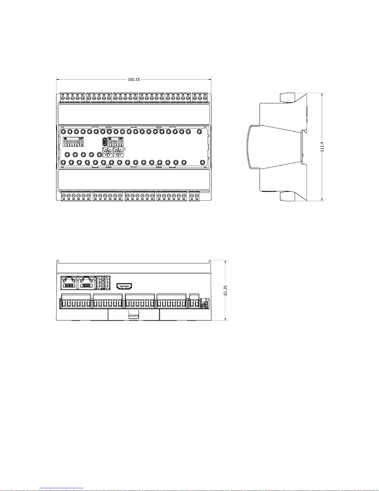
1.7 Dimensions
Figure 2 – iSMA-B-MAC36NL Dimensions [mm]
Page 9
iSMA-B-MAC36NL
Version 1.0 www.gc5.pl Page 9 / 40
2 Hardware Specification
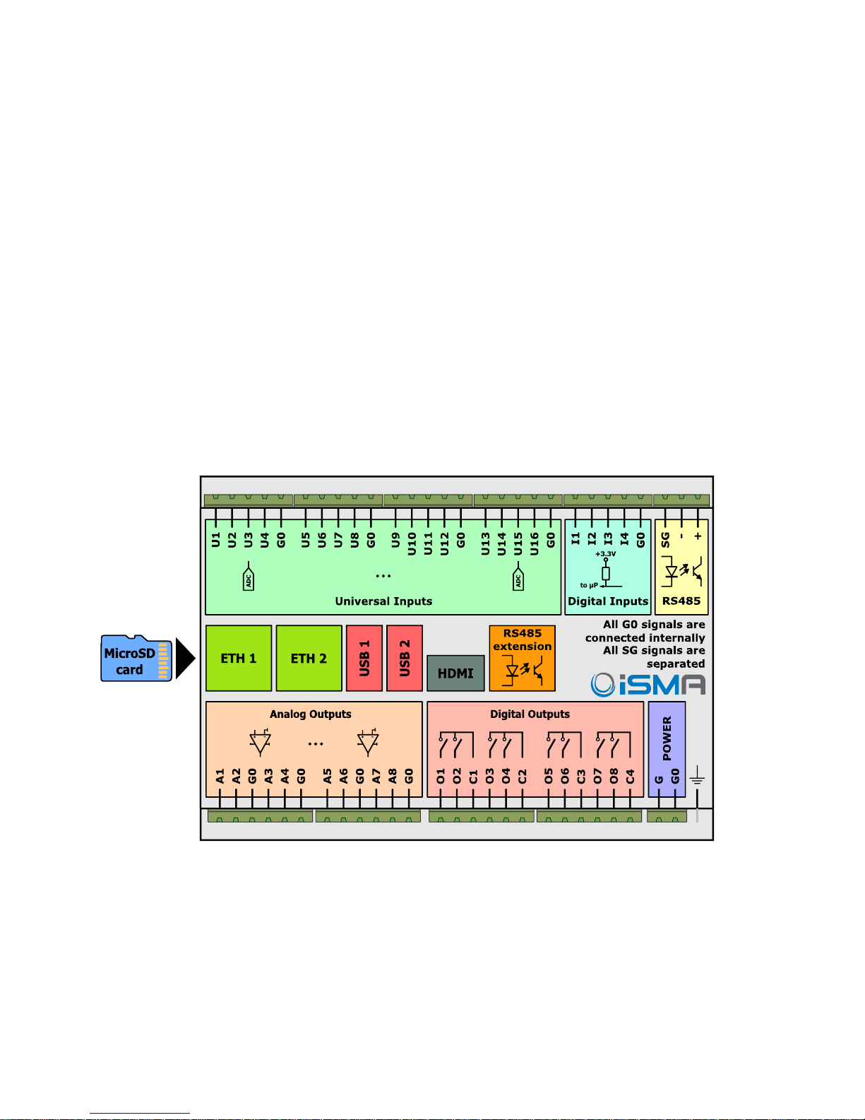
2.1 Terminals and Internal Connection Diagram
The iSMA-B-MAC36NL controller can be supplied by 24 V AC/DC. The power supply block is
separated. The grounding pin located next to power supply terminals must be connected to
the ground.
The device has 36x local IO on board:
• 8x Digital Outputs (8DO), relay output with max. load 3 A @ 230 V AC/30 V DC.
• 8x Analog Outputs (8AO), voltage output 0-10 V DC maximum load up to 20 mA.
• 16x Universal Inputs (16UI), temperature, voltage, current, resistive or dry contact.
• 4x Digital Inputs (4DI), dry contact inputs or fast counter up to 100 Hz.
Figure 3 – iSMA-B-MAC36NL Block Diagram
Page 10
iSMA-B-MAC36NL
Version 1.0 www.gc5.pl Page 10 / 40
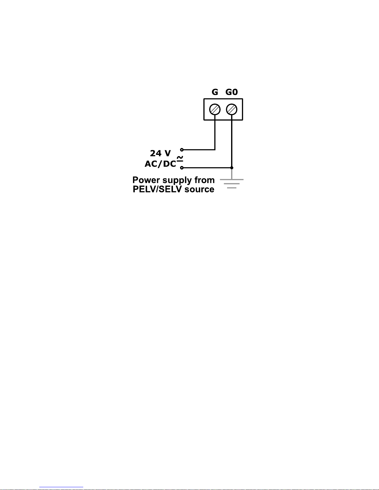
2.2 Power Supply Connection
The device is designed to work with 24 V AC/DC separated power supply.
Figure 4 24 V AC/DC power supply connection
Page 11
iSMA-B-MAC36NL
Version 1.0 www.gc5.pl Page 11 / 40
2.2.1 Earth Grounding
Earth grounding provides protection from electrostatic discharge or other forms of EMI.
The way to connect the controller’s ground spade lug to a nearby earth ground is shown in the
figure below.
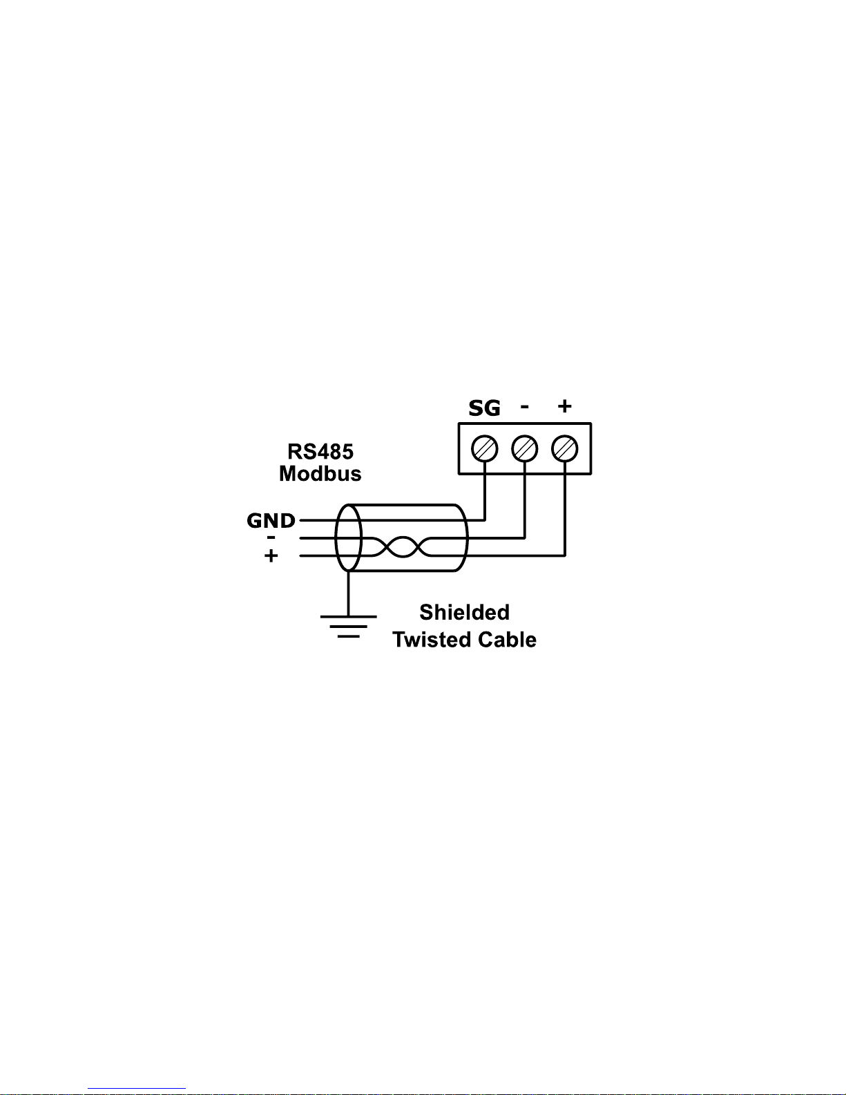
2.3 Communication Bus Connection (RS485)
The device is equipped with opto-isolated RS485 base port, which allows to connect the device
to the BMS in order to communicate with other devices in the network. The optional controller
version has an extension as second RS 485 port. All rules are the same as in the base port.
The way of proper bus cable connection is shown in the figure below.
Figure 6 RS485 communication bus connection
2.3.1 RS485 Grounding and Shielding
The device can be exposed to electromagnetic environment. The electromagnetic radiation
can induce electrical noise into both power and signal lines, as well as direct radiation into the
device causing negative effects to the device functioning. Appropriate grounding, shielding
and the other protective steps should be taken at the installation stage to prevent undesirable
effects. The preventions include making control cabinets grounding, cables shield grounding,
using protective elements for electromagnetic switching devices, using correct wiring as well
as appropriate cable types selection and cable cross sections.
Page 12
iSMA-B-MAC36NL
Version 1.0 www.gc5.pl Page 12 / 40
2.3.2 RS485 Network Termination and Biasing
The transmission line often creates communication problems. These problems include
reflections and signal attenuation.
To eliminate the presence of reflections at the ends of the bus cable, it must be terminated
at both ends with a resistor across the line. The resistor value has to be the same as a
characteristic impedance of the bus cable. Both ends must be terminated since the
direction of propagation is bidirectional. In the case of an RS485 twisted pair cable the
termination is typically 120 Ω.
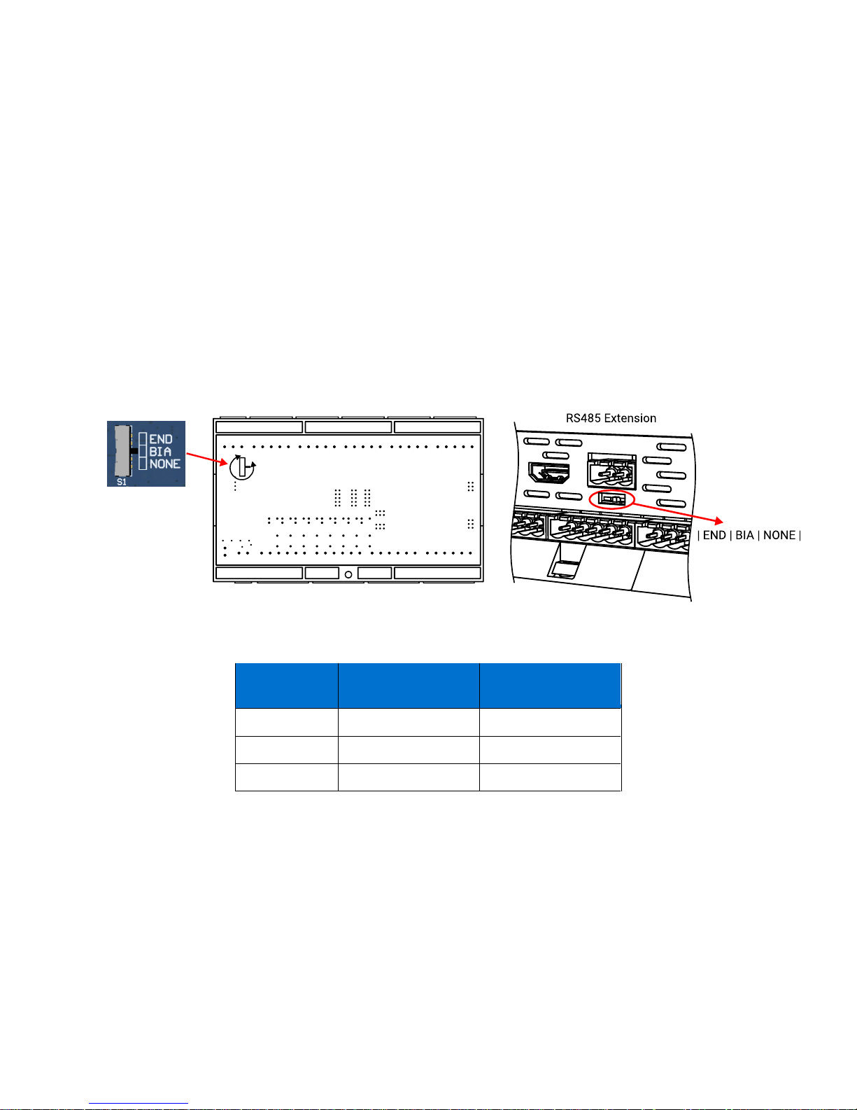
In the iSMA-B-MAC36NL version there is a built-in 3 position Switch on the back side of the
device (access after removing the back cover) which is dedicated to connect termination
resistor and/or biasing resistors. In the iSMA-B-MAC36NL-RS version 3 position Switch is
a built-in below terminal connector as shown in the figure below on the right side.
Bottom side of controller
Figure 7 Switch for termination and biasing for base (on left) and optional extension port (on right)
Table 3 Switch Termination and biasing
Switch position
Biasing
Termination 120 Ω +
Biasing
END
OFF
ON
BIA
ON
OFF
NONE
OFF
OFF
Page 13
iSMA-B-MAC36NL
Version 1.0 www.gc5.pl Page 13 / 40
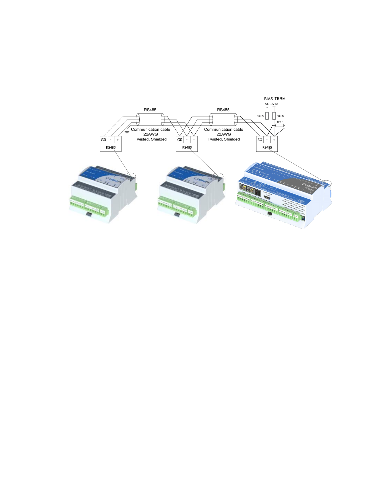
When the switch is in the END position it connects the termination resistor 120 Ω and biasing
resistors 680 Ω (pull-down to ground SG and pull-up to +5VDC) to the RS485 bus.
So instead of using additional resistors, the termination and biasing can be easily done by
simple switch activation.
Figure 8 RS485 network termination and biasing
Page 14
iSMA-B-MAC36NL
Version 1.0 www.gc5.pl Page 14 / 40
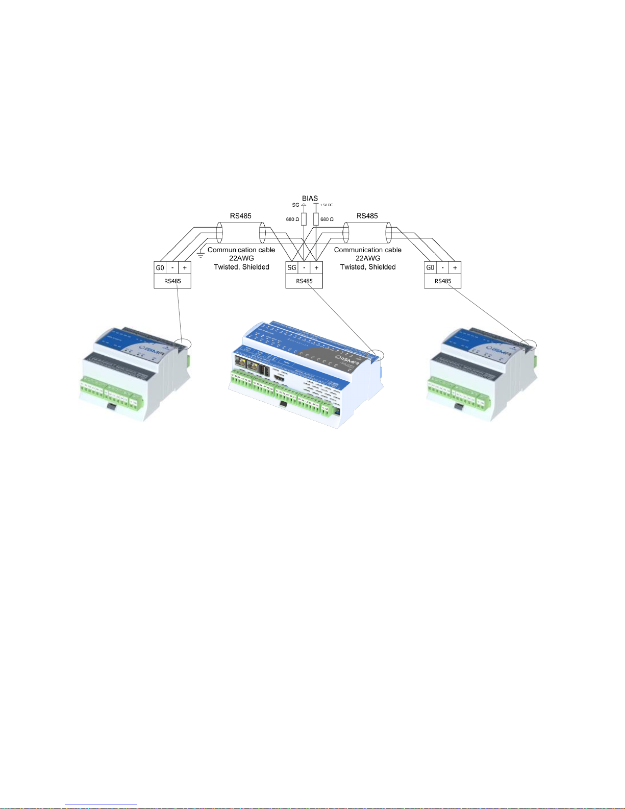
When the switch is in the BIA position it connects the biasing resistors 680 Ω (pull-down to
ground SG and pull-up to +5VDC) to the RS485 bus. The biasing is added to the RS485 bus in
order to reduce communication failures.
WARNING! Only one single device on the network can have biasing resistors connected.
Connecting biasing resistors on two or more devices on the one single RS485 bus will take an
opposite effect – increase the number of the communication problems.
Figure 9 RS485 network biasing
Page 15
iSMA-B-MAC36NL
Version 1.0 www.gc5.pl Page 15 / 40
2.4 LED Indicators
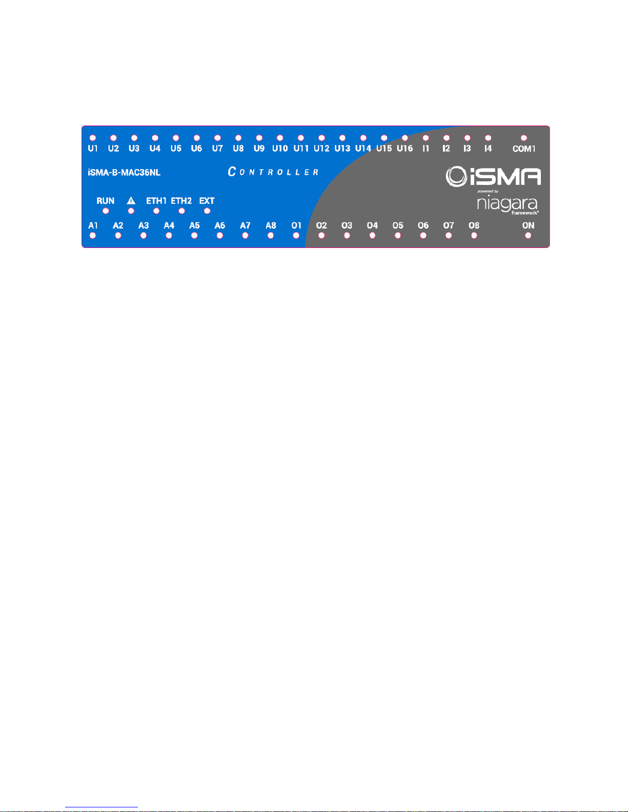
The device is equipped with LEDs for quick status checking and diagnostics:
Figure 10 LEDs on the front panel of iSMA-B-MAC36NL.
• The Power LED ON lights up (green) and then turns the power supply on.
• The Communication LED COM1 lights up (orange) for 20 ms in the transmit state for
sending each package through the main RS485 port. As long as the device sends
packages, the Communication LED blinks continuously.
• The Communication LED EXT lights up (orange) for 20 ms in the transmit state for sending
each package through the extension RS485 port. As long as the device sends packages,
the Communication LED blinks continuously.
• The Communication LEDs ETH1 and ETH2 light up (orange) in the transmit or receive state
when sending/receiving each packages through the particular Ethernet port. As long as
the device sends/receives packages, the Communication LEDs blink continuously.
• The Universal Inputs LEDs U1-U16 indicate the statuses of the Universal Inputs. When the
LED is ON, the resistance value connected to the input is lower than the switching
threshold value (Dry Contact input is active).
Note: The LED also lights up when voltage connected to the input has very low potential.
• The Digital Inputs LEDs I1-I4 indicate the statuses of the Digital Inputs. When the LED is
ON, the Input is active (resistance value connected to the input is lower than the switching
threshold value).
• The Analog Outputs LEDs A1-A8 indicate the statuses of the Analog Outputs. When the
LED is ON, the Output voltage or PWM factor is different than 0.
• The Digital Outputs LEDs O1-O8 indicate the statuses of the Digital Outputs. When the LED
is ON, the Outputs is active (closed circuit).
Page 16
iSMA-B-MAC36NL
Version 1.0 www.gc5.pl Page 16 / 40
• The Status LED RUN does not light when the power is connected. After Operating System
(Linux) has started up, the LED RUN lights up continuously (green). Next, after the Platform
has started up, the LED RUN also flashes very quickly. If a station exists in a controller,
after the station has been started up and it operates correctly, the LED RUN flashes slowly
(1Hz).
• The Alarm LED Δ (triangle with an exclamation mark) lights up in red color when there is
no SD Card inserted or there is a problem with SD Card connection/reading/writing.
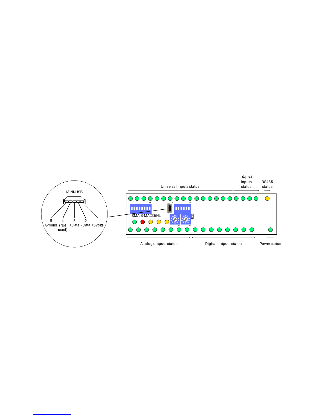
2.5 Mini USB
The mini USB port is dedicated to debugging connection through the console.
You can find a description of how to connect to the system console in Connection to the
console chapter.
Figure 11 LEDs on the front panel of iSMA-B-MAC36NL.
Page 17

iSMA-B-MAC36NL
Version 1.0 www.gc5.pl Page 17 / 40
2.6 Local I/O
The iSMA-B-MAC36NL has built-in different types of I/O. The specific local I/O set 16x UI, 8x
AO, 4x DI and 8x DO allows to use the device in different applications.
2.6.1 Universal Inputs (16x UI)
All the Universal Inputs have 16-bit ADC, which supports the following types of the input
signals:
• Voltage Input (0 – 10 V DC)
• Current Input (0 – 20 mA)
• Resistive Input (0-1000 kΩ)
• Temperature Input
• Dry Contact Input (Digital Input)
2.6.1.1 Voltage Input connection (0 – 10 V DC)
Figure 12 Connection of UI to measure voltage 0-10 V DC.
Page 18
iSMA-B-MAC36NL
Version 1.0 www.gc5.pl Page 18 / 40
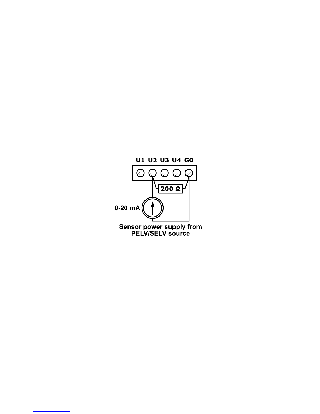
2.6.1.2 Current Input connection (0 – 20 mA)
Current measurement is realized by voltage measurement and 200 Ω resistance.
According to the Ohm’s law the current is directly proportional to the voltage and the
resistance is the constant of proportionality.
𝑰 =
𝑼
𝑹
According to the Ohm’s law equation for 20 mA current with 200 Ω resistance the output
voltage is 4 V.
It means that the 4 V voltage measured on the Universal Input corresponds to 20 mA current.
The result is expressed in millivolts.
Figure 13 Connection of UI to measure current 0-20 mA.
Page 19
iSMA-B-MAC36NL
Version 1.0 www.gc5.pl Page 19 / 40
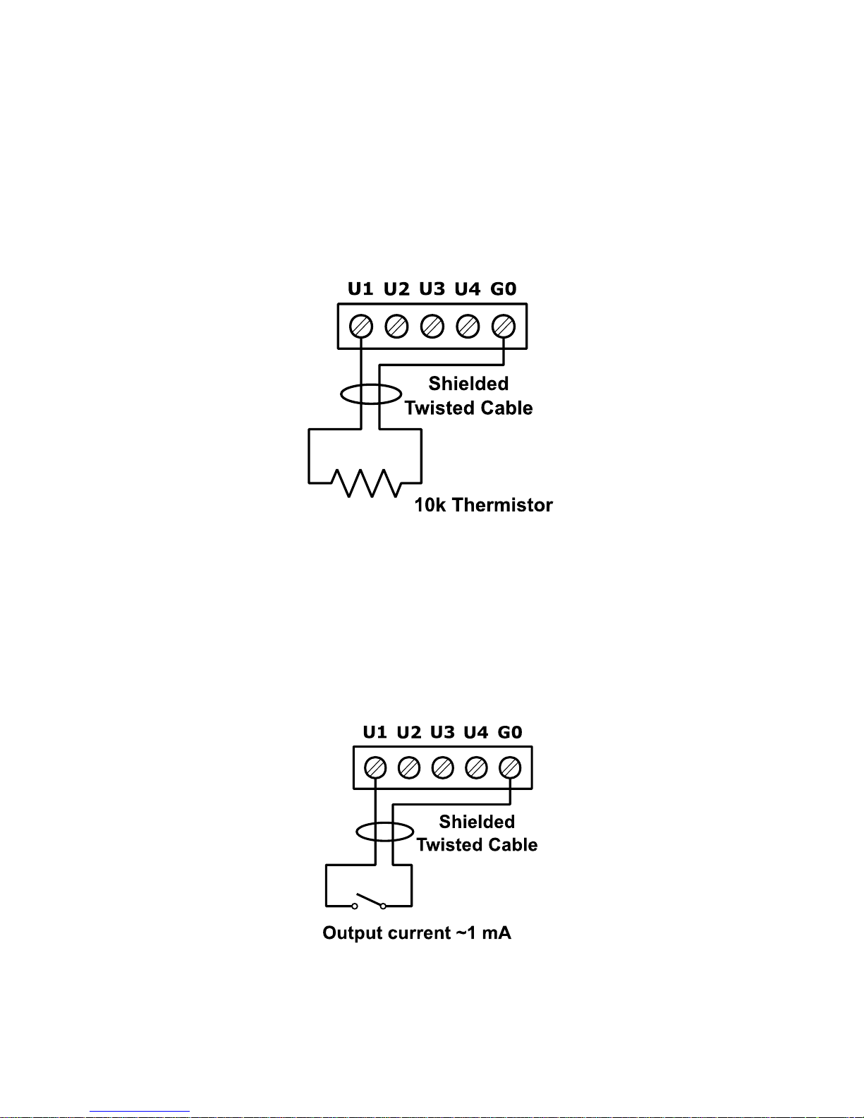
2.6.1.3 Temperature Input connection
Temperature measurement is based on resistance.
The Universal Inputs working as Temperature Inputs support the following types of sensors:
10K3A1, 10K4A1, Carel 10K, 20K6A1, 2.2K3A1, 3K3A1, 30K6A1, SIE1, TAC1, SAT1, Pt1000,
Ni1000.
Figure 14 Connection of UI to measure temperature
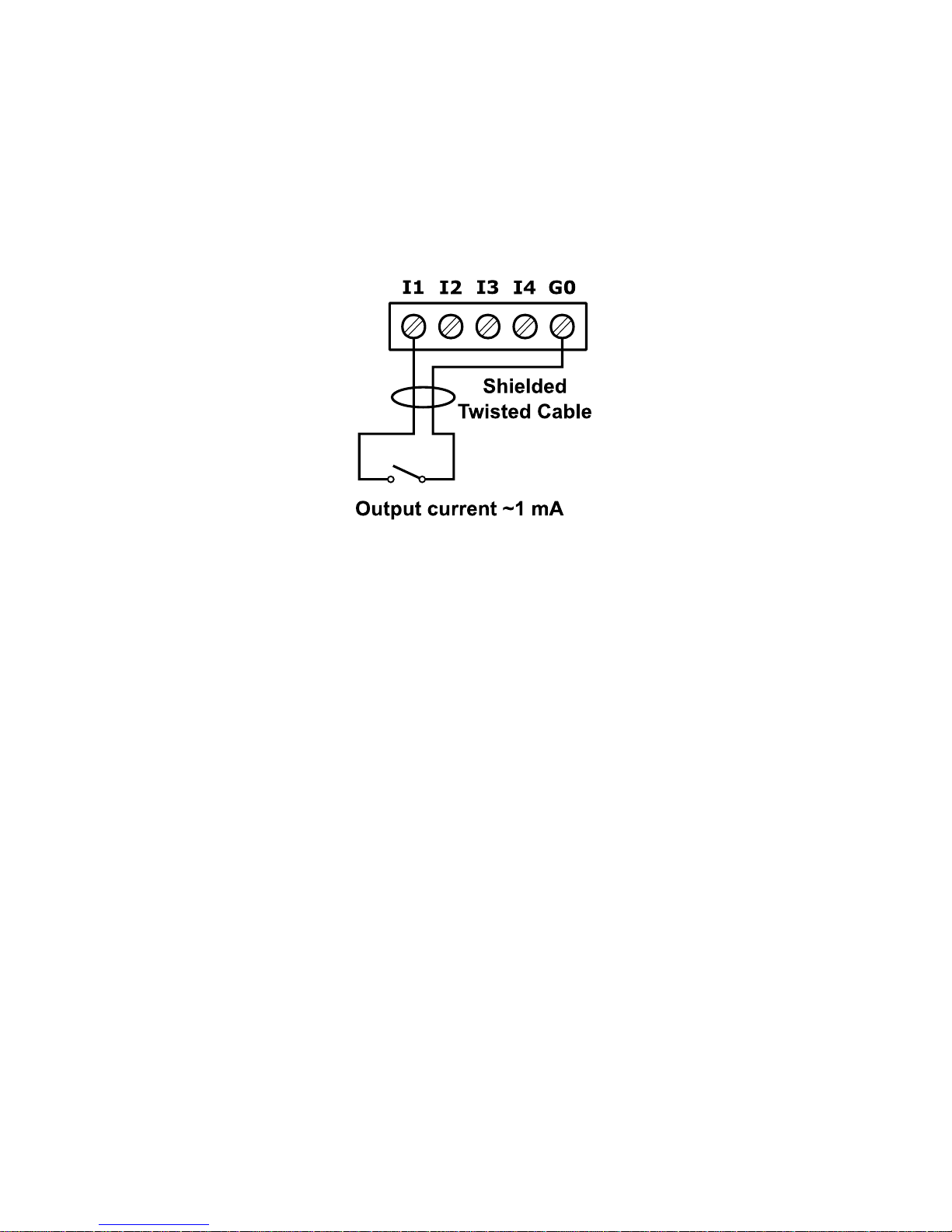
2.6.1.4 Dry Contact Input connection (Digital Input)
The Universal Inputs can operate as standard Digital Inputs (Dry Contact Inputs).
The Input is active when it is connected to the ground (G0).
Figure 15 Connection of UI as Dry Contact Input (Digital Input)
Page 20
iSMA-B-MAC36NL
Version 1.0 www.gc5.pl Page 20 / 40
2.6.2 Digital Inputs (4x DI)
In addition to the standard Dry Contact Input the Digital Inputs can operate as fast pulse
counters with up to 100 Hz impulse frequency counting.
The Input is active when it is connected to the ground (G0).
Figure 16 Connection to the Digital Input.
Page 21
iSMA-B-MAC36NL
Version 1.0 www.gc5.pl Page 21 / 40
2.6.3 Analog Outputs (8x AO)
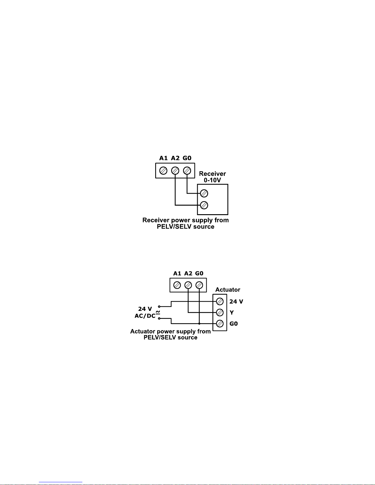
All the Analog Outputs have 12-bit ADC, provide 10 mV resolution and accuracy less than
±0,5%. They support the following types of the output signals:
• Voltage Output (0 – 10 V DC) with max. load up to 20 mA
• PWM: 0,01 Hz, 0,1 Hz, 1 Hz, 10 Hz, 100 Hz
2.6.3.1 Voltage Output connection (0 – 10 V DC)
Figure 17 Connection of the 0 – 10 V DC signal from the Analog Output.
2.6.3.2 Connection of an actuator 24 V AC/DC
Figure 18 Connection of the 0 – 10 V DC signal from the Analog Output.
Page 22
iSMA-B-MAC36NL
Version 1.0 www.gc5.pl Page 22 / 40
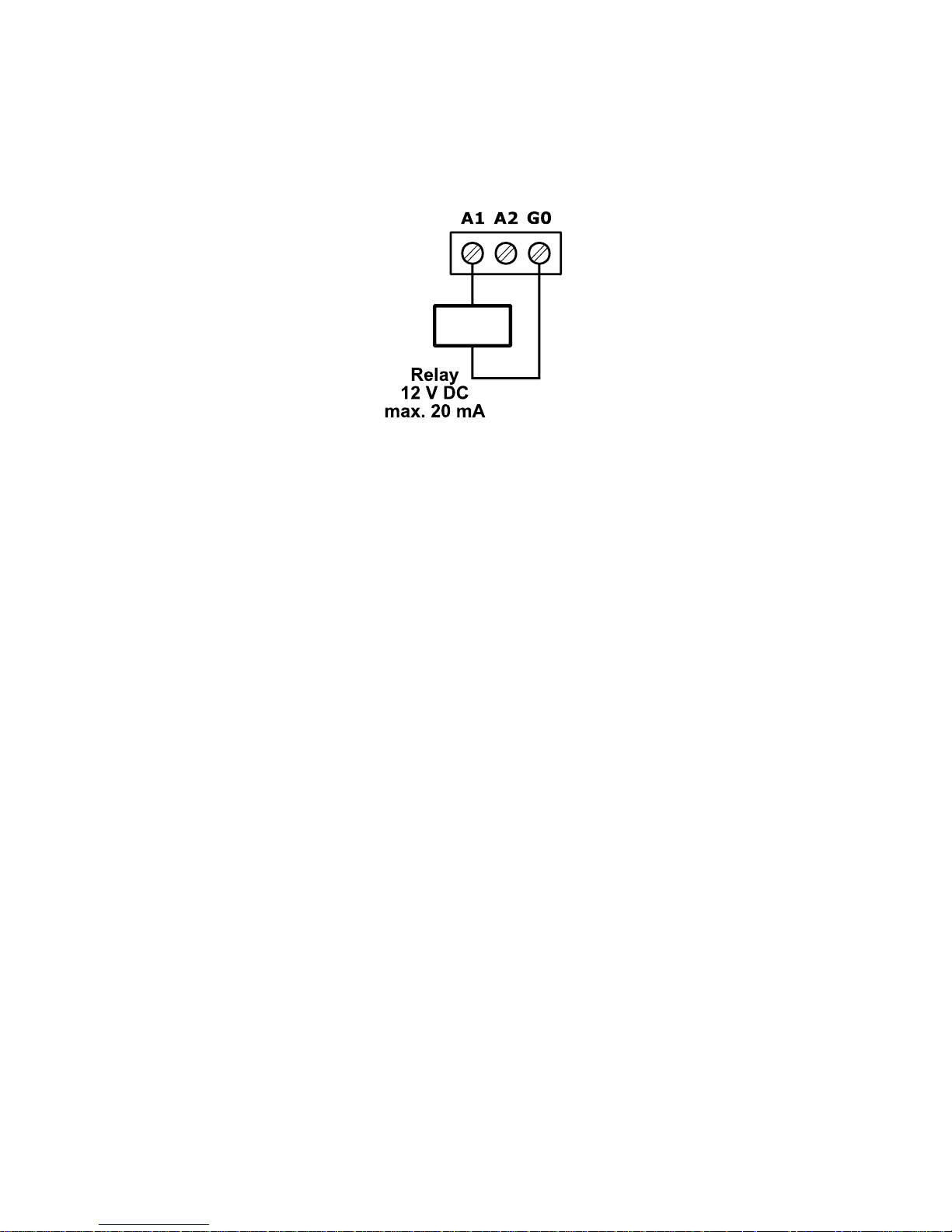
2.6.3.3 Relay to Analog Output connection
There is an option to control the 12 V DC relay from the Analog Outputs (max. load cannot
exceed 20 mA!).
Figure 19 Relay connection to the Analog Output.
Page 23
iSMA-B-MAC36NL
Version 1.0 www.gc5.pl Page 23 / 40
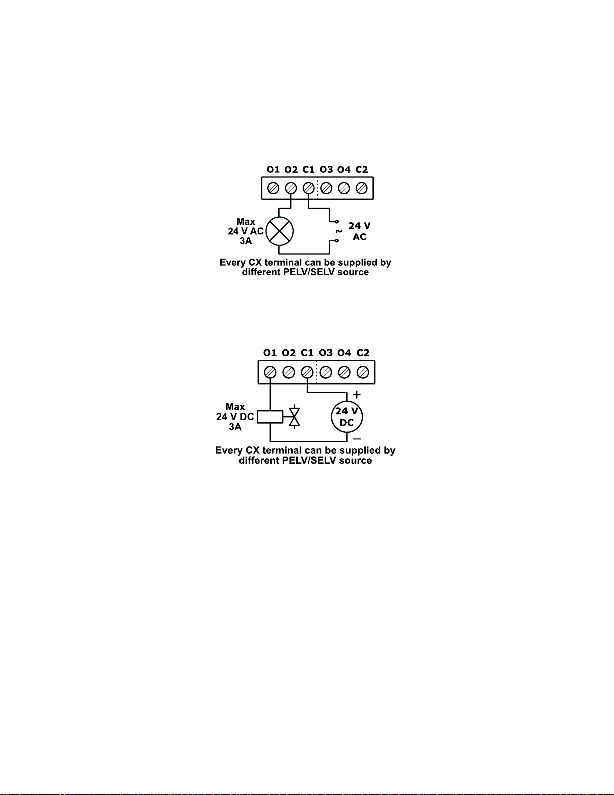
2.6.4 Digital Outputs (8x DO)
Relay Outputs (NO) have max. resistive load up to 3 A @ 30 V DC and up to 3 A @ 230 V AC..
2.6.4.1 Resistive Load connection
Figure 20 Connection of the resistive load to the Digital Output.
2.6.4.2 Solenoid Valve connection
Figure 21 Connection of the solenoid valve to the Digital Output.
Page 24

iSMA-B-MAC36NL
Version 1.0 www.gc5.pl Page 24 / 40
3 Start-up
3.1 Before the start
To be able to operate normally the device needs to have the following:
1. SD Card
2. License assigned
Hardware itself is only the base for SD Card which consists all the software parts needed for
hardware management.
SD Card is not assigned with a particular hardware unit. It can be moved to another hardware.
This function allows easy hardware replacement. Together with SD Card all the parameters
such as Communication Settings, station, Niagara, JVM and Operation System are moved.
License file provides limited number of points which can be used to build your application.
Without the license file user is not allowed to run the station on the device.
3.2 SD Card
Without the microSD Card it is impossible for the device to operate properly.
MicroSD Card contains all main software parts which are crucial for the device functioning:
1. Linux Operating System
2. Java Virtual Machine
3. Niagara N4
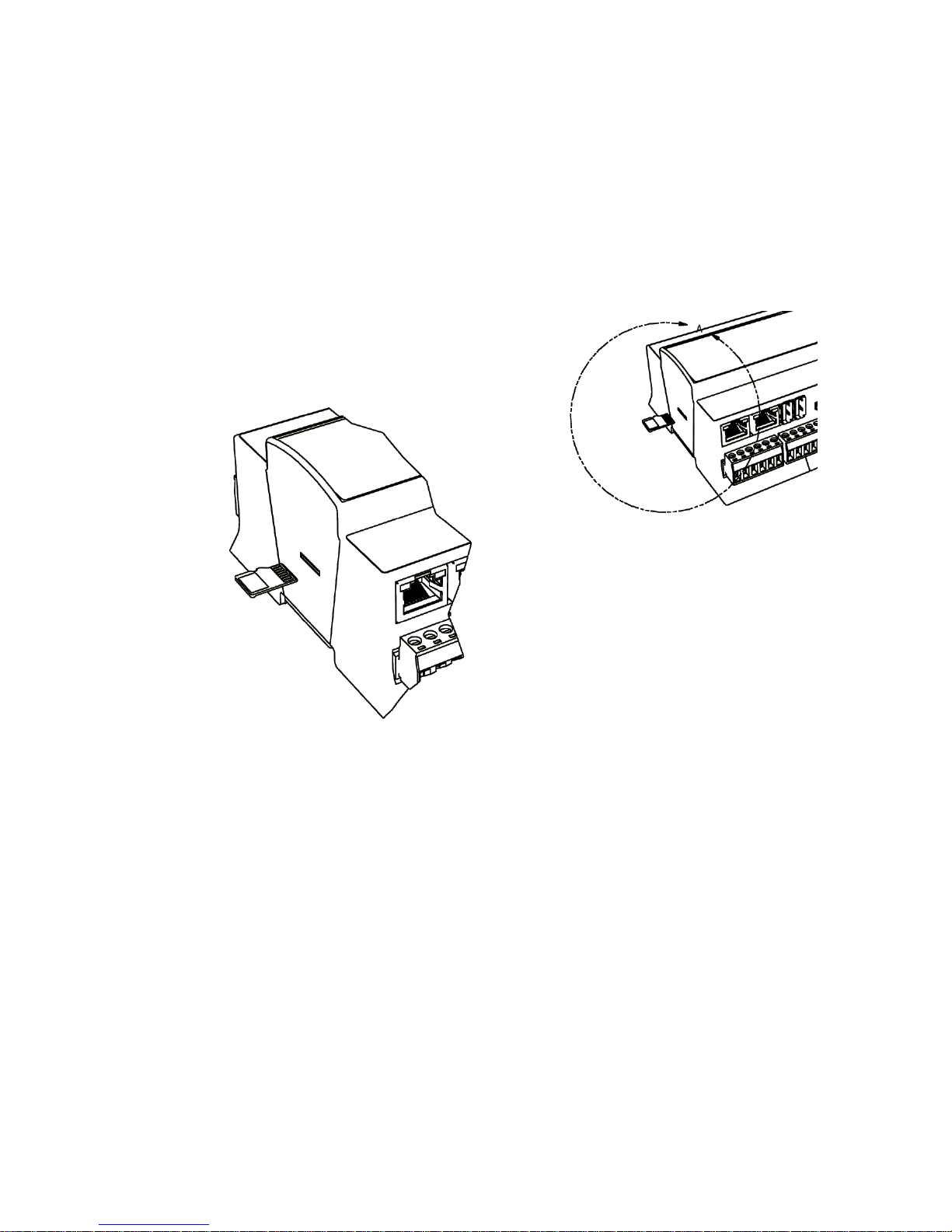
The Card slot is placed on the left side of the device as it is shown in the figure below
The micro SD card must be inserted into the unit prior to the mounting process. However, it is
possible to move an SD card from one unit to another (microSD Card is not assigned with the
particular hardware iSMA-B-MAC36NL unit). For example, you might want to remove the SD
card from a unit that suffered a hardware failure and use it in a replacement unit.
Prerequisites:
Page 25
iSMA-B-MAC36NL
Version 1.0 www.gc5.pl Page 25 / 40
All power to the controller needs to be shut down before inserting/removing the microSD card,
otherwise equipment damage may occur.
The controller needs to be unmounted from any DIN rail or screw tab mounting, as accessing
the card uses space behind the mounting base.
Discharge any static electricity that you may have accumulated by touching a known, securely
grounded object.
Figure 22 SD Card Mounting
Insert the micro SD card by sliding the card into the card socket, label side down, until the
spring catch engages. If properly inserted, the card is behind the shutter track.
Remove the micro SD card by pushing the card in, until the spring release pushes the card
partially out of the card socket. Grasp the card and pull it completely out of the unit. Store the
micro SD card in a static free protective case.
Page 26

iSMA-B-MAC36NL
Version 1.0 www.gc5.pl Page 26 / 40
3.3 Factory settings
Out of the box the SD Card Image has the factory settings. Every time when the controller is
restored via clean or update distribution file, the default settings are restored. Please refer to
the Controller System Update chapter for more details.
WARNING! The cleaning deletes the station – please save it before update!
The factory settings can be divided into two groups:
3.3.1 Factory communication settings
• IP Address: 192.168.1.123
• Subnet Mask: 255.255.255.0
• Default Gateway: 192.168.1.1
• Nameserver (DNS): 192.168.1.1
• Host Name : MACNL
3.3.2 Factory platform credentials
• User: tridium
• Password: niagara
Note: In Niagara 4.4 version User is requested to change the factory platform credentials at
the first platform logging.
Out of box the controller has no default station installed.
Page 27

iSMA-B-MAC36NL
Version 1.0 www.gc5.pl Page 27 / 40
3.4 First login to the controller platform in Workplace
After opening the Workplace Software to log into the controller for the first time please do the
following steps:
From the menu bar, click File > Open > Open Platform.
The Open Platform window appears.
Fill the fields in the Open Platform window as follows:
Type — Select Image Platform Connection, if not already selected.
NOTE: Workbench may default to a secure Image Platform TLS Connection. If so, for any new
controller, change type to a regular (non-TLS) platform connection. After conversion, you
should always use the recommended TLS platform connection.
Host — Leave at default IP, and type in the default IP address of the new controller (the default
IP address is 192.168.1.123).
Port — Leave at default 3011.
Credentials:
Username — Type in the factory default User name (tridium)
Password — Type in the factory default password (niagara)
Click the OK button to accept all settings.
Page 28
iSMA-B-MAC36NL
Version 1.0 www.gc5.pl Page 28 / 40
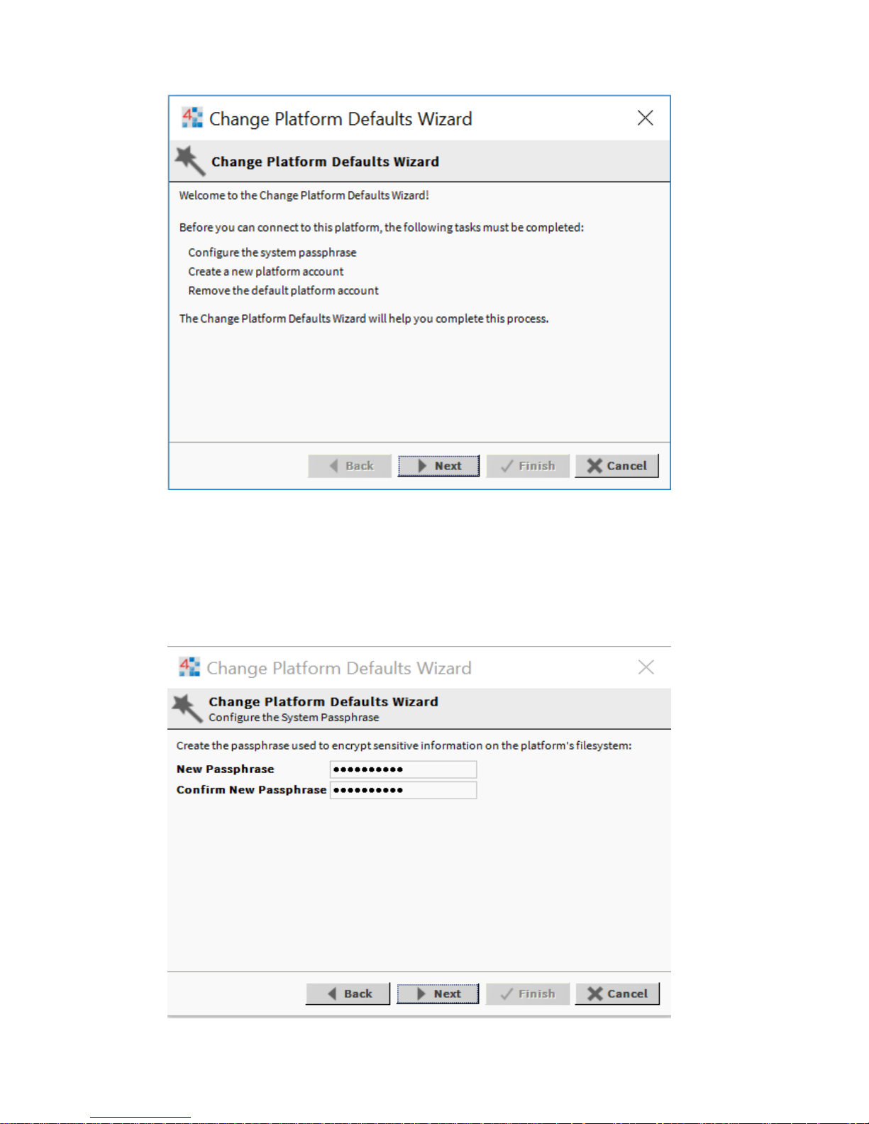
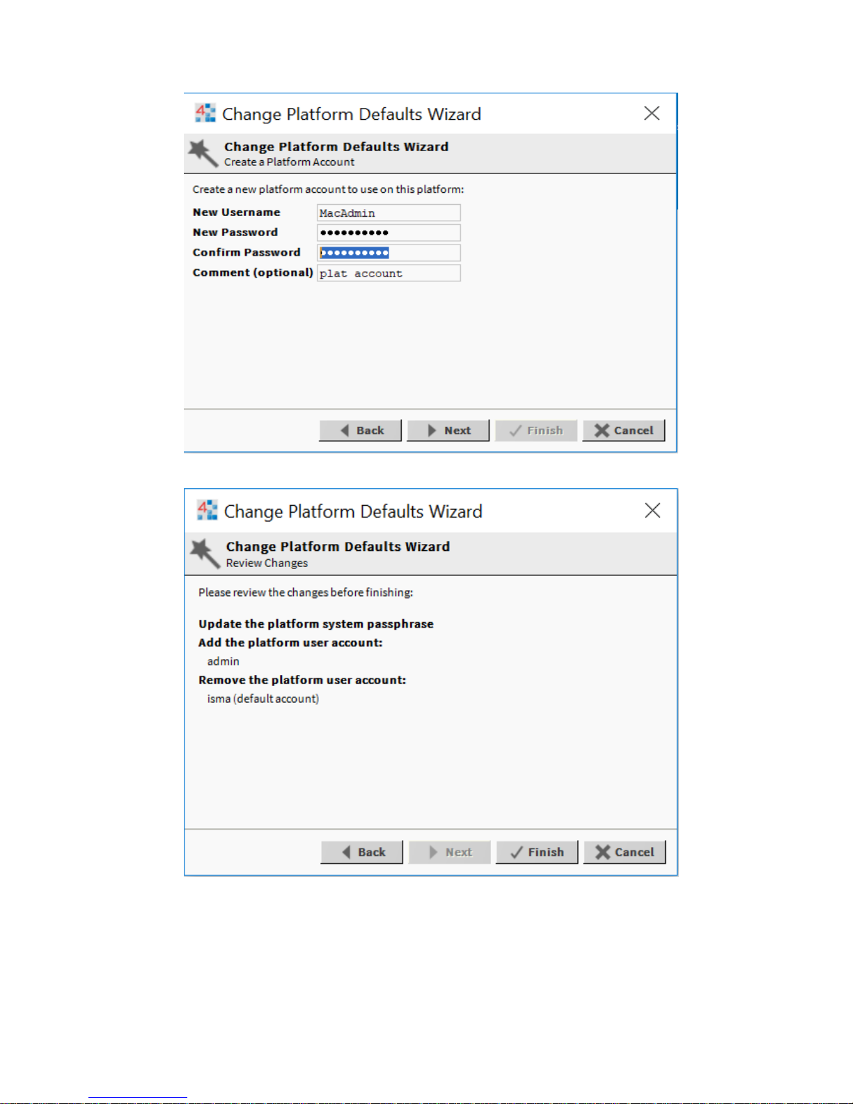
If the Change Platform Defaults Wizard displays, click Next to step through creating a system
passphrase, creating a new platform account, and removing the default platform account, as
shown below.
Page 29
iSMA-B-MAC36NL
Version 1.0 www.gc5.pl Page 29 / 40
Click Finish to complete these changes.
The system completes making the connection between the host and Workbench, and displays
the Nav Container View.
Page 30
iSMA-B-MAC36NL
Version 1.0 www.gc5.pl Page 30 / 40
3.5 TCP/IP Configuration
TCP/IP Configuration is one of several platform views. Typically, you use it to initially configure
a remote controller’s TCP/IP settings.
Configuring TCP/IP communication settings is a task for the systems integrator while initially
setting up a controller.
Perform the following steps:
Open a connection to the platform.
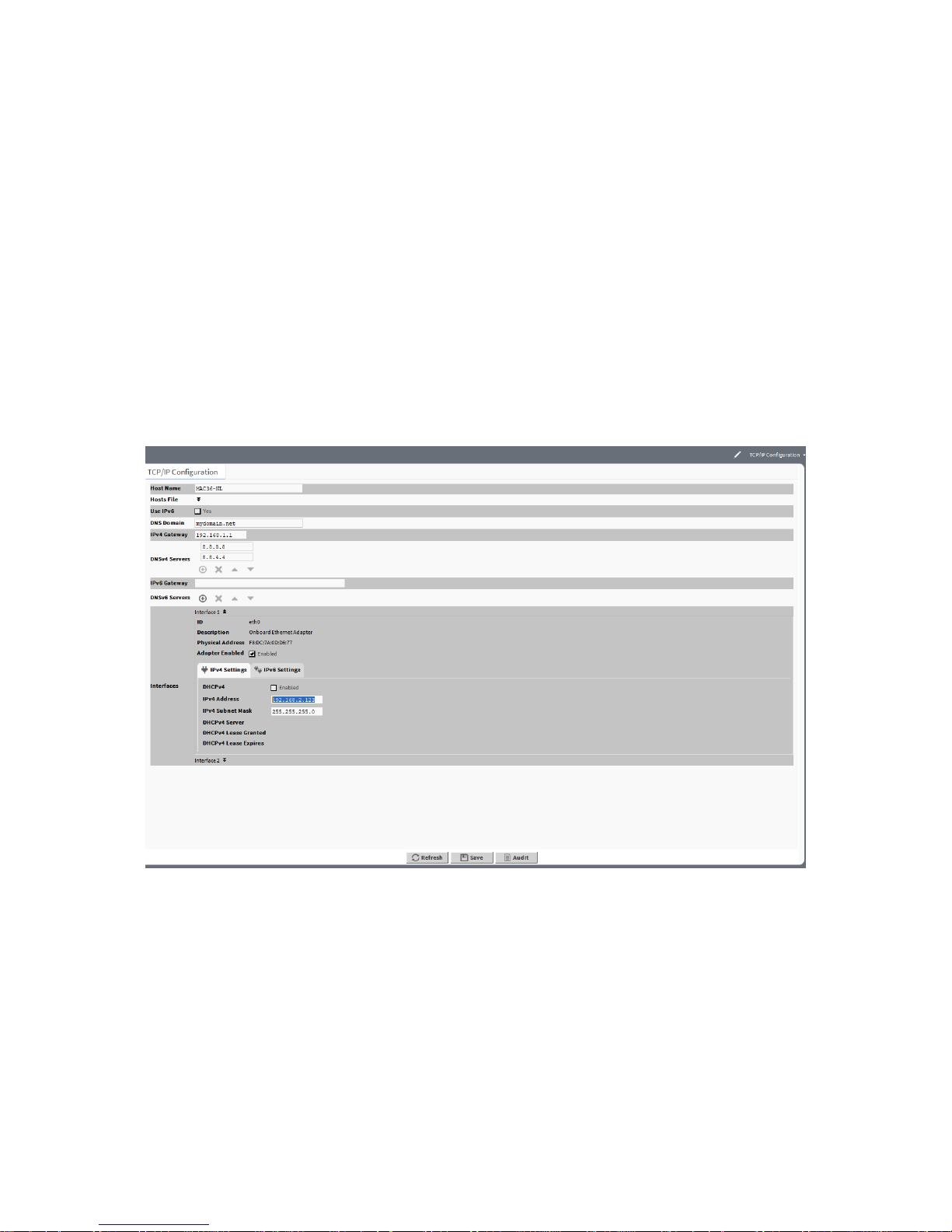
Expand the Platform container in the Navigation tree and double-click the TCP/IP
Configuration container.
Click the drop-down arrows to expand a group of properties.
Page 31
iSMA-B-MAC36NL
Version 1.0 www.gc5.pl Page 31 / 40
For each Ethernet port on the connected platform, the TCP/IP Configuration platform view
provides an expandable Interface in Image section.
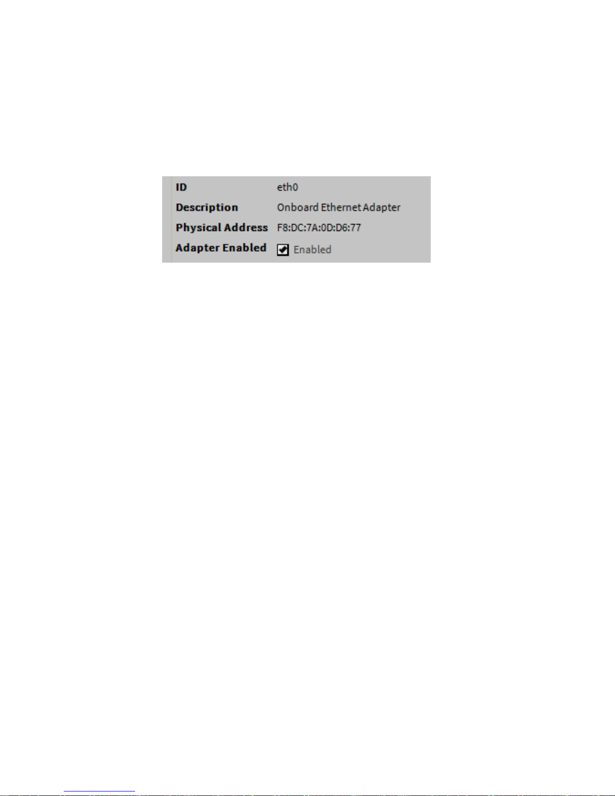
All compatible iSMA-B-MAC36NL controllers have two Ethernet ports: ETH1 and ETH2. In the
TCP/IP Configuration view, they are listed as Interface 1 (eth0) and Interface 2 (eth1).
As shown above, each Interface has the following properties at the top:
ID
A read-only OS identifier for the hardware interface, such as “eth0” for a iSMA-B-MAC36NL
controller, or, for a Windows platform, either a 128-bit GUID (globally unique identifier) or a
Windows network connection name, such as “Local Area Connection 2”.
Description
A read-only text string such as “Onboard Ethernet Adapter eth0” for a iSMA-B-MAC36NL
controller, or i.e. “Intel(R) PRO/100 VE Network Connection” for a Win32-based host,
describing a NIC model.
Physical Address
The unique 48-bit MAC address of the Ethernet adapter, in six two-hexadecimal digits. For
example, for the “eth0” Interface 1 port of a iSMA-B-MAC36NL controller: F8:DC:7A:0D:D6:77
Adapter Enabled
Checkbox to specify whether the Ethernet port is usable.
Page 32
iSMA-B-MAC36NL
Version 1.0 www.gc5.pl Page 32 / 40
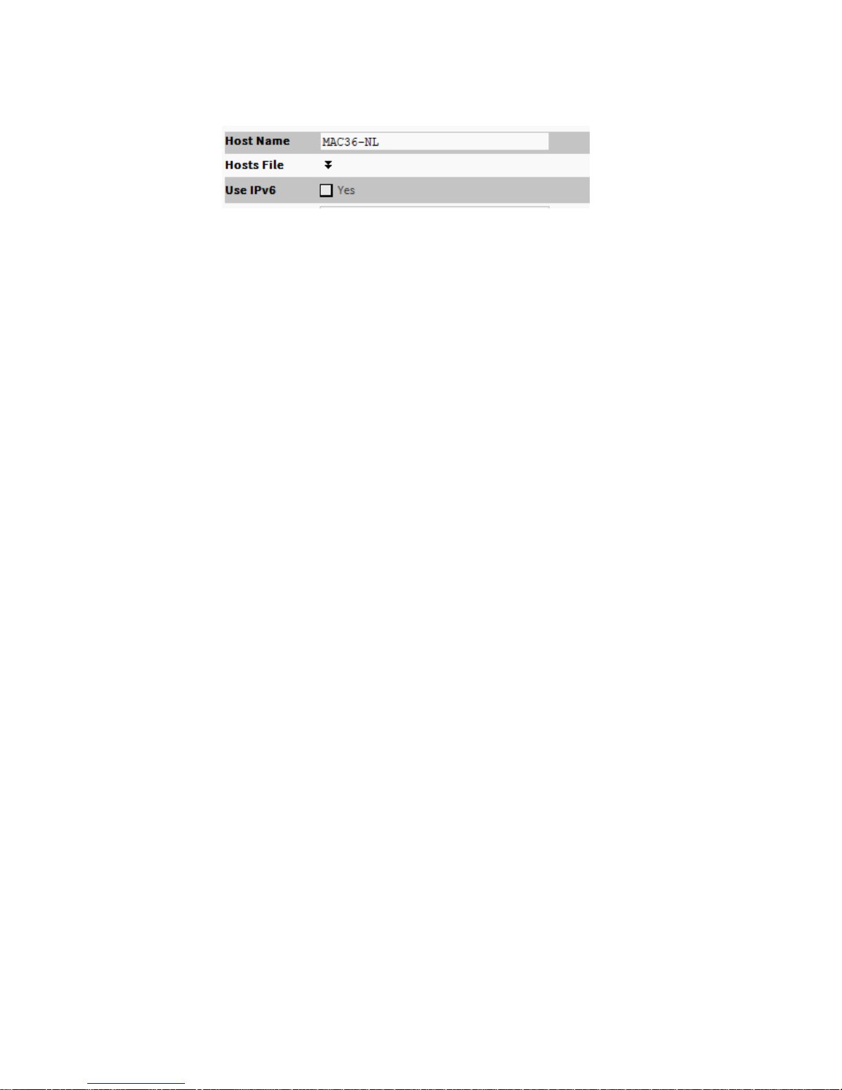
The top of the TCP/IP Configuration view provides the platform’s TCP/IP host settings.
These available host fields are as follows:
Host Name
Synonymous with “computer name,” this is a string that can be processed by a DNS server to
resolve to an IP address. On Windows-based systems, this hostname is the computer’s
identification in its workgroup or domain. If using hostnames, each Niagara platform should
have a unique hostname.
Hosts File
The hosts file is a standard TCP/IP hosts file, where each line associates a specific IP address
with a known host name. To review, click the expand control to see all entries.
For the iSMA-B-MAC36NL controller, you can edit its host file.
To add an entry, click at the end of the last line and press Enter.
Then type the IP address, at least one space, then enter a known host name.
To delete an entry, drag to highlight the entire line, then press Backspace.
Click the expand control again to collapse the Hosts File editor.
Use IPv6
Default is No (unchecked). If set to Yes (checked), Niagara (platform daemon and station)
responds to IPv6 requests, that is, creates IPv6 server sockets (daemon) and IPv6 fox
multicast sockets.
Page 33
iSMA-B-MAC36NL
Version 1.0 www.gc5.pl Page 33 / 40
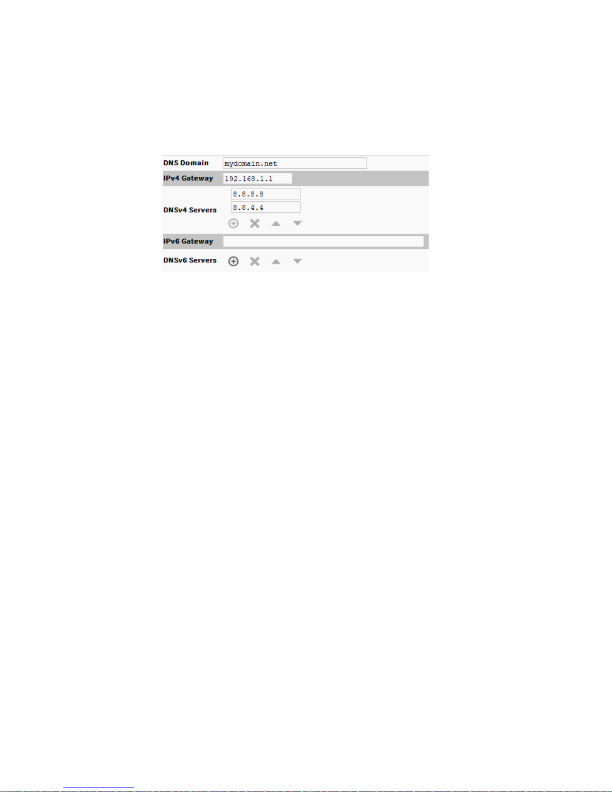
If connected to the iSMA-B-MAC36NL controller, the DNS and gateway settings are also “host-
level” parameters in the TCP/IP Configuration view, as shown below.
* For a Windows-based host, DNS and gateway settings are available under each Interface
section.
The available fields for iSMA-B-MAC36NL controllers are as follows:
DNS Domain
The TCP/IP Domain Name System (DNS) domain this host belongs to, if used.
IPv4 Gateway
The IP address of the router that forwards packets to other IPv4 networks or subnets. A valid
gateway address is required in multi-station (MAC36) jobs to allow point discoveries under
Niagara Networks.
DNSv4 Servers
The IP address of one or more DNS servers (if available), where each can automate
associations between hostnames and IPv4 addresses. Included are icon-buttons to Add (
enter IP address of server), Delete and move Up/Down (set the DNS search order).
IPv6 Gateway
The IPv6 address for the router that forwards packets to other IPv6 networks or subnets.
DNSv6 Servers
The IPv6 address for one or more IPv6 DNS servers (if available), where each can automate
associations between hostnames and IPv6 addresses. Included are icon-buttons to Add (enter
IP address of server), Delete and move Up/Down (set the DNS search order).
Page 34
iSMA-B-MAC36NL
Version 1.0 www.gc5.pl Page 34 / 40
To save yourself some time when making multiple changes, enter all changes before you
continue.
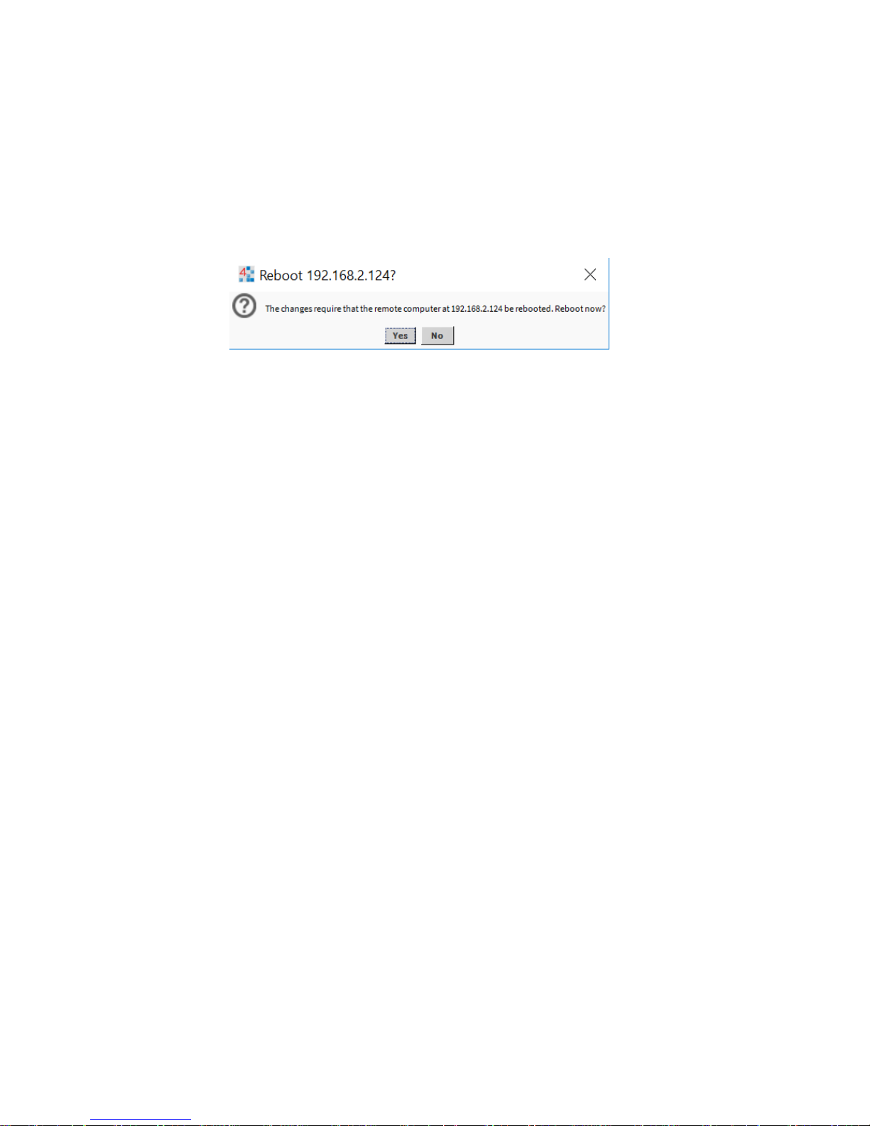
When you finish the configuration, click Save.
The system displays:
Reboot the controller for the changes to take effect.
Page 35
iSMA-B-MAC36NL
Version 1.0 www.gc5.pl Page 35 / 40
3.6 Connection to the console
If a more complex troubleshooting, analysis or changes of the iSMA-B-MAC36NL controller
are required, console mode could be used. Console mode is often used to connect to the
controller with unknown Network Settings. To put the controller into the debug system
console mode, plug-in the USB-to-MiniUSB cable. This makes the system console available at
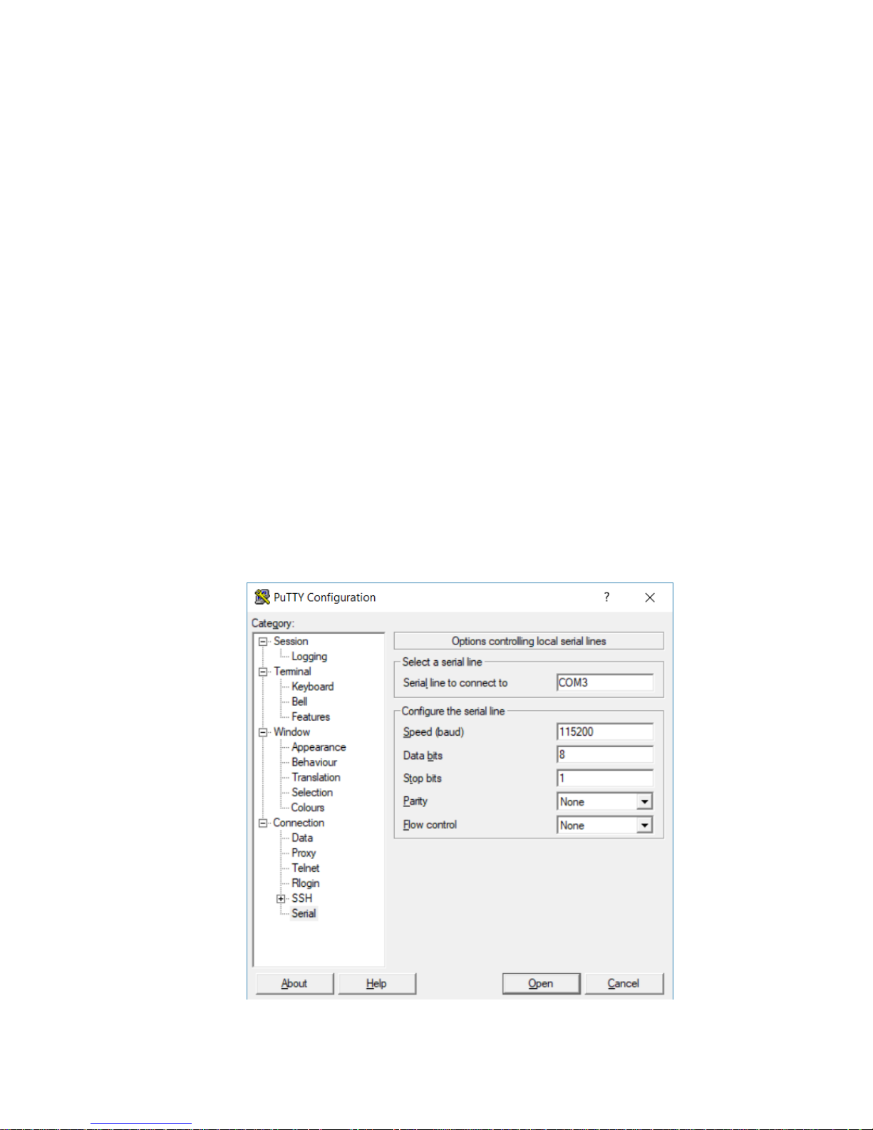
the debug port, at a predefined serial rate: 115200, 8, N, 1. After connection it is possible to
login with platform credentials.
More detailed instruction is described below:
1. Connect to controller’s debug port using the USB cable.
2. Start terminal emulation software on your PC. We recommend PuTTY, which can be
downloaded from https://www.chiark.greenend.org.uk/~sgtatham/putty/latest.html
3. In the category tree expand “Connection” branch and choose “Serial”.
4. Set the “Serial line to connect to” USB COM port, in which the controller has been detected.
It is possible to check which port is in use in Windows Device Manager.
5. Set the “Configure the serial line” fields as shown in the figure below
Figure 19 COM port settings in PuTTY
Page 36
iSMA-B-MAC36NL
Version 1.0 www.gc5.pl Page 36 / 40
6. In the category tree click “Session” and choose “Connection type” as a “Serial”.
7. Click “Open” button at the bottom of the PuTTY window.
8. Enter a platform user name and password (factory platform user: tridium, password:
niagara)
3.7 Controller system update
Preparations for updating
If the GC5 releases an update of one or more components of the controller system (OS, NEL,
JVM), we can perform its remote update using a distribution files without the need for physical
access to the SD card.
After downloading the update from the GC5's support website, the zip file should be unpacked.
You will receive two files - the first is a configuration file (file nre-config-iSMA-iSMA-B-
MAC36NL.dist), the second file containing the appropriate updated system component. Both
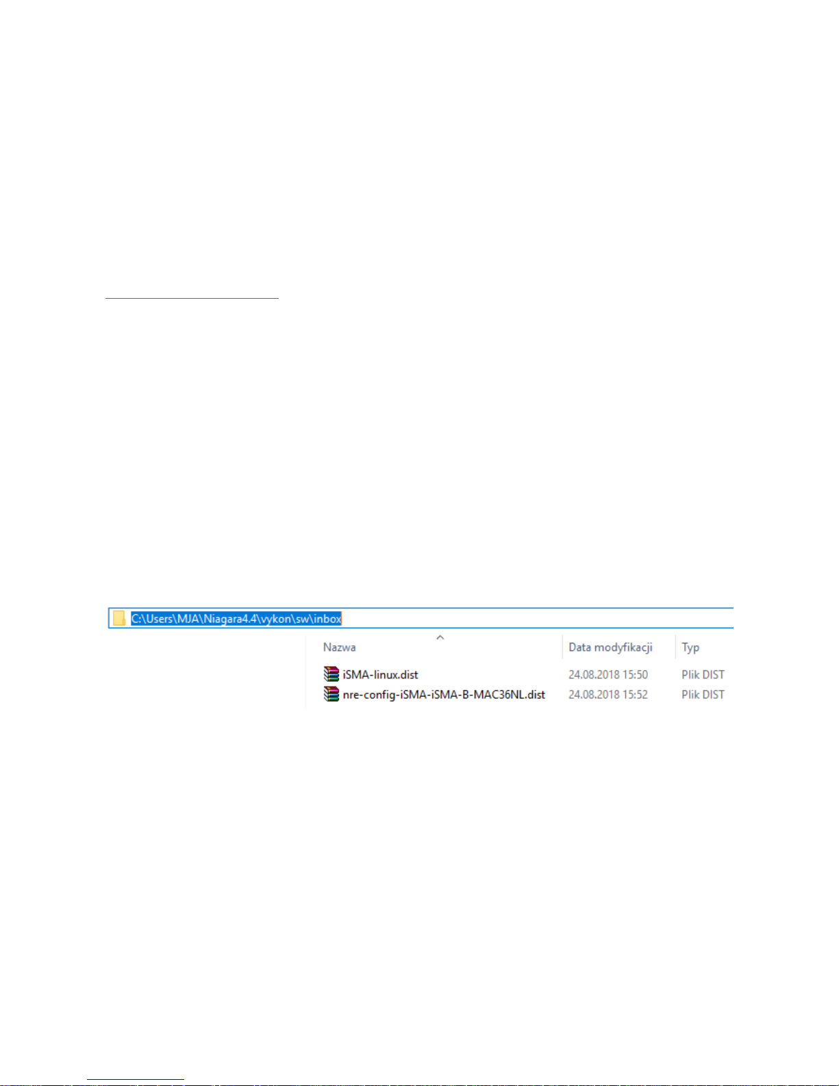
files should be copied to the directory C:\Users\(User folder)\Niagara4.4\vykon\sw\inbox.
Next you must restart the Workplace.
Note: If you are using Niagara version 4.4.73.24 you need to upgrade the module platDeamon-
se.jar from the GC5’s support website.
Figure 20 Folder for update files
Note: It is necessary to update the individual components of the controller system separately,
including copying files (for each update there is a proper configuration file - with the same
name but with different content).
The files will be copied to the appropriate folders with the version numbers under the C:\
Niagara\Niagara-4.4.73.24\sw folder during the Commissioning Wizard process or after
launching from the Platform a Distribution File Installer process.
Page 37
iSMA-B-MAC36NL
Version 1.0 www.gc5.pl Page 37 / 40
Installing the update
After logging into the Platform of the controller, click the right mouse button on the Platform
and run the Commissioning Wizard process
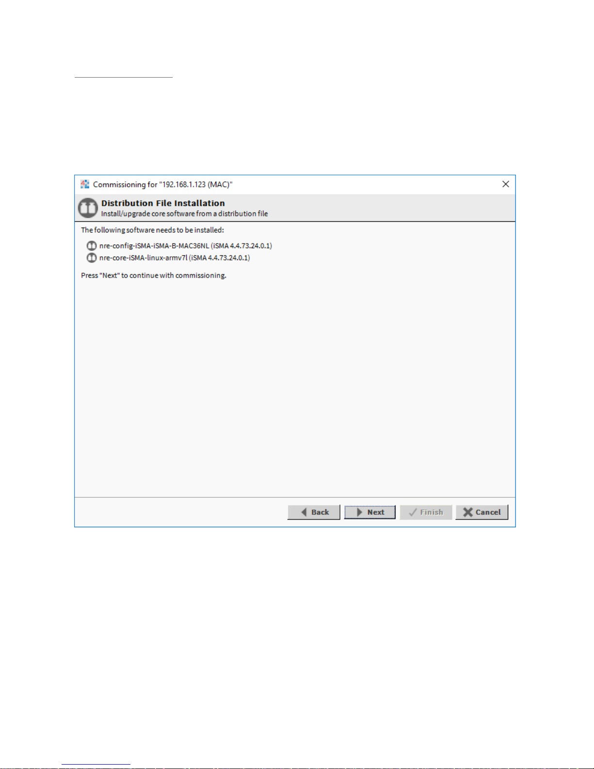
Passing through the next wizard windows, an additional window will appear informing you
about the need to update the appropriate controller system component (OS, NEL, JVM).
Figure 21 Commissioning Wizard with tab informing about the needs to update
Note: No additional window in the Commissioning Wizard means that the controller has the
current version of the system component and there is no need to be update - you can cancel
the Commissioning Wizard process.
Go to the last window of wizard and click on the Finish button. And there is an automatic
update of the controller system component.
After the update is completed, the controller is rebooted. After the reboot, we have the latest
available version of controller’s system component.
Page 38

iSMA-B-MAC36NL
Version 1.0 www.gc5.pl Page 38 / 40
Current version numbers of the controller’s system component can be checked in the Platform
/ Platform Administration.
Page 39
iSMA-B-MAC36NL
Version 1.0 www.gc5.pl Page 39 / 40
3.8 Restore controller to the default state
At times it may be necessary to restore an controller to a known good empty state, either to
recommission it with the current release build, or before recommissioning it with an earlier
build. To do this, you can install a clean dist (distribution) file.
After downloading the clean dist from the manufacturer's website, the file should be copied to
the directory C:\Niagara\Niagara-4.4.73.24\cleanDist. Next you must restart the Workplace.
Note: Installing a clean dist wipes the entire file system and installs an appropriate version of
Niagara platform daemon, resetting the unit to a near factory state. All other data is deleted
from the file system, including station bog files, Px files, modules, etc. The unit’s TLS private
key information is also deleted. In addition, installing a clean dist deletes all configured
platform users, restoring the factory-default platform credentials and port (3011). Only TCP/IP
settings, license file and secure communication configuration (TLS) will be preserved.
To perform the restore to the default state, open a Platform connection to the controller. To
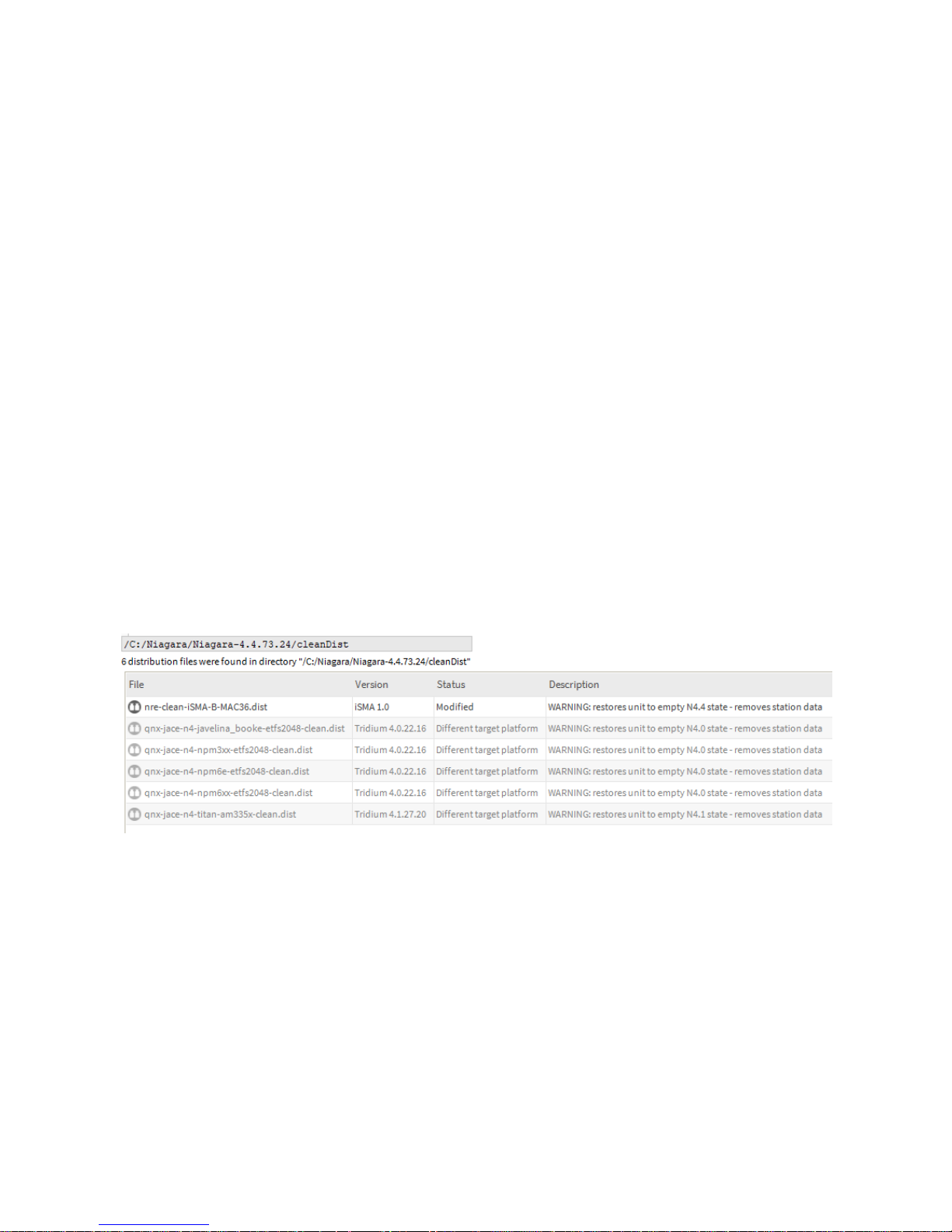
access the cleanDist directory, open the Distribution File Installer and click the Cleaning
button. Each clean dist file has the suffix -clean in its name. Clean distribution files are located
in C:\Niagara\Niagara-4.4.73.24\cleanDist folder.
Figure 22 Distribution File list with Clean Dist files
Next select the appropriate clean dist file for the platform and click Install. Removing a file
system takes a few minutes, then the controller automatically reboots. Wait for the reboot to
complete.
Note: After reboot from a clean dist install, the controller requires port (3011).
Page 40

iSMA-B-MAC36NL
Version 1.0 www.gc5.pl Page 40 / 40
After that you must re-install the software versions to the controller, open a version of
Workbench that uses the same software version (N4.4) that you want on the controller, and
use the Platform \ Commissioning Wizard to install the desired software build.
 Loading...