

Page 1
iSMA-B-FCU
User Manual
FCU Hardware
Global Control 5 Sp. z o.o.
Warsaw, Poland
www.gc5.pl
Page 2

iSMA-B-FCU /FCU Hardware
Version 1.1 www.gc5.pl Page 2 / 37
Table of contents
1 Introduction 3
1.1 Document change log 3
1.2 Safety rules 3
1.3 Technical specifications 4
1.4 Dimensions 6
2 Hardware specification 7
2.1 Diagram of terminals and internal connections 7
iSMA-B-FCU-HH 7
iSMA-B-FCU-HL 8
iSMA-B-FCU-LL 9
2.2 Power supply connection 10
24V AC power supply for external equipment 10
2.3 Connecting the communication bus (RS485) 11
RS485 grounding and shielding 11
RS485 network termination 11
2.4 RJ12 Panel connection 12
2.5 Mini USB Port 12
2.6 Front panel LED functions 12
2.7 Setting controller address 13
2.8 Baud rate selection 14
2.9 Protocol selection 15
2.10 Restoring the default settings 15
2.11 Default settings 15
2.12 CFG DIP switch 16
3 ISMA-B-FCU device inputs 17
3.1 Special Inputs 17
Special Inputs operating as digital inputs 17
Special Inputs operating as 0-10 V DC analog inputs 18
Special Inputs operating as resistance inputs 18
Special Inputs operating as temperature inputs 19
3.2 Digital Inputs 20
Digital Input fast counter 20
4 ISMA-B-FCU device outputs 21
4.1 Triac Outputs 21
4.2 Digital Outputs 22
O1 – O3 relays “Fan” 22
O4 – HTG relay “Electrical Heater” 22
O5 – CLG relay “Electrical Cooler” 23
4.3 Analog Outputs 24
5 MAC DIP SWITCH addressing table 26
6 List of supported temperature sensors 32
Page 3

iSMA-B-FCU /FCU Hardware
Version 1.1 www.gc5.pl Page 3 / 37
1 Introduction
This document presents ISMA-B-FCU device hardware information.
1.1 Document change log
V1.1 – iSMA-B-FCU-LL hardware description added
1.2 Safety rules
• Please note: incorrect wiring of this product can cause its’ damage and may result in other
hazards. Make sure the product has been correctly wired before turning the power ON.
• Before wiring, or removing / mounting the product, be sure to turn the power OFF. Failure to
do so might cause electric shock.
• Do not touch electrically charged parts such as the power terminals. Doing so might cause
electric shock.
• Do not disassemble the product. Doing so might cause electric shock or faulty operation.
• Use the product within the operating ranges recommended in the specification (temperature,
humidity, voltage, shock, mounting direction, atmosphere etc.). Failure to do so might cause
fire or faulty operation.
• Tighten the wires firmly to the terminal. Insufficient tightening of the wires to the terminal
might cause fire.
Page 4

iSMA-B-FCU /FCU Hardware
Version 1.1 www.gc5.pl Page 4 / 37
1.3 Technical specifications
iSMA-B-FCU-HH
iSMA-B-FCU-HL
iSMA-B-FCU-LL
Power supply
Voltage
230V AC ± 10%
24V AC ± 10%
Power consumption
Max 12VA (Including 7 VA for Triac outputs)
Special Inputs
Temperature input
Measurement with attached RTDs
resolution ±0.1°C
accuracy ±0.2°C at 25°C
Voltage input
Voltage measurement from 0 to 10 VDC
(Input impedance 120 KΩ)
resolution ±6 mV
accuracy ±50 mV
Resistance input
Resistance measurement from 0 to 700 kΩ
Measurement resolution ±20 Ω for 20 kΩ load
Dry contact input
Output current ~0.2 mA
Measurement resolution
12 bits
Digital Inputs
Type
Dry contact
Max input frequency
100Hz
Analog Outputs
Voltage range
0 to 10 V DC
Max. load current
5 mA
Resolution
12 bits
Accuracy
±1%
Digital Outputs
(relays)
Resistive load
(FAN, CTG)
6A at 230V AC or 6A at 30V DC
Inductive load AC3
(FAN, CTG)
75VA at 230 V AC or 10 W at 30 V DC
Resistive load (HTG)
10A at 230V AC or 10 A at 30 V DC
Inductive load AC3
(HTG)
1/2 HP at 230 V AC
Triac Outputs
Load
Min: 20 mA
Max: 0.5 A at
230 V AC
Min: 20 mA
Max: 0.3 A at
24 V AC
I
max
= 0.3 A =
I
TO1
+ I
TO2
+ I
24VOut
Min: 20 mA
Max: 0.5 A at 24 V
AC
Peak load per channel
1.5 A (30 s)
Gate Control
Zero crossing turn ON
Frequency Range
47 to 63 Hz
Snubber
Snubberless Triac
Power Supply
output
Power Supply output
24 V AC ± 20%,
7 VA
24 V AC ± 20%, 7 VA*
* In HL this Power Supply is also
used for Triac Outputs
RS485
RS485
Up to 128 devices
Page 5

iSMA-B-FCU /FCU Hardware
Version 1.1 www.gc5.pl Page 5 / 37
Interface
Failsafe Receiver (Bus Open, Bus Shorted, Bus Idle)
Communication
protocols
Modbus RTU, Modbus ASCII or BACnet MSTP
set by switch
Baud rate
From 2400 to 115200 set by switch
Address
0 to 255 set by DIP switch
RJ12 Interface
RS485
Up to 128 devices
Communication
protocol
Modbus RTU
Baud rate
From 2400 to 115200
Power supply
34 V DC ± 15%, 2.5 W
USB
USB
Mini USB 2.0
Ingress
protection
IP
IP40
Temperature
Storage
– 40°C to +85°C
Operating
0°C to +50°C
Humidity
Relative
5 to 95%
Connectors
Inputs / Outputs,
Power Supply and
Communication
Removable
HTG Relay
Constant
Maximum cable size
1.5 mm2
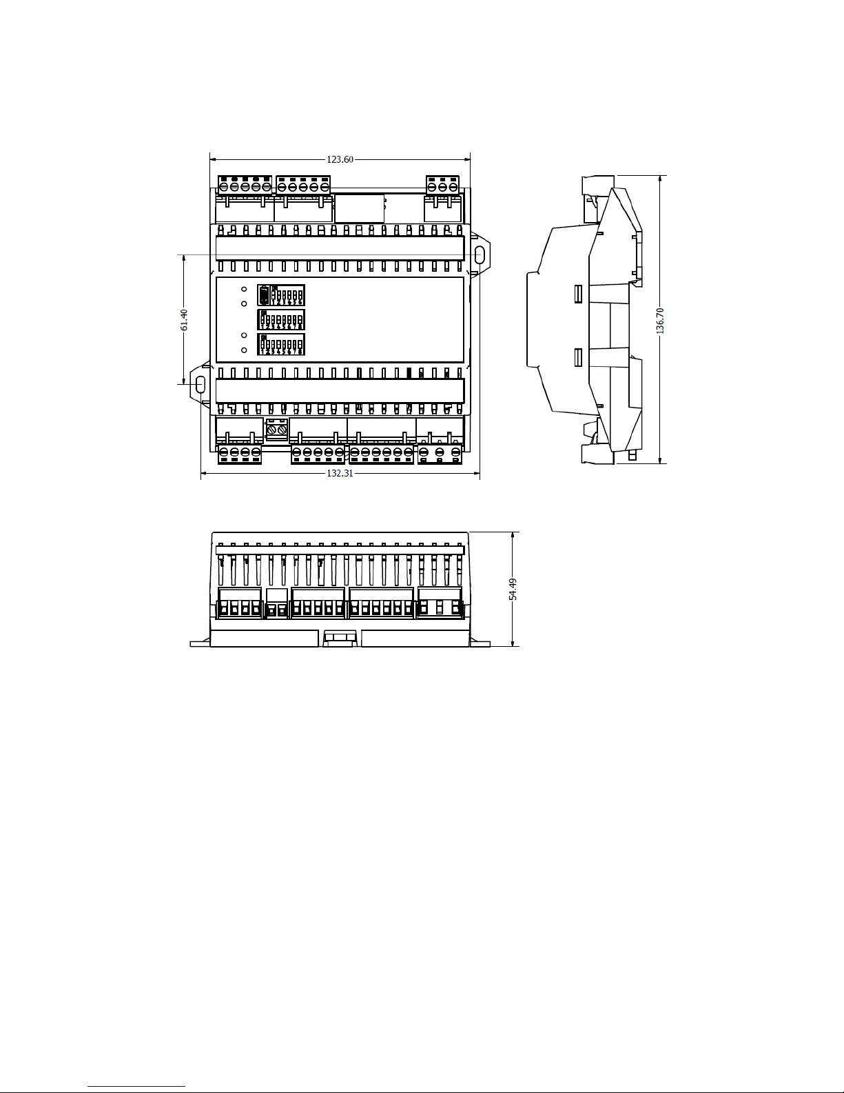
Dimensions
Width
123 mm
Length
137 mm
Height
55 mm
Table 1 Technical specification
Page 6
iSMA-B-FCU /FCU Hardware
Version 1.1 www.gc5.pl Page 6 / 37
1.4 Dimensions
Figure 1 iSMA-B-FCU dimensions (all versions)
Page 7
iSMA-B-FCU /FCU Hardware
Version 1.1 www.gc5.pl Page 7 / 37
2 Hardware specification
2.1 Terminals and internal connection diagram
There are 3 types of hardware available:
• iSMA-B-FCU-HH with 230 V AC power supply and Triac Outputs,
• iSMA-B-FCU-HL with 230 V AC power supply and 24 V AC Triac Outputs,
• iSMA-B-FCU-LL with 24 V AC power supply and Triac Outputs.
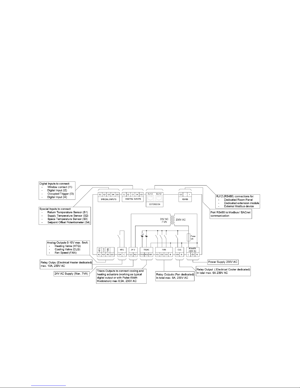
2.1.1 iSMA-B-FCU-HH
iSMA-B-FCU-HH has a high voltage power supply (230 V AC) and high voltage Triac Outputs
(230 V AC). The Triac Outputs are connected directly to the main controller power supply as
presented in diagram below. The maximum current for each Triac Output is 0.5 A. The maximum
power consumed by external equipment connected to the
24 V terminals (L2, N2) cannot exceed 7VA in total.
Figure 2 iSMA-B-FCU-HH diagram of terminals and internal connections
Page 8
iSMA-B-FCU /FCU Hardware
Version 1.1 www.gc5.pl Page 8 / 37
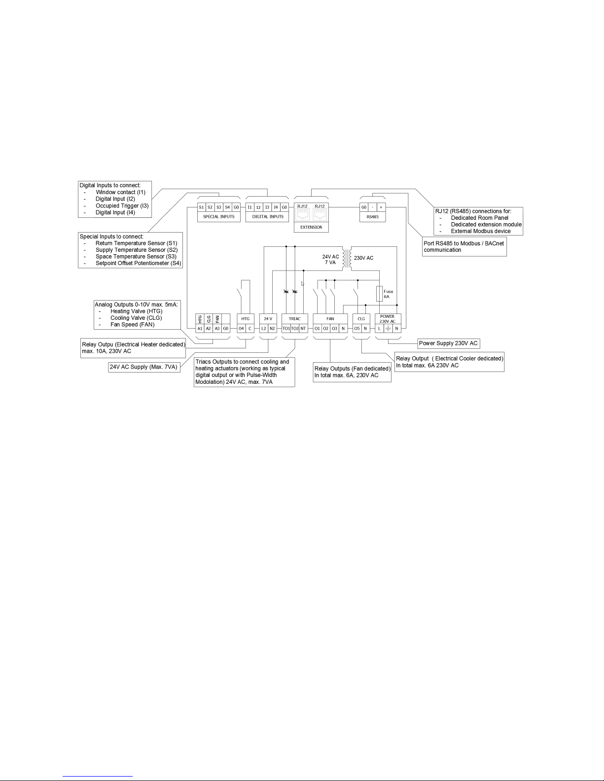
2.1.2 iSMA-B-FCU-HL
iSMA-B-FCU-HL has a high voltage power supply (230 V AC) and low voltage Triac Outputs (24 V
AC). The Triac Outputs are connected to a built-in 24 V AC transformer as shown in the below
diagram. The maximum power consumed by the external equipment connected to the Triac
Outputs and to 24 V terminals (L2, N2) cannot exceed 7 VA in total.
Figure 3 iSMA-B-FCU-HL diagram of terminals and internal connections
Page 9

iSMA-B-FCU /FCU Hardware
Version 1.1 www.gc5.pl Page 9 / 37
2.1.3 iSMA-B-FCU-LL
iSMA-B-FCU-LL has a low voltage power supply and Triac Outputs (24 V AC). The Triac Outputs are
connected to power supply terminals. The maximum current for each of the Triac Outputs is 0.5 A.
The maximum power used by external equipment connected to the 24 V terminals (L2, N2) cannot
exceed 7 VA in total.
Figure 4 iSAM-B-FCU-LL diagram of terminals and internal connections
Page 10
iSMA-B-FCU /FCU Hardware
Version 1.1 www.gc5.pl Page 10 / 37
2.2 Power supply connection
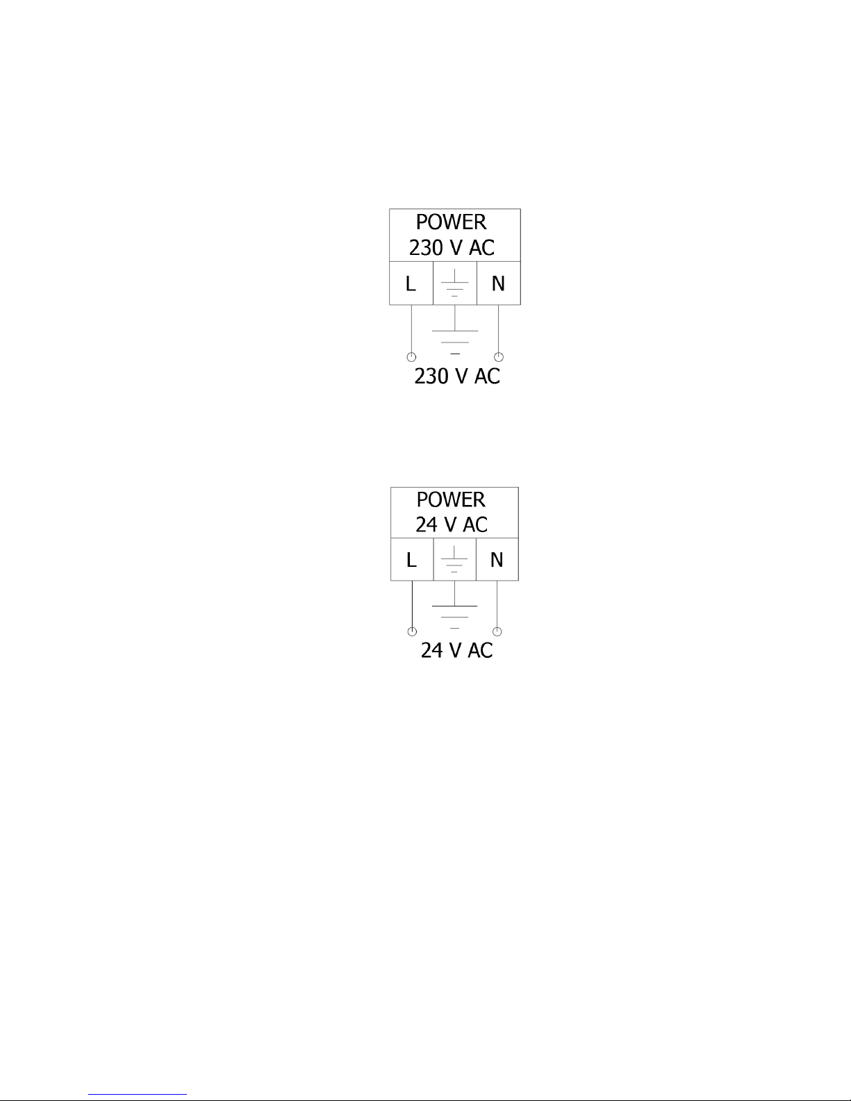
iSMA-B-FCU-HH and iSMA-B-FCU-HL are designed to work with 230 V AC power supply. Each ISMAB-FCU device is equipped with a built-in 6 A fuse protecting the controller and connected 230 V AC
equipment.
Figure 5 230 V AC Power supply connection
iSMA-B-FCU-LL is designed to work with 24 V AC power supply. The device is equipped with a builtin 6 A fuse protecting the controller and connected 24 V AC equipment.
Figure 6 24 V AC Power supply connection
Note: Total current for digital relay outputs O1-O4 cannot exceed 6A.
Note: It is forbidden to use a fuse with current exceeding 6 A! Higher current may permanently
damage the device and cause danger to the user and to the equipment!
2.2.1. 24 V AC power supply for external equipment
iSMA-B-FCU-HH is equipped with a 24 V AC, 7 VA power supply output to supply an external
equipment like sensors and actuators. This power supply uses a separate coil in the transformer.
24 V AC power supply terminal connection is labeled L2, N2.
iSMA-B-FCU-HL is equipped with a 24 V AC power supply output for thermal valves controlled by
Triac Outputs and external devices like sensors and actuators. This power supply uses a separate
coil in the transformer. 24 V AC power supply terminal connection is labeled L2, N2. The total power
Page 11
iSMA-B-FCU /FCU Hardware
Version 1.1 www.gc5.pl Page 11 / 37
consumption with thermal valves and external devices cannot exceed 7 VA (~0.3 A).
iSMA-B-FCU-LL is equipped with a 24 V AC, 7 VA power supply output to supply the external
equipment like sensors and actuators. This power supply uses a separate 24 V AC transformer.
The external separate power supply terminal connection is labeled L2, N2.
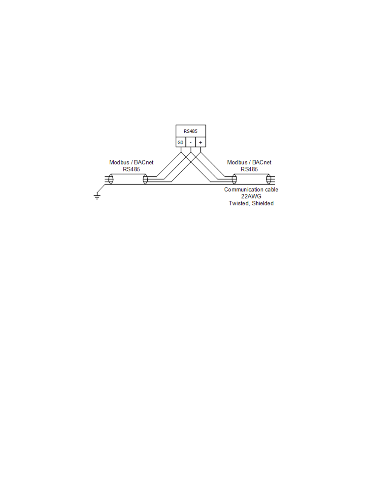
2.3 Connecting the communication bus (RS485)
Figure 7 RS485 connection
2.3.1 RS485 grounding and shielding
This device can be exposed to electromagnetic field. Electromagnetic radiation can induce
electrical noise into both power and signal lines, as well as direct radiation into the FCU device with
negative results for the system. Appropriate grounding, shielding and other protective steps should
be taken at the stage of installation to prevent these effects. These protective steps include
grounding the control cabinet and the cable shield, installing protective elements for
electromagnetic switching devices, correct wiring, as well as proper choice of cable types and their
cross sections.
2.3.2 RS 485 network termination
Transmission line effects often present a problem for data communication networks. These
problems include reflections and signal attenuation.
To eliminate the presence of reflections of signal from the end of the cable, the cable must be
terminated at both ends with a resistor across the line adequate to its characteristic impedance.
Both ends must be terminated since propagation is bidirectional. In case of an RS485 twisted
pair cable this termination is typically 120 Ω.
Page 12
iSMA-B-FCU /FCU Hardware
Version 1.1 www.gc5.pl Page 12 / 37
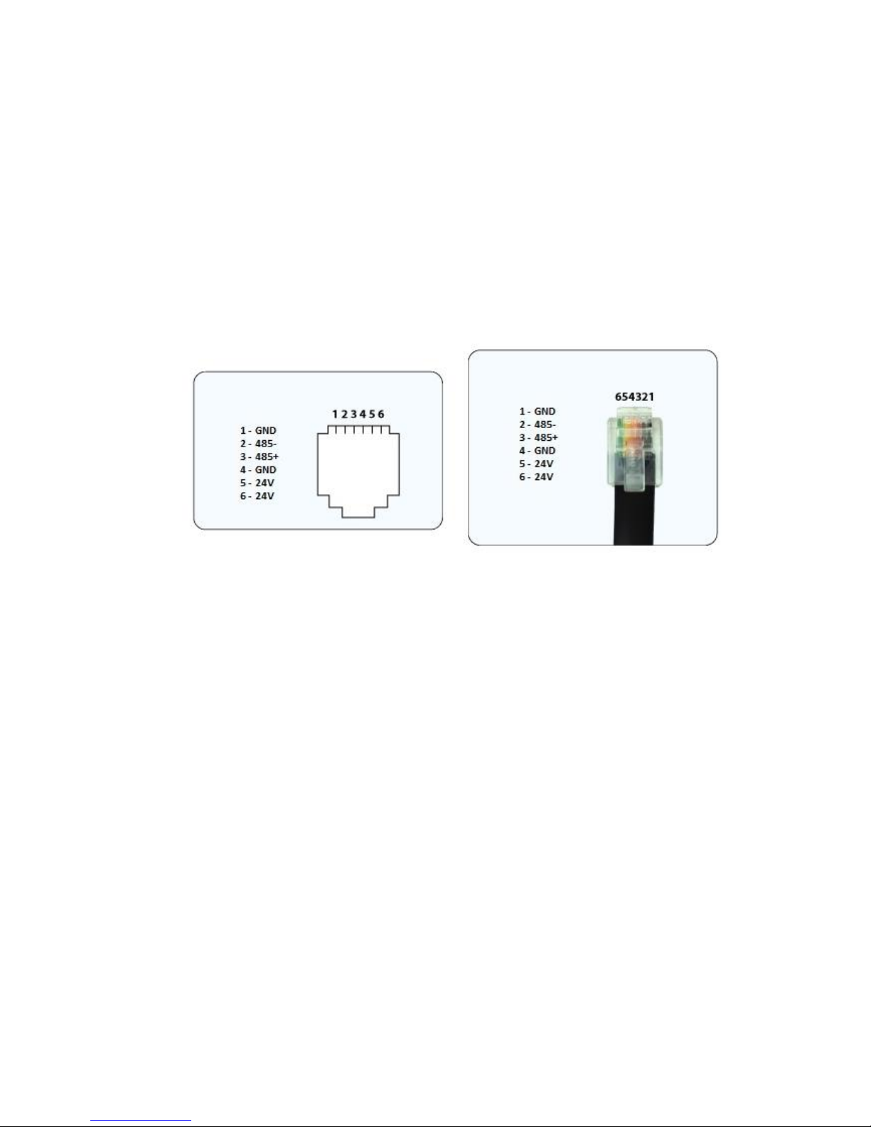
2.4 RJ12 Panel connection
RJ12 socket is designed for connecting external modules and LCD panel. The ISMA-B-FCU
device has two parallel sockets with the same pin configuration. Those sockets provide
communication in Modbus RTU protocol.
RJ12 socket provides also power supply dedicated for external LCD panels with maximum load
up to 2.5 W. Before connecting devices powered from RJ12 please calculate the power supply
load. Power consumption of the dedicated wall panel iSMA-B-LP with temperature sensor is 0.5
W, so the maximum number of panels on the bus is 5.
RJ12 pins are shown in the figure below.
Figure 8 RJ12 pin description
For short distance, up to 100 m, it is recommended to use the following cables for connection:
standard category 3, 4 wire or 6 wire telephone cable straight without crossing (for example
YTLYP 6x0.12). For longer distance, it is recommended to use twisted shielded Modbus standard
cable.
2.5 Mini USB Port
The iSMA-B-FCU device has a built-in mini USB port designed to manage controller firmware and
application, as well as for diagnostics.
This USB port also provides controller power supply for commissioning processes and for
application diagnostics. When the controller is powered up by a USB, all inputs and outputs are
operational (except for Triac Outputs which require external power supply).
2.6 Front panel LED functions
The ISMA-B-FCU device is equipped with 4 LED diodes for quick status check and diagnostics:
• Power LED lights up (green) after turning the power on.
• Communication LED lights up (orange) for 20 ms after sending each package through the main
RS485 port. As long as module receives/sends packages, the Communication LED blinks
continuously.
Page 13

iSMA-B-FCU /FCU Hardware
Version 1.1 www.gc5.pl Page 13 / 37
• Extension Communication LED lights up (orange) for 20 ms after sending each package
through the extension ports. As long as the module receives / sends packages, the Extension
Communication LED blinks continuously.
• User LED is OFF as default, the function is programmable through LED_ALARM component; it
blinks very softly when there is a fault during the start-up of Sedona virtual machine.
• During device reset, when Switch 6 in DIP switch PROTOCOL is in ON position (default settings
restoration mode), Power LED blinks in 300 ms time intervals. After Switch 6 is switched OFF,
Power LED is lit permanently and the default settings are restored.
• When the device remains in bootloader status, the Power LED and the Communication LED blink
alternatively. The communication LED keeps its functionality and blinks also after
sending/receiving data packages.
2.7 Setting Controller Address
The Controller Address is a setting made with a Dip switch MAC. The procedure of setting the
address in presented in the figure and table below. The addressing table is shown at the end of
this document.
Figure 9 MAC Dip Switch
Number of
Dip Switch
MAC
Position
Function
1
On
Add 1 to MAC Address
Off
Add 0 to MAC Address
2
On
Add 2 to MAC Address
Off
Add 0 to MAC Address
3
On
Add 4 to MAC Address
Off
Add 0 to MAC Address
4
On
Add 8 to MAC Address
Off
Add 0 to MAC Address
5
On
Add 16 to MAC Address
Off
Add 0 to MAC Address
6
On
Add 32 to MAC Address
Off
Add 0 to MAC Address
7
On
Add 64 to MAC Address
Page 14
iSMA-B-FCU /FCU Hardware
Version 1.1 www.gc5.pl Page 14 / 37
Off
Add 0 to MAC Address
8
On
Add 128 to MAC Address
Off
Add 0 to MAC Address
Table 1 Setting MAC address with a Dip Switch
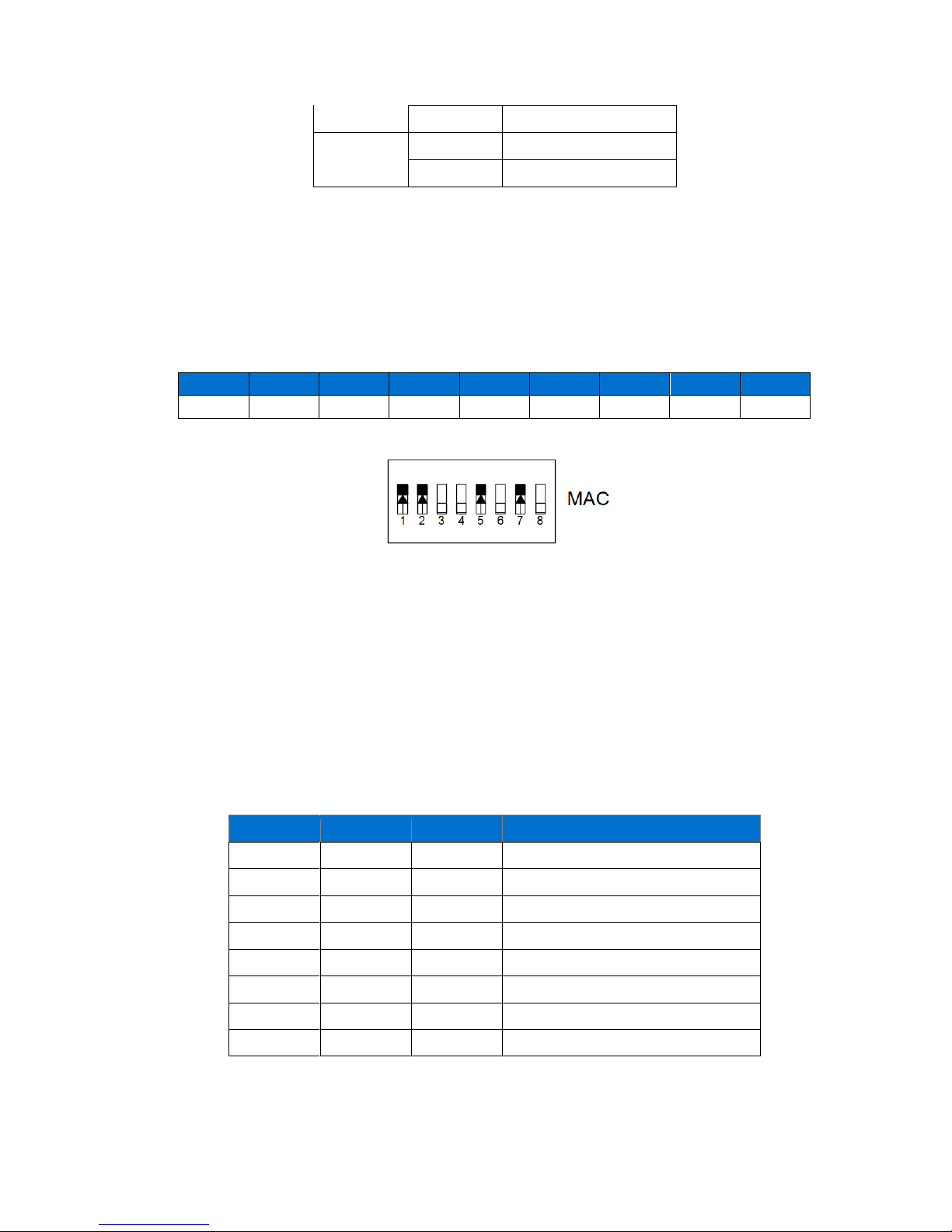
Example: Configuration setting of the ISMA-B-FCU device address 83.
Address 83 contains following multiplicity of number 2: 83 = 1 + 2 + 16 + 64. Address DIP switch
settings are presented in the table below. All addresses of DIP switch configuration are presented
in the table at the end of this document.
Address
S1
S2
S3
S4
S5
S6
S7
S8
83
On
On
On On
Table 2 Address 83 DIP switch configuration
Figure 10 MAC DIP switch address 83 settings
WARNING! In BACnet network setting, the address above 128 automatically switches BACnet to
Slave mode. In this mode, the device cannot be discovered in device searching process.
WARNING! Do not set address 255 (all switches in ON position). This address setting is reserved
for system operation.
2.8 Baud rate selection
Transmission baud rate is determined by S3 switch (sections 1, 2, and 3) in accordance with the
following table:
1 2 3
Baud rate
OFF (0)
OFF (0)
OFF (0)
Defined by the user
OFF (0)
OFF (0)
ON (1)
76800
OFF (0)
ON (1)
OFF (0)
4800
OFF (0)
ON (1)
ON (1)
9600
ON (1)
OFF (0)
OFF (0)
19200
ON (1)
OFF (0)
ON (1)
38400
ON (1)
ON (1)
OFF (0)
57600
ON (1)
ON (1)
ON (1)
115200
Table 2 Baud rate selection
Page 15

iSMA-B-FCU /FCU Hardware
Version 1.1 www.gc5.pl Page 15 / 37
2.9 Protocol selection
Protocol selection is made with sections 4 and 5 of the S3 switch according to the table:
4 5 Protocol
OFF (0)
OFF (0)
Modbus RTU
OFF (0)
ON (1)
Modbus ASCII
ON (1)
OFF (0)
BACnet Master
ON (1)
ON (1)
BACnet Slave
Table 3 Protocol selection
WARNING! In BACnet mode switch number 4 must be on ON(1) position and switch number 5
decides if BACnet works in Master or Slave mode (please check on the above table).
2.10 Restoring the default settings
To restore the default ISMA-B-FCU device settings, follow the steps below:
1. Turn power supply off
2. Set section 6 of Protocol switch to ON
3. Turn on power supply, power LED blinking
4. Switch section 6 of Protocol switch to OFF to restore the default settings. To cancel the reset,
turn off the power and switch section 6 of Protocol switch to the OFF position.
2.11 Default Settings
Out of the box device as well as after restoring default values procedure, has got the following
default settings:
Name
Default Value
USER BAUD RATE
76800
STOP BITS
1
DATA BITS
8
PARITY BITS
0
RESPONSE DELAY
0
I1 – I4 DIGITAL INPUT COUNTERS
0
Table 4 Default values
Page 16

iSMA-B-FCU /FCU Hardware
Version 1.1 www.gc5.pl Page 16 / 37
2.12 CFG DIP switch
The ISMA-B-FCU device has, on the top panel, 8 position DIP switch which can be used in client
application. Each of 8 positions can have true or false state. This DIP switch is dedicated for setting
configuration in client application.
Figure 11 DIP switch CFG
Page 17

iSMA-B-FCU /FCU Hardware
Version 1.1 www.gc5.pl Page 17 / 37
3 ISMA-B-FCU device inputs
ISMA-B-FCU device has two types of inputs: 4 Digital Inputs – for Boolean values, and 4 Special
Inputs – for resistance and voltage measurement.
3.1 Special Inputs
ISMA-B-FCU device has 4 built-in special inputs which can work in the following modes:
• Digital Input – dry contact,
• Analog Input - 0-10 V DC,
• Resistance Input- 0 – 1000 kΩ (1 MΩ),
• Temperature Input - working with NTC sensors.
3.1.1 Special Inputs working as digital input
In this mode, Special Input works as a digital input dry contact and reactive Boolean value, false
for open circuit and true for close circuit. Circuit status is measured with
1 mA current.
Figure 12 Connection of Special Inputs Dry Contact
Page 18

iSMA-B-FCU /FCU Hardware
Version 1.1 www.gc5.pl Page 18 / 37
3.1.2 Special Inputs working as analog input 0-10 V DC
In this mode, Special Input measures voltage in the range from 0 to 10 V DC (10 000 mV) with 6
mV resolution.
Figure 13 Connection of the Special Inputs voltage sensor
3.1.3 Special Inputs operating as resistance inputs
In this mode, Special Input measures resistance value with voltage driver. The input works in
range from 0 to 1000 kΩ (1 MΩ), with resolution ±20 Ω for 20 kΩ load.
Figure 14 Connection of Special Inputs resistance sensor
Page 19

iSMA-B-FCU /FCU Hardware
Version 1.1 www.gc5.pl Page 19 / 37
3.1.4 Special Inputs working as temperature inputs
In this mode, Special Input measures NTC sensor resistance with voltage driver and converts to
temperature value. Special Input is equipped with a built-in conversion table for the following
NTC sensors:
• 10K3A1 NTC B=3975K temperature sensor
• 10K4A1 NTC B=3695K temperature sensor
• 10K NTC B=3435K Carel temperature sensor
• 20K6A1 NTC B=4262K temperature sensor
• 2.2K3A1 NTC B=3975K temperature sensor
• 3K3A1 NTC B=3975K temperature sensor
• 30K6A1 NTC B=4262K temperature sensor
• SIE1 temperature sensor
• TAC1 temperature sensor
• SAT1 temperature sensor
Figure 15 Connection of Special Inputs NTC sensor
Page 20

iSMA-B-FCU /FCU Hardware
Version 1.1 www.gc5.pl Page 20 / 37
3.2 Digital Inputs
ISMA-B-FCU device is equipped with 4 Digital Inputs. The figure below presents the way they are
connected.
Figure 16 Connection of Digital Inputs Dry Contact
3.2.1 Digital Input fast counter
Digital Input can work as a counter of dry contact impulses up to 100 Hz. Counter value is saved
in non-volatile EEPROM memory.
WARNING! During Restore to Default process, the value of the counter is set to 0.
Page 21

iSMA-B-FCU /FCU Hardware
Version 1.1 www.gc5.pl Page 21 / 37
4 ISMA-B-FCU device outputs
ISMA-B-FCU device is equipped with three types of outputs: 2 Triac Outputs,
5 Digital Outputs, and 4 Analog Outputs.
4.1 Triac Outputs
ISMA-B-FCU device is equipped with two Triac Outputs designed for heating and cooling thermal
valve actuators. Depending on controller model, Triac Outputs can be connected to actuators
with 230 V AC supply (for iSMA-B-FCU-HH) or to actuators with 24 V AC supply (for iSMA-B-FCUHL and iSMA-B-FCU-LL). In iSMA-B-FCU-HL, Triac Outputs are supplied with 24 V AC from a buildin transformer, whereas in iSMA-B-FCU-LL and iSMA-B-FCU-HH Triac Outputs are connected
directly to Power Supply terminals.
Triac Outputs can work as typical binary outputs (for Binary Temperature Control) or with PWM
modulation. PWM mode has two parameters:
• Duration time in seconds (this value depends on valve parameters)
• Fill out (percentage value of signal fill out).
The figure below presents the way actuators are connected to Triac Outputs (for
4 pipes mode).
Figure 17 Connection between Thermal Valves and Triac Outputs: a) iSMA-B-FCU-HH; b) iSMA-B-FCU-HL, and iSMA-B-FCU-LL
WARNING!
In case of iSMA-B-FCU-HH or iSMA-B-FCU-LL controller, the actuators connected to each Triac
Output may consume up to 0.5 A under constant load. In some cases the current can be higher
for a limited time, 1.5 A up to 30 seconds.
In case of iSMA-B-FCU-HL controller, the sum of power consumption of both Triac Outputs and
24 V AC output cannot exceed 0.3 A (7 VA):
I
max
= 0,3 A = I
TO1
+ I
TO2
+ I
24VOut
.
Page 22

iSMA-B-FCU /FCU Hardware
Version 1.1 www.gc5.pl Page 22 / 37
4.2 Digital Outputs
All Digital Outputs are based on relays which can operate with 230 V AC voltage (in iSMA-B-FCULL, Digital Outputs are working with 24 V AC). ISMA-B-FCU device has
2 types of digital outputs:
• O1-03 and 05 – relay outputs connected directly to power supply terminal,
• O4 – a relay separated from ISMA-B-FCU device circuits.
4.2.1 O1 – O3 relays “Fan”
ISMA-B-FCU device is equipped with three relay outputs, designed for connecting up to 3 speed
Fans. The way the Fans are connected (depending on the number of speeds) is presented in the
figure below. The common terminal for those outputs is connected directly to Power Supply “L”
terminal.
WARNING! Outputs O1-O3 and output O5 are protected by a built-in 6 A fuse. Total current for digital
relays outputs O1-03 and O5 cannot exceed 6 A.
WARNING! It is forbidden to use a fuse with current exceeding 6 A! Higher current may permanently
damage device and cause danger to the user and to the equipment!
WARNING! In iSMA-B-FCU-LL, 24 V AC Fan motor is required.
An exemplary fan connection is presented in the figure below.
Figure 18 Digital Outputs O1-O3, example of fan connections
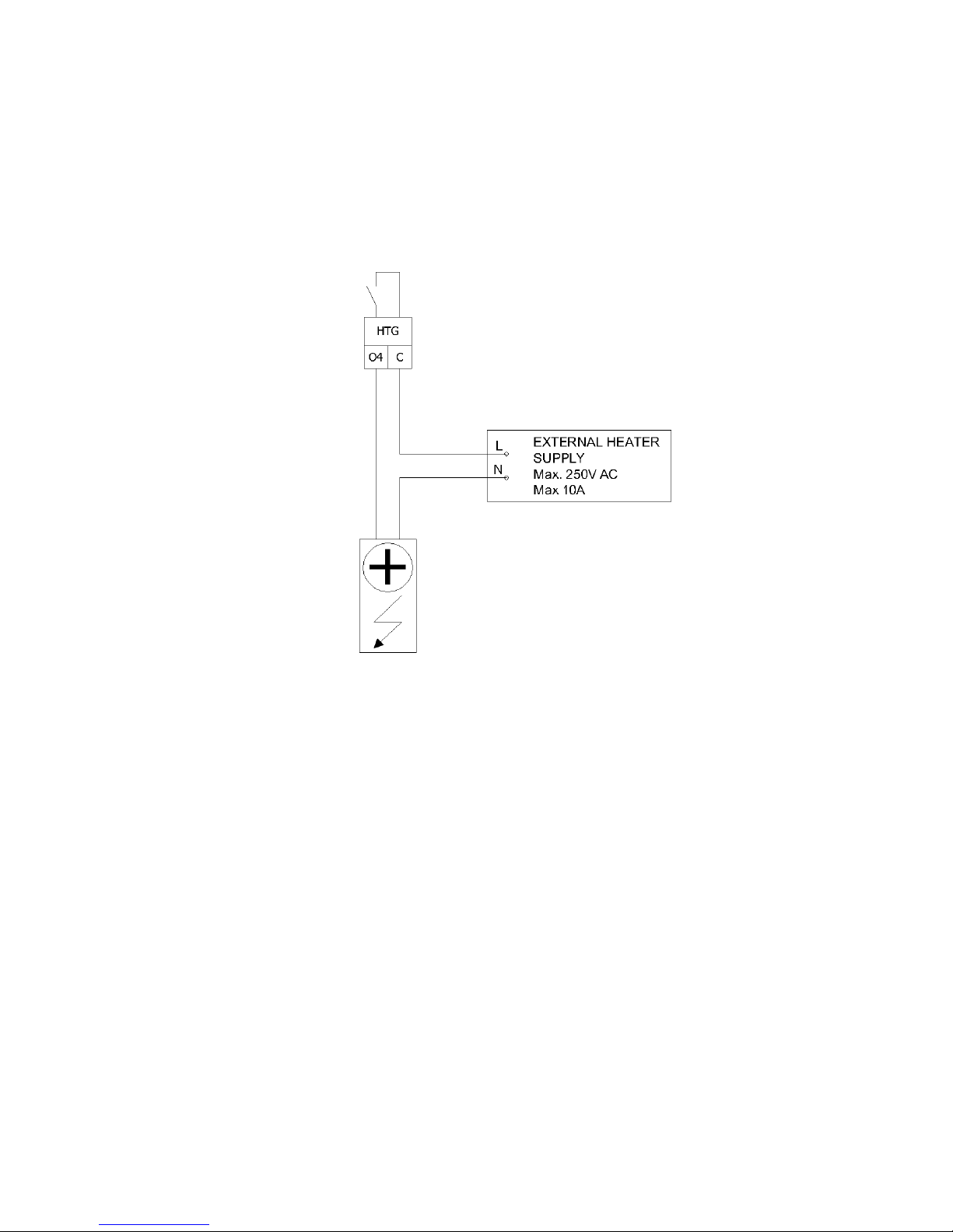
4.2.2 O4 – HTG relay “Electrical Heater”
iSMA-B-FCU device is equipped with relay outputs for connecting for example
an Electrical Heater. This relay is separated from the rest of the control circuit. Current
consumption cannot exceed 10 A with 250 V AC power supply. The figure below presents the
way of connecting.
Page 23
iSMA-B-FCU /FCU Hardware
Version 1.1 www.gc5.pl Page 23 / 37
WARNING! HTG relay voltage is always limited to 250 V AC, irrespectively of the power supply
version of the FCU controller.
WARNING! This digital output is equipped with a separate circuit with 10 A relay. This circuit
requires using external fuse protection up to 10 A. The current higher than 10 A may permanently
damage device and cause danger to the user and to the equipment!
Figure 19 Digital Output O4, exemplary Electrical Heater connection
4.2.3 O5 – CLG relay “Electrical Cooler”
ISMA-B-FCU device is equipped with a relay output, which in FCU application is dedicated to an
external Cooler. This relay output is internally connected to the power supply, therefore there is no
need to connect external supply. In iSMA-B-FCU-HH and iSMA-B-FCU-HL the output voltage in high
state is 230 V AC, and in iSMA-B-FCU-LL version the high state voltage is 24 V AC. Current
consumption cannot exceed 6 A. An exemplary way of connecting is presented in the figure below.
WARNING! Output O4 and outputs O1-O3 are protected by a 6 A fuse. Total current for digital relay
outputs cannot exceed 6A.
WARNING! It is forbidden to use a fuse with current exceeding 6A! Higher current may permanently
damage the device and cause a danger to the user and to the equipment!
Page 24

iSMA-B-FCU /FCU Hardware
Version 1.1 www.gc5.pl Page 24 / 37
Figure 20 Digital Output O5, an example of 230 V AC Electrical Cooler connection (iSMA-B-FCU-HH and iSMA-B-FCU-HL version)
Figure 21 Digital Output O5, an example of 24 V AC Electrical Cooler connection (iSMA-B-FCU-LL version)
4.3 Analog Outputs
ISMA-B-FCU device is equipped with 3 Analog Outputs 0-10 V DC. Those outputs are designed for
controlling the following actuators:
• A1 (HTG) – analog heating valve actuator,
• A2 (CTG) – analog cooling valve actuator,
• A3 (FAN) – analog fan speed control.
Page 25

iSMA-B-FCU /FCU Hardware
Version 1.1 www.gc5.pl Page 25 / 37
The recommended way of connecting the Analog Outputs is presented in the figures below.
Figure 22 Analog Outputs, an exemplary connection of analog 0-10 V valve actuators
Figure 23 Analog Outputs, an exemplary connection of analog 0-10 V fan control
Page 26

iSMA-B-FCU /FCU Hardware
Version 1.1 www.gc5.pl Page 26 / 37
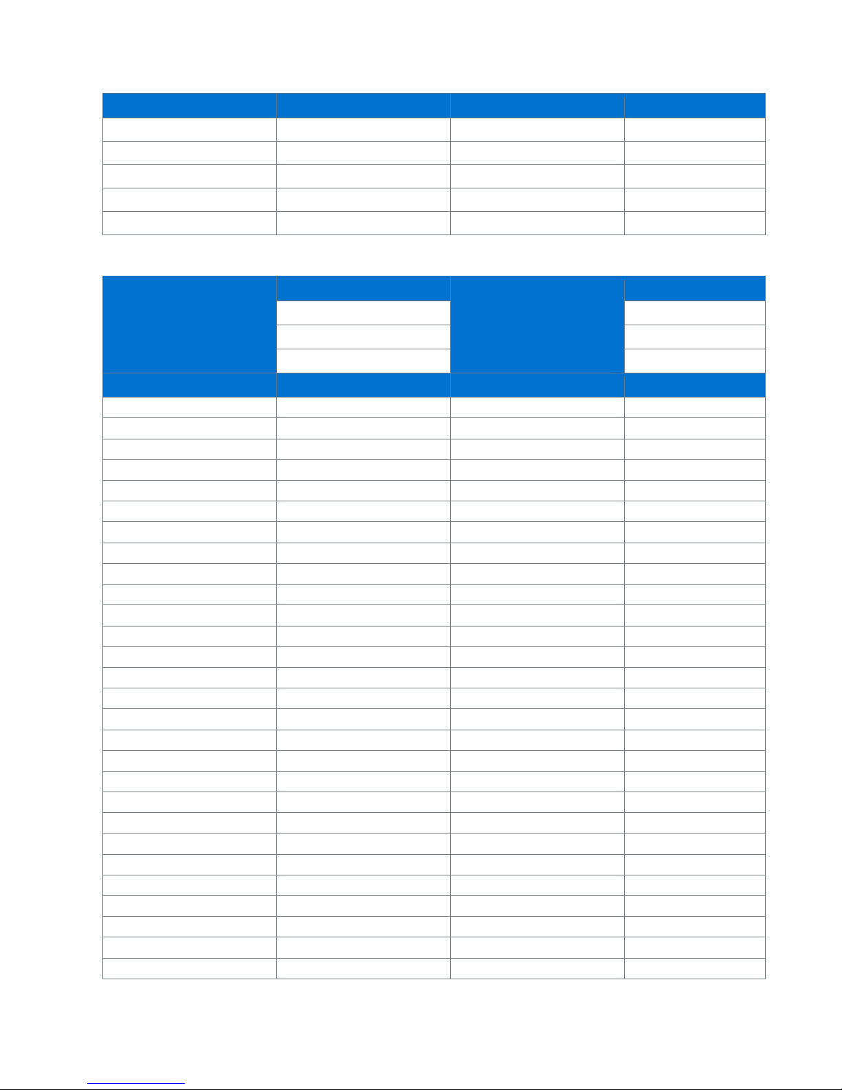
5 MAC DIP SWITCH addressing table
Address
S1
S2
S3
S4
S5
S6
S7
S8
1
On
2 On
3
On
On
4
On
5
On On
6 On
On
7
On
On
On
8
On
9
On
On
10 On On
11
On
On On
12
On
On
13
On On
On
14 On
On
On
15
On
On
On
On
16
On
17
On
On
18 On
On
19
On
On
On
20
On On
21
On On On
22 On
On On
23
On
On
On On
24
On
On
25
On
On
On
26 On On
On
27
On
On On
On
28
On
On
On
29
On On
On
On
30 On
On
On
On
31
On
On
On
On
On
32
On
33
On
On
34 On
On
35
On
On
On
36
On
On
37
On On
On
38 On
On
On
39
On
On
On
On
40
On On
41
On
On On
42 On On On
Page 27

iSMA-B-FCU /FCU Hardware
Version 1.1 www.gc5.pl Page 27 / 37
Address
S1
S2
S3
S4
S5
S6
S7
S8
43
On
On On On
44
On
On On
45
On On
On On
46 On
On
On On
47
On
On
On
On On
48
On
On
49
On
On
On
50 On
On
On
51
On
On
On
On
52
On On
On
53
On On On
On
54 On
On On
On
55
On
On
On On
On
56
On
On
On
57
On
On
On
On
58 On On
On
On
59
On
On On
On
On
60
On
On
On
On
61
On On
On
On
On
62 On
On
On
On
On
63
On
On
On
On
On
On
64
On
65
On
On 66 On
On 67
On
On
On 68
On
On 69
On On
On
70 On
On
On
71
On
On
On
On 72
On
On 73
On
On
On 74 On On
On 75
On
On On
On
76
On
On
On
77
On On
On
On 78 On
On
On
On 79
On
On
On
On
On 80
On On 81
On
On On
82 On
On On
83
On
On
On On 84
On On On 85
On On On On
Page 28

iSMA-B-FCU /FCU Hardware
Version 1.1 www.gc5.pl Page 28 / 37
Address
S1
S2
S3
S4
S5
S6
S7
S8
86 On
On On On 87
On
On
On On On 88
On
On On
89
On
On
On On
90 On On
On On 91
On
On On
On On 92
On
On
On On 93
On On
On
On On 94 On
On
On
On On
95
On
On
On
On
On On
96
On
On 97
On
On
On 98 On
On
On 99
On
On
On
On 100
On
On
On
101
On On
On
On
102 On
On
On
On 103
On
On
On
On
On 104
On On
On 105
On
On On
On 106 On On On
On
107
On
On On On
On
108
On
On On
On 109
On On
On On
On 110 On
On
On On
On 111
On
On
On
On On
On 112
On
On
On
113
On
On
On
On
114 On
On
On
On 115
On
On
On
On
On 116
On On
On
On 117
On On On
On
On 118 On
On On
On
On
119
On
On
On On
On
On
120
On
On
On
On 121
On
On
On
On
On 122 On On
On
On
On 123
On
On On
On
On
On 124
On
On
On
On
On
125
On On
On
On
On
On
126 On
On
On
On
On
On 127
On
On
On
On
On
On
On
BACnet WARNING! Addressing in the range below will run devices in BACnet Slave mode
Page 29

iSMA-B-FCU /FCU Hardware
Version 1.1 www.gc5.pl Page 29 / 37
Address
S1
S2
S3
S4
S5
S6
S7
S8
128
On
129
On
On
130 On
On
131
On
On
On
132
On
On
133
On On
On
134 On
On
On
135
On
On
On
On
136
On
On
137
On
On
On
138 On On
On
139
On
On On
On
140
On
On
On
141
On On
On
On
142 On
On
On
On
143
On
On
On
On
On
144
On
On
145
On
On
On
146 On
On
On
147
On
On
On
On
148
On On
On
149
On On On
On
150 On
On On
On
151
On
On
On On
On
152
On
On
On
153
On
On
On
On
154 On On
On
On
155
On
On On
On
On
156
On
On
On
On
157
On On
On
On
On
158 On
On
On
On
On
159
On
On
On
On
On
On
160
On On
161
On
On On
162 On
On On
163
On
On
On On
164
On
On On
165
On On
On On
166 On
On
On On
167
On
On
On
On On
168
On On On
169
On
On On On
170 On On On On
Page 30

iSMA-B-FCU /FCU Hardware
Version 1.1 www.gc5.pl Page 30 / 37
Address
S1
S2
S3
S4
S5
S6
S7
S8
171
On
On On On On
172
On
On On On
173
On On
On On On
174 On
On
On On On
175
On
On
On
On On On
176
On
On On
177
On
On
On On
178 On
On
On On
179
On
On
On
On On
180
On On
On On
181
On On On
On On
182 On
On On
On On
183
On
On
On On
On On
184
On
On
On On
185
On
On
On
On On
186 On On
On
On On
187
On
On On
On
On On
188
On
On
On
On On
189
On On
On
On
On On
190 On
On
On
On
On On
191
On
On
On
On
On
On On
192
On
On
193
On
On
On
194 On
On
On
195
On
On
On
On
196
On
On
On
197
On On
On
On
198 On
On
On
On
199
On
On
On
On
On
200
On
On
On
201
On
On
On
On
202 On On
On
On
203
On
On On
On
On
204
On
On
On
On
205
On On
On
On
On
206 On
On
On
On
On
207
On
On
On
On
On
On
208
On On
On
209
On
On On
On
210 On
On On
On
211
On
On
On On
On
212
On On On
On
213
On On On On
On
Page 31

iSMA-B-FCU /FCU Hardware
Version 1.1 www.gc5.pl Page 31 / 37
Address
S1
S2
S3
S4
S5
S6
S7
S8
214 On
On On On
On
215
On
On
On On On
On
216
On
On On
On
217
On
On
On On
On
218 On On
On On
On
219
On
On On
On On
On
220
On
On
On On
On
221
On On
On
On On
On
222 On
On
On
On On
On
223
On
On
On
On
On On
On
224
On
On
On
225
On
On
On
On
226 On
On
On
On
227
On
On
On
On
On
228
On
On
On
On
229
On On
On
On
On
230 On
On
On
On
On
231
On
On
On
On
On
On
232
On On
On
On
233
On
On On
On
On
234 On On On
On
On
235
On
On On On
On
On
236
On
On On
On
On
237
On On
On On
On
On
238 On
On
On On
On
On
239
On
On
On
On On
On
On
240
On
On
On
On
241
On
On
On
On
On
242 On
On
On
On
On
243
On
On
On
On
On
On
244
On On
On
On
On
245
On On On
On
On
On
246 On
On On
On
On
On
247
On
On
On On
On
On
On
248
On
On
On
On
On
249
On
On
On
On
On
On
250 On On
On
On
On
On
251
On
On On
On
On
On
On
252
On
On
On
On
On
On
253
On On
On
On
On
On
On
254 On
On
On
On
On
On
On
255
On
On
On
On
On
On
On
On
Page 32

iSMA-B-FCU /FCU Hardware
Version 1.1 www.gc5.pl Page 32 / 37
6 List of supported temperature sensors
No 1 No
2
Sensor
10K3A1
Sensor
10K4A1
β coefficient
3975K
β coefficient
3695K
Manufacturers
Cylon, Honeywell, Johnson,
Satchwell, Seachange
Manufacturers
Andover, Delta
Controls, Siebe, York
°C Ω °C
Ω
-45
491749
-45
330749
–40
335671
-40
239831
-35
241840
-35
181532
–30
176683
-30
135233
-25
131251
-25
105081
–20
96974
-20
78930
–15
72895
-15
61030
–10
55298
-10
47549
–5
42314
-5
37316
0
32650
0
29490
5
25396
5
23462
10
19904
10
18787
15
15714
15
15136
20
12494
20
12268
25
10000
25
10000
30
8056
30
8197
35
6530
35
6754
40
5325
40
5594
45
4367
45
4656
50
3601
50
3893
55
2985
55
3271
60
2487
60
2760
65
2082
65
2339
70
1751
70
1990
75
1480
75
1700
80
1256
80
1458
85
1070
85
1255
90
916
90
1084
95
787
95
939
100
678
100
817
105
587
105
713
110
510
110
624
115
444
115
547
Page 33

iSMA-B-FCU /FCU Hardware
Version 1.1 www.gc5.pl Page 33 / 37
No 1 No
2
120
388
120
482
125
340
125
426
No 3 No
4
Sensor
10K
Sensor
20K6A1
β coefficient
3435K
β coefficient
4262K
Manufacturers
Carel
Manufacturers
Honeywell
°C Ω °C
Ω
–40
188500
–40
806800
-35
144100
-35
574400
–30
111300
–30
413400
-25
86430
-25
300400
–20
67770
–20
220600
–15
53410
–15
163480
–10
42470
–10
122260
–5
33900
–5
92220
0
27280
0
70140 5 22050
5
53780
10
17960
10
41540
15
14690
15
32340
20
12090
20
25340
25
10000
25
20000
30
8313
30
15886
35
6940
35
12698
40
5827
40
10212
45
4912
45
8260
50
4161
50
6718
55
3536
55
5494
60
3020
60
4518
65
2588
65
3732
70
2228
70
3098
75
1924
75
2586
80
1668
80
2166
85
1451
85
1823
90
1266
90
1541
95
1108
95
1308
100
973
100
1114
Page 34
iSMA-B-FCU /FCU Hardware
Version 1.1 www.gc5.pl Page 34 / 37
No 3 No
4
105
857
105
953
110
758
110
818
115
672
115
704
120
597
120
609
125
531
125
528
No 5 No
6
Sensor
2.2K3A1
Sensor
3K3A1
β coefficient
3975K
β coefficient
3975K
Manufacturers
Ambiflex, Johnson
Manufacturers
Alerton
°C Ω °C
Ω
–50
154464
–50
200348
-45 -45
150524
–40
77081
–40
100701
-35 -35
76853
–30
40330
–30
53005
-25 -25
41048
–20
22032
–20
29092
–15 –15
21868
–10
12519
–10
16589
–5
9529
–5
12694 0 7373
0
9795 5 5719
5
7619
10
4487
10
5971
15
3539
15
4714
20
2814
20
3748
25
2252
25
3000
30
1814
30
2417
35
1471
35
1959
40
1199
40
1598
45
983
45
1310
50
812
50
1080
55
672
55
896
60
561
60
746
65
469
65
625
70
395
70
526
75
333
75
444
80
284
80
377
85
241
85
321
Page 35

iSMA-B-FCU /FCU Hardware
Version 1.1 www.gc5.pl Page 35 / 37
No 5 No
6
90
207
90
275
95
177
95
236
100
154
100
204
105
132
105
176
110
116
110
153
115 115
133
120
88
120
117
125 125
102
No
7
No
8
Sensor
30K6A1
Sensor
SIE1
β coefficient
4262K
Manufacturers
Barber Colman, Siebe
Manufacturers
Drayton
°C Ω °C
Ω
–50
10732
–30
622911
-45
10624
-25
477393
–40
10517
–20
331876
-35
10344
–15
245785
–30
10172
–10
183697
-25
9913
–5
138502
–20
9654
0
105305
–15
9320
5
60713
–10
8933
10
62347
–5
8496
15
48511
0
8044
20
38019
5
7489
25
30000
10
6938
30
23828
15
6370
35
19046
20
5798
40
15317
25
5238
45
12390
30
4696
50
10079
35
4185
55
8243
40
3707
60
6777
45
3271
65
5600
50
2875
70
4650
55
2521
75
3879
60
2206
80
3251
65
1929
85
2737
70
1685
Page 36

iSMA-B-FCU /FCU Hardware
Version 1.1 www.gc5.pl Page 36 / 37
No
7
No
8
90
2313
75
1472
95
1963
80
1287
100
1672
85
1127
105
1430
90
986
110
1228
95
866
115
1058
100
760
120
915
105
670
125
793
110
590
115
522
120
462
125
410
No 9 No
10
Sensor
TAC1
Sensor
SAT1
β coefficient
3500K
Manufacturers
Satchwell
Manufacturers
TAC
°C Ω °C
Ω
-45
9652
–40
39024
–40
9584
-35
29358
-35
9467
–30
22284
–30
9349
-25
17073
-25
9159
–20
13192
–20
8968
–15
10276
–15
8708
–10
8068
–10
8396
–5
6382
–5
8031
0
5085
0
7614
5
4078
5
7150
10
3294
10
6649
15
2676
15
6121
20
2188
20
5580
25
1800
25
5039
30
1488
30
4513
35
1237
35
4012
40
1034
40
3545
45
869
45
3117
50
733
50
2730
55
622
55
2386
60
529
60
2082
Page 37

iSMA-B-FCU /FCU Hardware
Version 1.1 www.gc5.pl Page 37 / 37
65
453
65
1816
70
389
70
1585
75
335
75
1385
80
290
80
1213
85
252
85
1064
90
220
90
937
95
192
95
828
100
169
100
734
105
149
105
654
110
131
110
585
115
116
115
525
120
103
120
474
125
92
125
429
 Loading...