

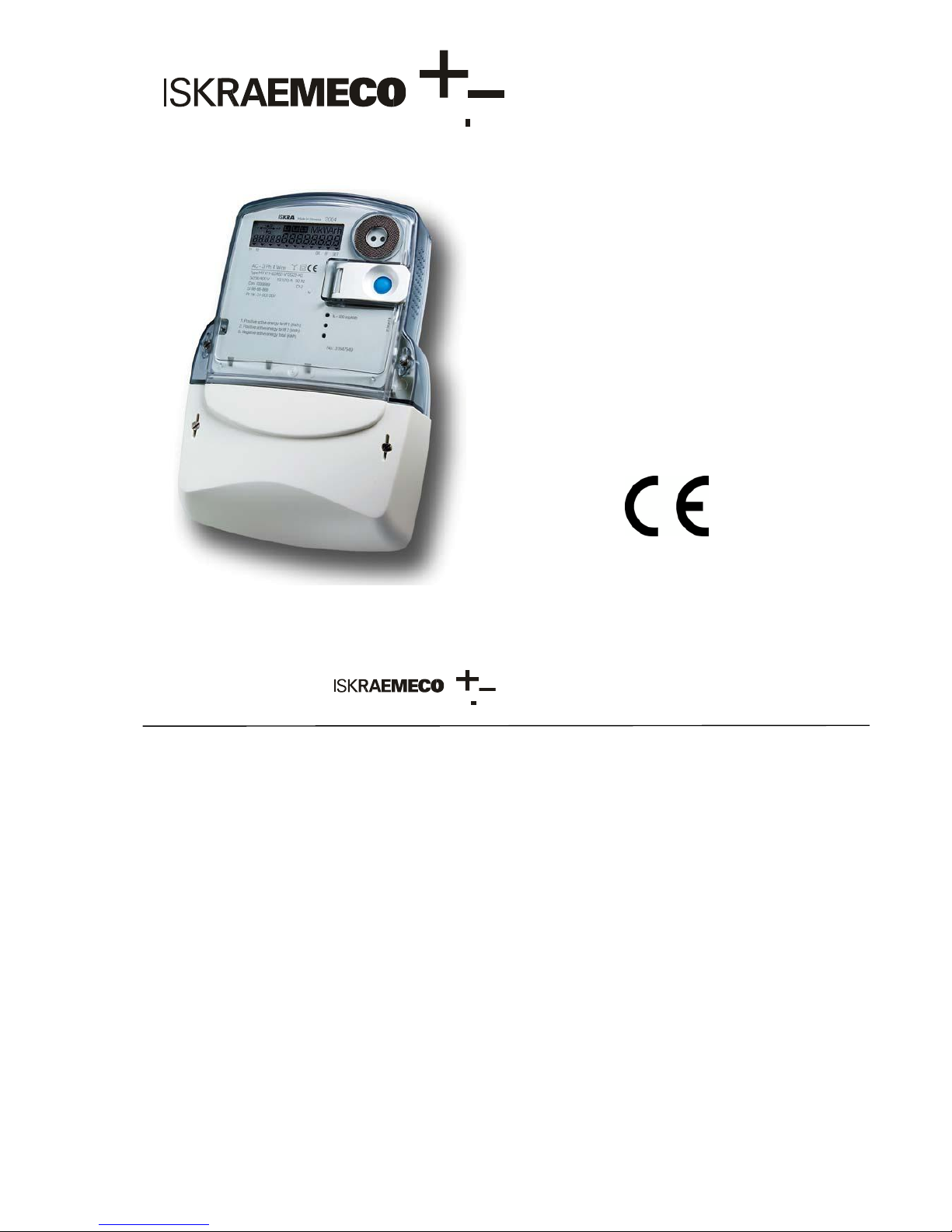
ISKRAEMECO MT174 User Manual
Energy Measurement and Management
MT174
Three-Phase Static Electricity
Multi Tariff Meter
with Maximum Demand Indicator
and Load-profile
MT174 - Electronic three-phase electricity
meters with maximum demand and LP
MT174 - Electronic three-phase
time-of-use electricity meters
The MT174 electronic three-phase meters are
designed for measurement and registration of
active, reactive and apparent energy and
demand in three-phase four-wire networks. They
can be connected directly to the network. The
metering and technical properties of the meters
comply with the EN 50470-1 and -3 European
standards for active energy meters, classes A
and B, as well as with the IEC 62053-21 and IEC
62052-11 international standards for electronic
meters of active energy for classes 1 and 2, and
optionally with the IEC 62053-23 international
standard for electronic meters of reactive energy
for classes 2 and 3.
A built-in time-switch complies with the IEC
62054-21 and IEC 62052-21 standards. It enables
energy registration in up to four tariffs.
The meter software complies with WELMEC 7.2
Issue 1 Software Guide (Measuring Instruments
Directive 2004/22/EC).
The MT174 meters are designed for mechanical
environment M1, electromagnetic environment
E2 and climatic environment -40°C ... +60°C,
relative humidity 95% non-condensing, closed
location. The meters can be installed in any
position.
The meters are designed and manufactured in
compliance with the ISO 9001 (2000) standard.
Energy Measurement and Management
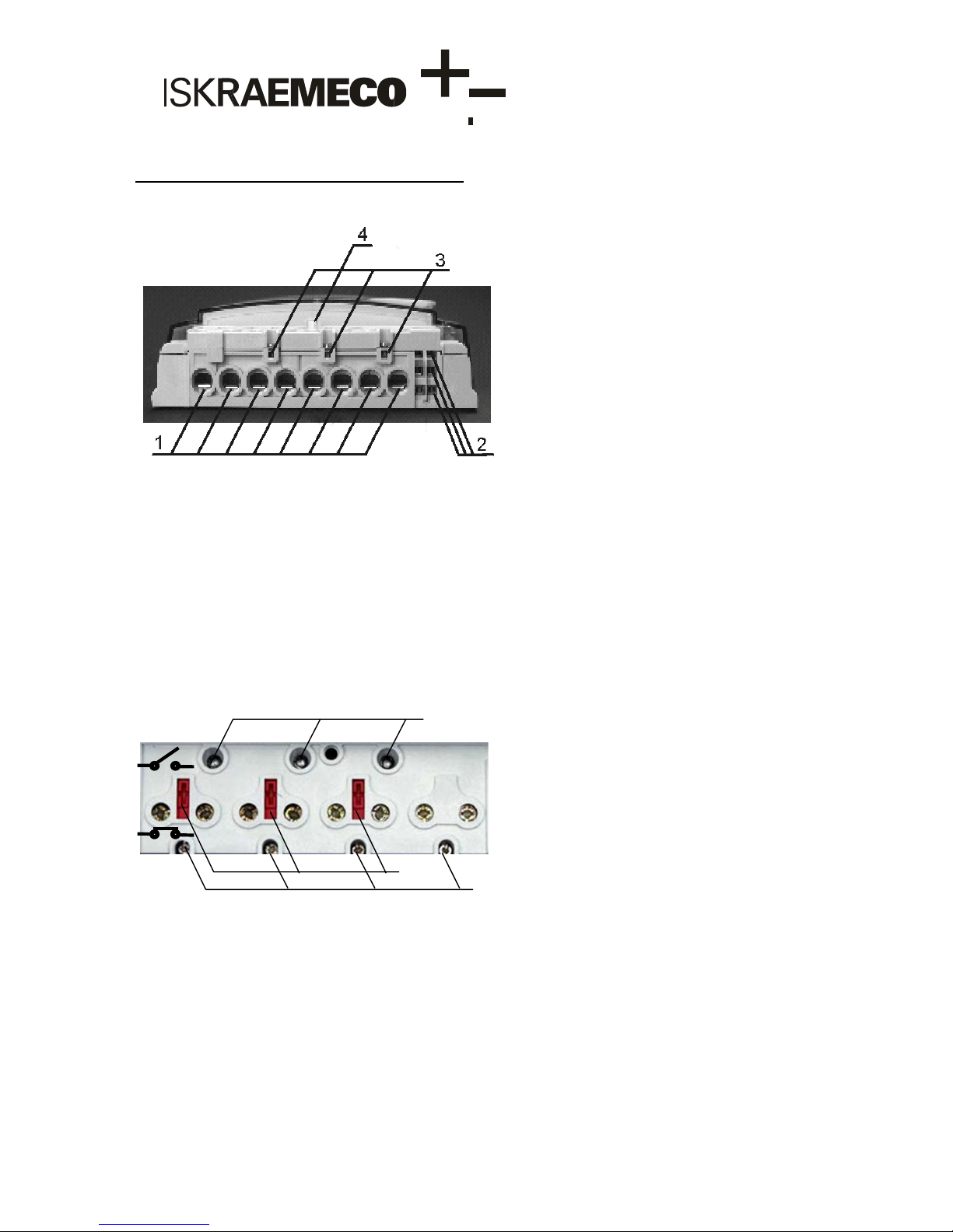
Terminal block for direct connected meters
The terminal block for direct connected meters contains current terminals, auxiliary terminals and potential links
for power supply of the voltage metering circuitry.
Terminal block of direct connected meters
1. Current terminals 3. Auxiliary voltage terminals for an add-on unit
2. Auxiliary terminals 4. Terminal cover opening detector
The 85 A terminal blocks has only one screw per current terminal, while 120 A terminal blocks has
two screws per current terminal. Due to indirect pressure to the conductors the terminal screws do not
damage it. The current terminals make a reliable and durable contact regardless if the conductor is made of
copper or aluminium.
Voltage metering elements are power supplied via potential links. Sliding potential links are self- braking and
enable easy disconnection of current
and voltage metering circuitry. In the metering
mode they should be
in their lowest position (closed contact), and in the meter testing mode they should
be in their highest
position (opened contact). On request, the potential links can be located under the meter cover.
2
1. Sliding potential links
(opened contacts)
1
3
2. Phase voltage test
contacts
3. Terminals of auxiliary voltages
Potential links in the terminal block
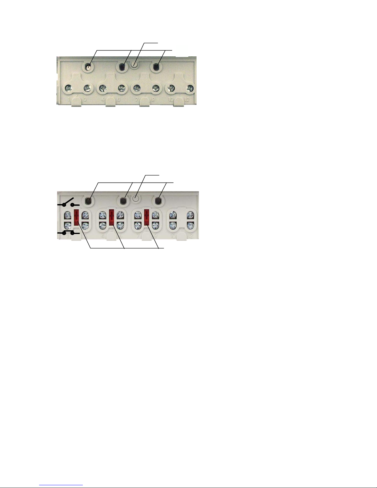
1
2
1. Detector of terminal
cover opening
2. Phase voltage test
contacts
b. Potential links under meter cover
Terminal blocks of direct connected meters for Imax = 85 A
1
2
3
1. Detector of terminal cover opening 2 . Phase voltage test
3. Sliding potential links (opened contacts) contacts
Potential links in the terminal block of direct connect meters for Imax = 120A

Version
Left side
auxiliary
terminals
Right side
auxiliary
terminals
1
Two tariff inputs
Two pulse outputs
2
Two tariff inputs
RS485 interface
3
Two pulse or tariff
outputs
RS485 interface
Terminal block for CT operated meters
The CT operated meters have separate voltage terminals (Fig. 5, item 2) in the terminal block. They are
used for supplying the voltage metering circuitry. The voltage terminals are equal to the current
terminals (Fig. 5, item 1). The current and
voltage terminals are made of solid brass with a 5 mm bore diameter; the conductors are fixed in the
terminals with two screws.
Terminal block of a CT operated meter
4
1 3
2
1. Current terminals 3. Auxiliary terminals
2. Voltage terminals
4. Auxiliary voltage
terminals for add-on unit
Auxiliary Terminals
Up to six auxiliary terminals can be built in a terminal block. They are used for tariff inputs, impulse
outputs or tariff outputs or RS485 interface. Due to a limited number of auxiliary terminals, all stated inputs
and outputs as well as the interface can not be built in the meter at the same time. The bore diameter of the
auxiliary terminals is 3.5 mm. Wires are fixed with a screw. Three auxiliary voltage terminals for power
supply of an external device can be also built-in. The auxiliary terminals are nickel-plated at a tropical
meter version.
The auxiliary terminals enable combinations of the following meter functionalities:
 Loading...