

ISKRAEMECO ME382, MT382 User Manual

ME382 and MT382
Technical description

Technical description
ME382 and MT382
Document code:
EAD 020.615.810
Version:
V2.20
Language:
English
Date:
25.08.2016
COPYRIGHT
© 2016 ISKRAEMECO, d.d. All rights reserved.
No part of this document can be copied, reproduced, transferred, distributed, presented or stored in any
format without the prior written consent of Iskraemeco, d.d., except as otherwise provided in your license or
as expressly permitted in writing by Iskraemeco, d.d.
TRADEMARKS
The Iskraemeco logo, and all related trademarks are registered trademarks or trademarks of Iskraemeco,
d.d. All other trademarks are the property of their respective owners. All rights reserved.
DISCLAIMER AND LIMITATION OF LIABILITY
This Technical description was written for use of ME382 and MT382 meters. This manual, including all
documentation incorporated by reference herein such as documentation provided or made available at
Iskraemeco d.d. web site, is provided or made accessible "AS IS" and "AS AVAILABLE" and without
condition, endorsement, guarantee, representation, or warranty of any kind by Iskraemeco d.d. and its
affiliated companies (hereinafter collectively referred to as »Iskraemeco«). Iskraemeco assumes no
responsibility for any typographical, technical, or other inaccuracies, errors, or omissions in this
documentation, nor for any loss due to the use of this documentation. Iskraemeco reserves the right to
periodically change information that is contained in this documentation; however, Iskraemeco makes no
commitment to provide any such changes, updates, enhancements, or other additions to this documentation.
Iskraemeco shall not be liable for any type of damages related to this documentation or its use, or performance
or non-performance of any software, hardware, service, or any third party products and services.
SAVE AS EXPRESSLY PROVIDED IN YOUR CONTRACT WITH ISKRAEMECO, ISKRAEMECO
EXPRESSLY DISCLAIMS ALL WARRANTIES, EXPRESS OR IMPLIED, INCLUDING, BUT NOT LIMITED
TO THE IMPLIED WARRANTIES OF MERCHANTIBILITY OR FITNESS FOR A PARTICULARE PURPOSE
AND AGAINST INFRINGEMENT. ISKRAEMECO DOES NOT WARRANT THAT THE FUNCTIONS
CONTAINED IN THE PRODUCT WILL BE UNITERRUPTED OR ERROR-FREE, OR THAT DEFECTS IN
THE PRODUCT OR ERRORS IN THE DATA WILL BE CORRECTED. FURTHERMORE, ISKRAEMECO
DOES NOT WARRANT OR MAKE ANY REPRESENTATIONS REGARDING THE USE OR THE RESULTS
OF THE USE OF THE PRODUCT OR ITS DOCUMENTATION IN TERMS OF THEIR CORRECTNESS,
ACCURACY, RELIABILITY, OR OTHERWISE. NO ORAL OR WRITTEN INFORMATION OR ADVICE,
GIVEN BY ISKRAEMECO OR AN ISKRAEMECO AUTHORIZED REPRESENTATIVE SHALL CREATE A
WARRANTY OR IN ANY WAY INCREASE THE SCOPE OF THIS WARRANTY. SOME JURISDICTIONS
DO NOT ALLOW EXCLUSION OF THE IMPLIED WARRANTIES, SO THE ABOVE EXCLUSION MAY NOT
APPLY. UNDER NO CIRCUMSTANCES INCLUDING NEGLIGENCE, SHALL ISKRAEMECO, THEIR
DIRECTORS, OFFICERS, EMPLOYEES OR AGENTS BE LIABLE FOR ANY INCIDENTAL, SPECIAL OR
CONSEQUENTIAL DAMAGES (INCLUDING DAMAGES FOR LOSS OF BUSINESS, LOSS OF PROFITS,
BUSINESS INTERRUPTION, LOSS OF BUSINESS INFORMATION, ETC.) ARISING OUT OF THE USE
OR INABILITY TO USE THE PRODUCT OR ITS DOCUMENTATION, EVEN IF ISKRAEMECO OR AN
ISKRAEMECO AUTHORIZED REPRESENTATIVE HAS BEEN ADVISED OF THE POSSIBILITY OF SUCH
DAMAGES. SOME JURISDICTIONS DO NOT ALLOW LIMITATION OR EXCLUSION OF LIABILITY FOR
INCIDENTAL OR CONSEQUENTIAL DAMAGES OR ALLOW EXCLUSION OR LIMITATION OF LIABILITY
ONLY FOR NEGLIGENCE, BUT NOT FOR GROSS NEGLIGENCE OR WILLFULL MISCONDUCT, SO
THIS LIMITATION MAY NOT APPLY. ISKRAEMECO'S TOTAL LIABILITY FOR ALL DAMAGES, LOSSES
AND CAUSES OF ACTION (WHETHER IN CONTRACT, TORT, INCLUDING NEGLIGENCE, OR
OTHERWISE) SHALL BE DEFINED WITH CONTRACT WITH WHICH YOU BOUGHT PRODUCT OR
SERVICE. IF LIABILITY IS NOT DEFINED WITHIN PREVIOUSLLY MENTIONED CONTRACT
ISKRAEMECO’S LIABILITY FOR ANY AND ALL DAMAGE EVER RELATED TO THIS DOCUMENTATION
SHALL NOT EXCEED (IF NOT OTHERWISE DEFINED WITH APPLICABLE LAW) THE AMOUNT:
1) PAID FOR THE PRODUCT/ SERVICE AND ITS DOCUMENTATION, 2) OF 20% OF THE VALUE OF
THE CUSTOMER’S ORDERS FROM THE LAST 12 MONTHS BEFORE OCCURENCE OF DAMAGE OR
3) 10.000 EUR, WHICHEVER THE LOWEST.
V2.20 – English i/xiv INTRODUCTION

Technical description
ME382 and MT382
ME382-D1
1x230 V, 5(85) A
ME382-D1
1x120 V, 5(85) A
ME382-D3
1x230 V, 10(100) A
ME382-D3
1x120 V, 10(100) A
MT382-D1
3x230/400 V, 5(85) A
MT382-D2
3x230/400 V, 5(120) A
MT382-D2
3x120/208 V, 5(100) A
MT382-T1
3x230/400 V, 5(6) A
ELECTRONIC SINGLE AND THREE-PHASE SYSTEM METER
with GSM/GPRS or UMTS communication module
Technical description
V2.20 – English ii/xiv INTRODUCTION

Technical description
ME382 and MT382
3GPP
3rd Generation Partnership Project
ABS
IA+I + IA-I
AC
Alternating Current
A/D
Analog to Digital
AES
Advanced Encryption Standard
AMM
Automatic Meter Management
APDU
Application Protocol Data Unit
APN
Access Point Name
ASCII
American Standard Code for Information Interchange
BS
British Standard
CAV
Current Average Value
CB
Circuit Breaker
CH
Channel
CII
Consumer Information Interface
CIP
Consumer Information Push
COSEM
COmpanion Specification for Energy Metering
CRC
Cyclic Redundancy Check
CS
Central Server
DCS
Data Coding Scheme
CSD
Circuit Switched Data
DC
Direct Current
DIN
Deutsches Institut für Normung
DLC
Data Line Carrier
DLMS
Device Language Message Specification
DLMS UA
DLMS User Association
DRO
Data ReadOut
DST
Daylight Saving Time
EC
Emergency Credit
EDIS
Energie Daten Identifikations System / Energy Data Identification System
EMC
ElectroMagnetic Compatibility
EN
European Norm
ESC
Escape
FF
Fatal Failure
FIFO
First In First Out
FIPS
Federal Information Processing Standard
FRAM
Ferroelectric Random Access Memory
GCM
Galois/Counter Mode
GIZ
Gesellschaft für Internationale Zusammenarbeit / Society for International Cooperation
i. About the Technical description
The Technical description is intended to present the Mx382 meters (x stands for E (single-phase
meters) or T (three-phase meters)).
The Technical description represents the purpose of the Mx382 meters, meter construction, the way
of deriving the measured quantities and meter functionalities.
The Technical description is intended for technically qualified personnel at energy supply companies,
responsible for system planning and system operation.
ii. Definitions, Acronyms and Abbreviations
V2.20 – English iii/xiv INTRODUCTION

Technical description
ME382 and MT382
GMAC
specialization of GCM for generating a MAC on data that is not encrypted
GMT
Greenwich Mean Time
GND
Ground
GPRS
General Packet Radio Service
GSM
Global System Mobile
HDLC
High-level Data Link Control
HES
Head End System
HEX
Hexadecimal
HHU
Hand Held Unit
HLS
High Level Security
HW
Hard Ware
ICCID
Integrated Circuit Card IDentifier
ID
Identification
IDIS
Interoperable Device Interface Specifications
IE
Iskraemeco
IEC
International Electrotechnical Commission
IEDL
Identity Element Data Length
IEI
Identity Element Identifier
IMEI
International Mobile station Equipment Identity
IP
Internet Protocol
IPv4
Internet Protocol version 4
IR
InfraRed
ISO
International Organization for Standardization
kWh
Kilo Watt-hours
LCD
Liquid Crystal Display
LCP
Link Control Protocol
LED
Light Emitting Diode
LLC
Logical Link Control
LLS
Low Level Security
MAC
Media Access Control address
MB
M-Bus
MC
Manufacturer Code
MCU
Micro Controller Unit
MD5
Message Digest algorithm 5
MDI
Maximum Demand Indicator
MP
Measurement Period
MSB
Most Significant Bit
NCT
No Connection Timeout
NET
IA+I - IA-I
NIST
National Institute of Standards and Technology
NV
Non-Volatile
OBIS
OBject Identification System
OSI
Open System Interconnection
OSM
Other Service Module
PAP
Password Authentication Protocol
PC
Personal Computer
PCB
Printed Circuit Board
PDP
Packet Data Protocol
PDA
Personal Digital Assistant
V2.20 – English iv/xiv INTRODUCTION
Technical description
ME382 and MT382
PDU
Protocol Data Unit
PHY
Physical
PLC
Power Line Carrier
PUP
Power UP
RAM
Random Access Memory
RF
Radio Frequency
RM
Register Monitor
RMS
Root Mean Square
RTC
Real Time Clock
SD
Switching Device (Disconnector, Disconnection device, Load switch)
SAP
Service Access Point
SCA
Service Centre Address
SHA-1
Secure Hash Algorithm
SME
Short Message Entity
SMSC
Short Message Service Centre
SN
Serial Number
SSR
Solid State Relay
SUM
Summation
SQ
Signal Quality
TCP
Transmission Control Protocol
TOU
Time Of Use
UDHI
User Data Header Indicator
UDHL
User Data Header Length
UMTS
Universal Mobile Telecommunications System
UTC
Coordinated Universal Time
UV
Ultra Violet
VDEW
Verband Der ElektrizitätsWirtschaft
WAN
Wireless Area Network
WEEE
Waste Electrical and Electronic Equipment
WIP
Wavecom Internet Protocol
WPDU
Wrapper Protocol Data Unit
NOTE
OBIS (Object Identification System) code (according to DLMS UA 1000-1:2001 standard)
is composed of 6 groups of digits (A-B:C.D.E*F; i.e. 0-0:1.0.0*255). In a case where the
last group of digits (group F) is not written, means the value of F is 255.
iii. Reference documents
Installation and maintenance manual
Iskraemeco’s general terms and condition
V2.20 – English v/xiv INTRODUCTION

Technical description
ME382 and MT382
Date
Version
Update
31.01.2014
1.00
Initial version of the document.
17.09.2014
1.01
Description of the meter type designation was changed.
17.03.2016
2.00
The subchapter 5.1. LCD: Table 20 was updated – new cursor meaning
In the subchapter 7.8. RTC backup: note was added
The subchapter 7.11. Switching device was renew, data changed in the Table 69
The subchapter 7.12.2. Advanced power limitation was added
In the chapter 11. TECHNICAL CHARACTERISTICS data was updated
In the subchapters 11.1. ME382 meter and 11.2. MT382 meter: Backup power
supply, the SuperCap charging time was changed
ME382 and MT382 object lists were updated (see chapters 12.2. Annex 2:
ME382 object list and 12.3. Annex 3: MT382 object list) – new objects in the
lists were added, firmware versions (core, module) were added
Detailed procedure description in the subchapter 6.4.9. Selecting the cellular
network (2G/3G) was added
In the subchapter 5.3.2.1. Data menu example of the register value reading on
the LCD was added
In the subchapter 3.5. Connection diagram connection diagrams were changed
03.05.2016
2.10
In the subchapter 7.7. Alarms two alarms in the Table 66 were added.
Next subchapters were added:
- 7.16.1.3. Asymmetrical voltage (optional)
- 7.16.1.7. Neutral fault (optional)
- 7.16.1.8. Time period for asymmetry voltage and neutral fault
- 7.16.1.9. Capturing of voltage values
New object list in the subchapter 12.3. Annex 3: MT382 object list with new
firmware module version
25.08.2016
2.20
In the subchapter 3.4. Main meter properties bullet modes of energy
measurement and registration at three-phase meters was supplemented with
descriptions of the methods, algebraic method was replaced with arithmetic
method and one new method (absolute) was added.
In the subchapter 3.6.1. Energy paragraph related to the active energy delta
registers was added
NOTE related to rollover in the subchapter 3.7.2.1. Transformer measurement
type was added
In the subchapter 3.7.9. Energy the Table 15 was updated (NET total tariff)
Description about rollover in the subchapter 5.1. LCD was added
The subchapter 5.1.1. Display configuration was added
In the subchapter 7.3. Main load profiles the Table 50 was updated (bit 6, PUP)
The subchapter 7.3.1. Load profiles options was added
The subchapter 7.6.2. Fraud detection log was updated (hold-off period)
In the subchapter 7.8. RTC backup two objects with their descriptions were added
The subchapters 7.10.4. Tariffication script table, 7.10.5. Tariff switch source
and 7.10.6. Manual tariffication script activation were added
The subchapter 7.13. Overvoltage monitor and load disconnection was added
The subchapter 7.16.2. Watchdog counter was added
In the subchapters 12.2. Annex 2: ME382 object list and 12.3. Annex 3: MT382
object list object lists were updated with new objects added
iv. Versioning
V2.20 – English vi/xiv INTRODUCTION

Technical description
ME382 and MT382
TABLE OF CONTENTS
1. SAFETY INFORMATION ........................................................................................................................... 1
1.1. Responsibilities ................................................................................................................................... 1
1.2. Safety instructions ............................................................................................................................... 2
1.2.1. Handling and mounting ................................................................................................................ 2
1.2.2. Meter installation procedure ......................................................................................................... 3
1.2.3. Meter maintenance ...................................................................................................................... 7
2. ENERGY METERING AND MX382 METERS ........................................................................................... 8
3. MX382 METERS INTRODUCTION ........................................................................................................... 9
3.1. Standards and references ................................................................................................................... 9
3.2. ME382 meter description .................................................................................................................. 11
3.2.1. Terminal block constituent parts – ME382-D1 (85 A) DIN connection ...................................... 12
3.2.2. Terminal block constituent parts – ME382-D3 (100 A) BS connection...................................... 12
3.2.3. Terminal block constituent parts – common for D1 (DIN) and D3 (BS) type ............................. 13
3.3. MT382 meter description .................................................................................................................. 14
3.3.1. Terminal block constituent parts – MT382-D1/D2 ..................................................................... 15
3.3.2. Terminal block constituent parts – MT382-T1 ........................................................................... 16
3.4. Main meter properties ....................................................................................................................... 17
3.5. Connection diagram .......................................................................................................................... 19
3.5.1. ME382-D1 meter ........................................................................................................................ 20
3.5.2. ME382- D3 meter ....................................................................................................................... 20
3.5.3. MT382 meter .............................................................................................................................. 21
3.6. Energy and demand registration ....................................................................................................... 22
3.6.1. Energy ........................................................................................................................................ 22
3.6.2. Demand ...................................................................................................................................... 23
3.6.2.1. Other demand registers ...................................................................................................... 25
3.6.2.2. Time management ............................................................................................................ 110
3.7. Measurement platform ...................................................................................................................... 26
3.7.1. Measuring configuration ............................................................................................................. 26
3.7.1.1. Rogowski coil ...................................................................................................................... 27
3.7.1.2. Shunt................................................................................................................................... 27
3.7.2. Energy metrological pulse output .............................................................................................. 27
3.7.2.1. Transformer measurement type ......................................................................................... 27
3.7.3. Measured quantities ................................................................................................................... 28
3.7.4. Voltage ....................................................................................................................................... 29
3.7.4.1. Instantaneous voltage ......................................................................................................... 29
3.7.4.2. Daily peak and minimum values ......................................................................................... 29
3.7.4.3. Average voltage .................................................................................................................. 29
3.7.4.4. Voltage levels ..................................................................................................................... 29
3.7.4.5. Voltage sags and swells ..................................................................................................... 29
3.7.5. Current ....................................................................................................................................... 30
3.7.5.1. Instantaneous current ......................................................................................................... 30
3.7.6. Net frequency ............................................................................................................................. 30
3.7.7. Power ......................................................................................................................................... 30
3.7.7.1. Instantaneous power .......................................................................................................... 30
3.7.7.2. Average power .................................................................................................................... 30
3.7.8. Power factor ............................................................................................................................... 30
3.7.9. Energy ........................................................................................................................................ 31
V2.20 – English vii/xiv INTRODUCTION

Technical description
ME382 and MT382
3.7.9.1. Total energy values ............................................................................................................ 31
3.7.10. Measurement period .............................................................................................................. 31
4. METER CONSTRUCTION ....................................................................................................................... 32
4.1. Technical figures and dimensions of the ME382 meter .................................................................... 32
4.2. Technical figures and dimensions of the MT382 meter .................................................................... 35
4.3. Meter case ......................................................................................................................................... 37
4.3.1. Terminal block ............................................................................................................................ 38
4.3.1.1. U-I link between voltage and current circuits ...................................................................... 38
4.3.1.2. Inputs and outputs .............................................................................................................. 39
4.3.1.2.1. Output for active switching device ................................................................................. 41
4.3.1.2.2. Input/output status .......................................................................................................... 41
4.3.2. Meter cover ................................................................................................................................ 42
4.3.3. Terminal cover ........................................................................................................................... 42
4.4. Name plate ........................................................................................................................................ 44
4.5. Mx382 meter type designation .......................................................................................................... 46
5. CONSOLE ................................................................................................................................................ 47
5.1. LCD ................................................................................................................................................... 47
5.1.1. Display configuration .................................................................................................................. 49
5.2. Metrological LEDs ............................................................................................................................. 50
5.3. Buttons .............................................................................................................................................. 51
5.3.1. Reduced console menu type ..................................................................................................... 52
5.3.1.1. General display readout mode ........................................................................................... 53
5.3.1.2. Alternate display readout mode .......................................................................................... 53
5.3.2. Normal console menu type ........................................................................................................ 54
5.3.2.1. Data menu .......................................................................................................................... 56
5.3.2.2. Set menu ............................................................................................................................ 59
5.3.3. Previous values on a display ..................................................................................................... 61
6. COMMUNICATION .................................................................................................................................. 62
6.1. Optical interface ................................................................................................................................ 62
6.2. P1 interface ....................................................................................................................................... 63
6.2.1. P1 functionality ........................................................................................................................... 64
6.2.2. P1 parameters ........................................................................................................................... 65
6.3. M-Bus ................................................................................................................................................ 65
6.4. GSM/GPRS/UMTS communication module ..................................................................................... 69
6.4.1. Modem initialization ................................................................................................................... 69
6.4.2. GSM/GPRS network diagnostic ................................................................................................. 70
6.4.3. CSD data connection (GSM) ..................................................................................................... 71
6.4.4. Packet data connection (GPRS) ................................................................................................ 72
6.4.5. Short message service (SMS) ................................................................................................... 74
6.4.5.1. SMS initialization ................................................................................................................ 74
6.4.5.2. SMS Application Protocol Data Unit (APDU)...................................................................... 75
6.4.5.3. Outgoing SMS .................................................................................................................... 76
6.4.5.4. Incoming SMS .................................................................................................................... 77
6.4.5.5. SMS Wake-up request (Empty incoming SMS).................................................................. 78
6.4.5.6. Concatenated SMS ............................................................................................................. 78
6.4.6. Modem reset .............................................................................................................................. 79
6.4.7. TCP/IP based COSEM communication profile .......................................................................... 82
6.4.8. GSM/GPRS connection management ....................................................................................... 84
6.4.8.1. Auto connect ....................................................................................................................... 84
V2.20 – English viii/xiv INTRODUCTION

Technical description
ME382 and MT382
6.4.8.2. Auto answer ........................................................................................................................ 85
6.4.9. Selecting the cellular network (2G/3G) ...................................................................................... 88
6.5. Push .................................................................................................................................................. 89
6.5.1. Push objects............................................................................................................................... 89
6.5.2. Data notification service ............................................................................................................. 90
6.5.3. Push process ............................................................................................................................. 90
6.5.4. Push related functionalities ........................................................................................................ 91
7. DESCRIPTION OF MAIN METER FUNCTIONALITIES ......................................................................... 92
7.1. Measurements ................................................................................................................................... 92
7.2. Sequences ........................................................................................................................................ 92
7.3. Main load profiles .............................................................................................................................. 92
7.3.1. Load profile options .................................................................................................................... 94
7.4. Billing ................................................................................................................................................. 94
7.4.1. Billing profile ............................................................................................................................... 95
7.5. Prepayment ....................................................................................................................................... 96
7.6. Event logs .......................................................................................................................................... 99
7.6.1. Standard event log ................................................................................................................... 100
7.6.2. Fraud detection log .................................................................................................................. 101
7.6.3. Disconnector control log .......................................................................................................... 102
7.6.4. M-Bus event log ....................................................................................................................... 103
7.6.5. Power quality log ...................................................................................................................... 104
7.6.6. Communication event log ........................................................................................................ 104
7.6.7. M-Bus master control logs ....................................................................................................... 105
7.6.8. Power failure event log ............................................................................................................ 106
7.6.9. Certification data log ................................................................................................................ 106
7.7. Alarms ............................................................................................................................................. 107
7.8. RTC backup .................................................................................................................................... 109
7.8.1. Time ......................................................................................................................................... 110
7.9. Errors ............................................................................................................................................... 111
7.9.1. Error filter ................................................................................................................................. 112
7.9.2. Error types................................................................................................................................ 112
7.10. Activity calendar and TOU registration ........................................................................................ 113
7.10.1. Activity calendar ................................................................................................................... 114
7.10.2. Tariff program ....................................................................................................................... 114
7.10.3. Tariff synchronization ........................................................................................................... 115
7.10.4. Tariffication script table ........................................................................................................ 115
7.10.5. Tariff switch source .............................................................................................................. 115
7.10.6. Manual tariffication script activation ..................................................................................... 115
7.11. Switching device .......................................................................................................................... 115
7.11.1. Switching device type designation ....................................................................................... 116
7.11.2. Disconnect control ................................................................................................................ 117
7.11.2.1. Manual option ................................................................................................................... 118
7.11.2.1.1. Manual reconnection .................................................................................................. 118
7.11.2.1.2. Manual disconnection ................................................................................................ 119
7.11.2.1.3. By the external button ................................................................................................ 120
7.11.2.2. Remote option .................................................................................................................. 120
7.11.2.2.1. Remote disconnection................................................................................................ 120
7.11.2.2.2. Remote reconnection ................................................................................................. 120
7.12. Limitation ..................................................................................................................................... 121
7.12.1. Limiter ................................................................................................................................... 121
V2.20 – English ix/xiv INTRODUCTION

Technical description
ME382 and MT382
7.12.2. Advanced power limitation ................................................................................................... 122
7.12.3. Supervision monitor – IDIS ................................................................................................... 123
7.12.4. Supervision monitor – GIZ .................................................................................................... 123
7.13. Overvoltage monitor and load disconnection .............................................................................. 124
7.14. Fraud detection ............................................................................................................................ 125
7.14.1. Meter cover open and terminal cover open .......................................................................... 125
7.14.2. Magnetic field detection ........................................................................................................ 125
7.15. Identification numbers ................................................................................................................. 125
7.15.1. COSEM logical device name ................................................................................................ 125
7.15.2. System title ........................................................................................................................... 126
7.15.3. Device number ..................................................................................................................... 126
7.15.4. Device ID .............................................................................................................................. 127
7.15.5. Meter software identification ................................................................................................. 127
7.15.5.1. Software architecture ........................................................................................................ 127
7.15.5.2. E-meter signatures ........................................................................................................... 128
7.16. Monitoring functions .................................................................................................................... 129
7.16.1. Power quality ........................................................................................................................ 129
7.16.1.1. Voltage level ..................................................................................................................... 129
7.16.1.2. Voltage asymmetry ........................................................................................................... 130
7.16.1.3. Asymmetrical voltage (optional) ....................................................................................... 131
7.16.1.4. Asymmetric current ........................................................................................................... 132
7.16.1.5. Unexpected consumption ................................................................................................. 132
7.16.1.6. Neutral missing detection ................................................................................................. 132
7.16.1.7. Neutral fault (optional) ...................................................................................................... 133
7.16.1.8. Time period for asymmetry voltage and neutral fault ....................................................... 133
7.16.1.9. Capturing of voltage values .............................................................................................. 134
7.16.1.10. Power failure ................................................................................................................... 134
7.16.1.11. Wrong phase sequence .................................................................................................. 134
7.16.2. Watchdog counter ................................................................................................................ 135
8. SECURITY ............................................................................................................................................. 136
8.1. Physical security.............................................................................................................................. 136
8.1.1. Seal protection ......................................................................................................................... 136
8.1.2. Parameter protection button .................................................................................................... 137
8.2. Logical security ................................................................................................................................ 137
8.2.1. DLMS/COSEM security ........................................................................................................... 137
9. FIRMWARE UPGRADE ......................................................................................................................... 140
10. APPLICATION ASSOCIATION ......................................................................................................... 142
10.1. SAP assignment .......................................................................................................................... 142
11. TECHNICAL CHARACTERISTICS .................................................................................................... 143
11.1. ME382 meter ............................................................................................................................... 143
11.2. MT382 meter ............................................................................................................................... 146
11.3. Switching device for the MT382 meter ........................................................................................ 149
12. ANNEX ............................................................................................................................................... 150
12.1. Annex 1: Relay, SD and M-Bus disconnect states and transitions ............................................. 150
12.2. Annex 2: ME382 object list .......................................................................................................... 151
12.3. Annex 3: MT382 object list .......................................................................................................... 165
V2.20 – English x/xiv INTRODUCTION

Technical description
ME382 and MT382
INDEX OF FIGURES
Figure 1: Smart metering system ........................................................................................................................................ 8
Figure 2: ME382 meter appearance – front view .............................................................................................................. 11
Figure 3: Terminal block – ME382-D1 (85 A) DIN connection ........................................................................................... 12
Figure 4: Terminal block – ME382-D3 (100 A) BS connection .......................................................................................... 12
Figure 5: Terminal block constituent parts – common for D1 (DIN) and D3 (BS) type ...................................................... 13
Figure 6: MT382 meter appearance – front view ............................................................................................................... 14
Figure 7: Terminal block – MT382-D1/D2 ......................................................................................................................... 15
Figure 8: Terminal block – MT382-T1 ............................................................................................................................... 16
Figure 9: ME38y-D1 meter connection diagram – DIN connection ................................................................................... 20
Figure 10: ME38y-D3 meter connection diagram – BS connection ................................................................................... 20
Figure 11: MT38y meter connection diagram – direct connection (left), transformer connection (right) ............................ 21
Figure 12: Measured energy and demand ........................................................................................................................ 22
Figure 13: Demand calculation sample ............................................................................................................................. 23
Figure 14: Measuring principle .......................................................................................................................................... 23
Figure 15: Attributes in the case of block demand (1 period) ............................................................................................ 24
Figure 16: Attributes in case of sliding demand ................................................................................................................. 24
Figure 17: Time attributes when measuring sliding demand ............................................................................................. 25
Figure 18: Overall and fixing dimensions of the ME382-D1 meter fitted with a regular terminal cover .............................. 32
Figure 19: Overall and fixing dimensions of the ME382-D3 meter fitted with a regular terminal cover .............................. 32
Figure 20: Overall and fixing dimensions of the ME382-D1 meter fitted with a short terminal cover ................................. 33
Figure 21: Overall and fixing dimensions of the ME382-D3 meter fitted with a short terminal cover ................................. 33
Figure 22: Overall and fixing dimensions of the ME382-D1 meter fitted with a P1+M-Bus terminal cover ........................ 34
Figure 23: Overall and fixing dimensions of the ME382-D3 meter fitted with a P1+M-Bus terminal cover ........................ 34
Figure 24: Overall and fixing dimensions of an MT382 meter fitted with a regular terminal cover ..................................... 35
Figure 25: Overall and fixing dimensions of an MT382 meter fitted with a short terminal cover ........................................ 35
Figure 26: Overall and fixing dimensions of the MT382 meter fitted with an external SD terminal cover .......................... 36
Figure 27: Overall and fixing dimensions of the MT382 meter fitted with a P1+M-Bus+SD terminal cover ....................... 37
Figure 28: Sliding U-I link (left: position down; right: position up) ...................................................................................... 39
Figure 29: Load control terminal ........................................................................................................................................ 39
Figure 30: Signal control terminal ...................................................................................................................................... 40
Figure 31: Mx382 input terminals ...................................................................................................................................... 41
Figure 32: Output for active SD ......................................................................................................................................... 41
Figure 33: Short terminal cover (left) and regular terminal cover (right) ............................................................................ 42
Figure 34: External SD terminal cover for the meter with SD unit (left) and P1+M-Bus+SD terminal cover (right)............ 43
Figure 35: P1+M-Bus terminal cover (left: with the sealable lid; right: without the sealable lid) ........................................ 43
Figure 36: Meter connection diagram on the inner side of the terminal cover ................................................................... 43
Figure 37: Name plate of the ME382 meter ...................................................................................................................... 44
Figure 38: Name plate of the MT382 meter ....................................................................................................................... 45
Figure 39: Full Mx382 LCD – display fields ....................................................................................................................... 47
Figure 40: Displaying value with format “60“ ..................................................................................................................... 48
Figure 41: Displaying value with format “82“ ..................................................................................................................... 48
Figure 42: Signature on the display ................................................................................................................................... 49
Figure 43: LEDs at the ME382 meter ................................................................................................................................ 50
Figure 44: LEDs at the MT382 meter ................................................................................................................................ 50
Figure 45: Scroll button (on the left) Reset and Scroll button (on the right) ....................................................................... 51
Figure 46: Menu navigation diagram – Reduced console menu type ................................................................................ 53
Figure 47: Entering the Data/Set menu ............................................................................................................................. 55
Figure 48: Data menu navigation ...................................................................................................................................... 56
Figure 49: Alternate display readout mode navigation in Normal console menu type ....................................................... 56
Figure 50: Load profile on display navigation .................................................................................................................... 58
Figure 51: Certification data log on display navigation ...................................................................................................... 59
Figure 52: Set menu navigation ........................................................................................................................................ 60
Figure 54: LCD test mode navigation ................................................................................................................................ 60
Figure 55: Previous values navigation in Alternate display readout mode ........................................................................ 61
Figure 56: Optical interface (left); optical sonda (right) ................................................................................................ ...... 62
Figure 57: Diagram for connecting devices to the P1 port................................................................................................. 63
V2.20 – English xi/xiv INTRODUCTION

Technical description
ME382 and MT382
Figure 58: P1 port connection ........................................................................................................................................... 64
Figure 59: M-Bus master-slave configuration and dongle interface .................................................................................. 66
Figure 60: Example for channel ........................................................................................................................................ 67
Figure 61: State transitions during a successful call establishment procedure ................................................................. 72
Figure 62: GPRS connection establishment process ........................................................................................................ 73
Figure 63: SMS short wrapper .......................................................................................................................................... 75
Figure 64: IDIS client and server model ............................................................................................................................ 76
Figure 65: State diagram during modem restart procedure ............................................................................................... 81
Figure 66: TCP/IP based COSEM communication profiles ............................................................................................... 82
Figure 67: The COSEM wrapper protocol data unit (WPDU) ............................................................................................ 82
Figure 68: Auto connect operation in »Always ON« modes during defined time window .................................................. 84
Figure 69: Auto connect operation in modes 103 and 104 when a connection method is invoked ................................... 85
Figure 70: Prepayment function with statuses ................................................................................................................... 96
Figure 71: Credit transfer data structure............................................................................................................................ 97
Figure 72: Token protocol data unit processing phases .................................................................................................... 97
Figure 73: Event handling ................................................................................................................................................. 99
Figure 74: Alarm reporting process ................................................................................................................................. 107
Figure 75: Time and Date Data Format ........................................................................................................................... 110
Figure 76: Error filtering................................................................................................................................................... 112
Figure 77: Graphical tariff program ................................................................................................................................. 113
Figure 78: Example of switching device for MT382 (left: top view; right: front view) ....................................................... 116
Figure 79: MT382 meter with switching device ............................................................................................................... 117
Figure 80: The “ConnEct” notice on the LCD .................................................................................................................. 118
Figure 81: The “EntEr” notice on the LCD ....................................................................................................................... 118
Figure 82: Switching device manual reconnection diagram ............................................................................................ 118
Figure 83: The “dISconn” notice on LCD ......................................................................................................................... 119
Figure 84: Switching device manual disconnection diagram ........................................................................................... 119
Figure 85: Limiter diagram .............................................................................................................................................. 121
Figure 86: Advanced power limitation diagram ............................................................................................................... 122
Figure 87: Terminal cover opening switch ....................................................................................................................... 125
Figure 88: COSEM Logical Device Name Structure ........................................................................................................ 125
Figure 89: Identification Structure ................................................................................................................................... 128
Figure 90: Revision Number Structure ............................................................................................................................ 128
Figure 91: Asymmetrical voltage detection...................................................................................................................... 131
Figure 92: Unexpected consumption ............................................................................................................................... 132
Figure 93: Intended neutral N-N' ..................................................................................................................................... 132
Figure 94: Neutral fault detection .................................................................................................................................... 133
Figure 95: Power fail example ......................................................................................................................................... 134
Figure 96: Positions of the seals at ME382 meter (left) and MT382 meter (right) ........................................................... 136
Figure 97: Encryption and decryption procedure ............................................................................................................. 137
Figure 98: Three-step upgrading procedure .................................................................................................................... 141
Figure 99: Firmware image transfer process ................................................................................................................... 141
Figure 100: Relay, switching device and M-Bus disconnect state transitions.................................................................. 150
V2.20 – English xii/xiv INTRODUCTION

Technical description
ME382 and MT382
INDEX OF TABLES
Table 1: Auxiliary terminals designation ............................................................................................................................ 19
Table 2: Last average demand registers ........................................................................................................................... 25
Table 3: Maximum demand registers – total ..................................................................................................................... 25
Table 4: Cumulative maximum demand registers ............................................................................................................. 26
Table 5: Average demand objects ..................................................................................................................................... 26
Table 6: Measuring configuration type .............................................................................................................................. 26
Table 7: List of a metropulse output functions ................................................................................................................... 27
Table 8: Peak and minimum values of voltage .................................................................................................................. 29
Table 9: Average values of voltage ................................................................................................................................... 29
Table 10: Voltage levels counters ..................................................................................................................................... 29
Table 11: Magnitude for voltage sags and swells .............................................................................................................. 29
Table 12: Magnitude of last voltage sag and swell ............................................................................................................ 29
Table 13: Instantaneous power objects ............................................................................................................................. 30
Table 14: Average power .................................................................................................................................................. 30
Table 15: Total and tariff energy objects ........................................................................................................................... 31
Table 16: Input state control register of ME382 and MT382 meter ................................................................................... 41
Table 17: Output state control register of single-phase (ME382) meter ............................................................................ 42
Table 18: Output state control register of three phase (MT382) meter .............................................................................. 42
Table 19: Meter type designation ................................ ................................ ................................................................ ...... 46
Table 20: LCD cursors ...................................................................................................................................................... 48
Table 21: Display Configuration for Octet 0 definition ....................................................................................................... 49
Table 22: Display Configuration for Octet 1 definition ....................................................................................................... 49
Table 23: LED constants recommendation ....................................................................................................................... 50
Table 24: Button labels...................................................................................................................................................... 51
Table 25: Use of Scroll button in Reduced console menu type ......................................................................................... 52
Table 26: Scroll button extended press ............................................................................................................................. 52
Table 27: Use of buttons in Normal console menu type .................................................................................................... 54
Table 28: Register reading procedure on the LCD when the Reduced console menu type is set ..................................... 57
Table 29: Register reading procedure on the LCD when the Normal console menu type is set........................................ 57
Table 30: RJ11 pins .......................................................................................................................................................... 64
Table 31: M-Bus profile status registers notifications ........................................................................................................ 67
Table 32: M-Bus alarms .................................................................................................................................................... 69
Table 33: GSM/GPRS modem diagnostics objects ........................................................................................................... 70
Table 34: Network signal strength ..................................................................................................................................... 70
Table 35: GSM status object bit assignment ..................................................................................................................... 71
Table 36: SMS centre address phone number setting ...................................................................................................... 74
Table 37: Phone number example .................................................................................................................................... 75
Table 38: Push setup list ................................................................................................................................................... 76
Table 39: DCS Settings ..................................................................................................................................................... 77
Table 40: VP Settings........................................................................................................................................................ 77
Table 41: Example of SMS PDU for setting object 0-0:96.13.0 ......................................................................................... 78
Table 42: Concatenated SMS ........................................................................................................................................... 78
Table 43: Modem reset triggers ........................................................................................................................................ 80
Table 44: COSEM Wrapper header information ................................................................................................................ 83
Table 45: Auto connect modes .......................................................................................................................................... 85
Table 46: Modem working mode ................................ ................................ ................................................................ ....... 86
Table 47: Window status ................................................................................................................................................... 86
Table 48: GSM status object bits B1 and B11 relation states and meaning ...................................................................... 87
Table 49: GSM network name ........................................................................................................................................... 88
Table 50: Profile status register ......................................................................................................................................... 93
Table 51: Load profile options bit values ........................................................................................................................... 94
Table 52: Event log objects ............................................................................................................................................. 100
Table 53: List of events in the Standard event log .......................................................................................................... 101
Table 54: List of events in the Fraud detection event log ................................................................................................ 102
Table 55: List of events in the Disconnector control log .................................................................................................. 102
Table 56: List of events in the M-Bus event log ............................................................................................................... 103
V2.20 – English xiii/xiv INTRODUCTION

Technical description
ME382 and MT382
Table 57: List of events in the Power quality event log ................................................................................................... 104
Table 58: List of events in the Communication event log ................................................................................................ 105
Table 59: List of events in the M-Bus control log ............................................................................................................. 105
Table 60: Power Failure Event Log ................................................................................................................................. 106
Table 61: Last Modified Secure Parameter Identifier ...................................................................................................... 106
Table 62: Last Modified Secure Parameter Old Value .................................................................................................... 106
Table 63: Last Modified Secure Parameter New Value ................................................................................................... 106
Table 64: Monitored critical parameters .......................................................................................................................... 107
Table 65: Alarm 1 codes ................................................................................................................................................. 108
Table 66: Alarm 2 codes (IDIS P2) .................................................................................................................................. 109
Table 67: IDIS error codes register ................................................................................................................................. 111
Table 68: IE error codes register ..................................................................................................................................... 112
Table 69: Type designation for ZO350-D1/D2 ................................................................................................................. 116
Table 70: The IDIS Device Type Meaning....................................................................................................................... 126
Table 71: The IDIS Function Type Meaning .................................................................................................................... 126
Table 72: COSEM logical device name example ............................................................................................................ 126
Table 73: Meter device IDs ............................................................................................................................................. 127
Table 74: Meaning of Revision Number Characters ........................................................................................................ 128
Table 75: Dip & swell detection model ............................................................................................................................ 129
Table 76: Daily peak and minimum counters .................................................................................................................. 130
Table 77: Set of supported clients ................................................................................................................................... 138
Table 78: Supported authentication mechanism names ................................................................................................. 138
Table 79: Application context names .............................................................................................................................. 139
Table 80: Security suite ................................................................................................................................................... 139
Table 81: COSEM SAP assignment example ................................................................................................................. 142
Table 82: Disconnect control modes ............................................................................................................................... 150
V2.20 – English xiv/xiv INTRODUCTION
Technical description
ME382 and MT382
DANGER: for a possibly dangerous situation, which could result in severe physical injury
or fatality – attention to high-risk hazards.
WARNING: attention to a medium risk hazards.
CAUTION: for a possibly dangerous situation, which could result in minor physical injury
or material damage - attention to a low risk hazards.
Operating instruction: for general details and other useful information.
1. SAFETY INFORMATION
Safety information used in this Technical description are described with the following symbols and pictograms:
All safety information in this Technical description describes the type and source of danger; it is possible
consequences and measures to avoid the danger.
1.1. Responsibilities
The owner of the meter is responsible to assure that all authorized persons who work with the meter read
and understand the parts of the Technical description and Installation and maintenance manual that explains
safe handling with the meter.
The personnel must be sufficiently qualified for the work that will be performed. The installation personnel
must possess the required electrical knowledge and skills, and must be authorised by the utility to perform
the installation procedure.
The personnel must strictly follow the safety regulations and operating instructions, written in the individual
chapters in the Installation and maintenance manual and the Technical description.
The owner of the meter is responsible specially for the protection of the persons, for prevention of material
damage and for training of personnel.
V2.20 – English 1/179 1. SAFETY INFORMATION
Technical description
ME382 and MT382
1.2. Safety instructions
1.2.1. Handling and mounting
At the beginning of installation at the metering point, the meter should be carefully taken out of the box
where it was packed. This should prevent the meter from falling as well as any other external or internal
damage to the device and personal injuries. Should such an incident occur despite all precautions the meter
may not be installed at the metering point as such damage may result in different hazards. In such case, the
meter needs to be sent back to the manufacturer for examination and testing.
CAUTION: The edges of the seals, sealing wires as well as some edges under (removed) terminal cover are
sharp!
CAUTION: The temperature of the terminal block of the connected and operating meter may rise, therefore
the temperature of the terminal cover may rise as well.
DANGER: In case of any damage inside the meter (fire, explosion...) do not open the meter.
CAUTION: The meter may be used only for the purpose of measurement for which it was produced.
Any misuse of the meter will lead to potential hazards.
WARNING: Safety measures should be observed at all times. Do not break the seals or open the meter at
any time!
It must be consulted in all cases where symbol is marked in order to find out the nature of the
potential hazards and any actions, which have to be taken to avoid them.
The meter installation procedure is described in the Installation and maintenance manual. For safety reasons
the following instructions should be followed.
See the complete Technical description for detailed technical features of ME382 and MT382 meters
and its intended use.
V2.20 – English 2/179 1. SAFETY INFORMATION

Technical description
ME382 and MT382
Only a properly connected meter can measure correctly! Every connection error could result in a
financial loss for the power company!
1.2.2. Meter installation procedure
DANGER: The ME382/MT382 electricity meter is a device connected into the electricity network. Any
unauthorized manipulation of the device is dangerous for life and prohibited according to the
applicable legislation. Any attempt to damage the seals as well as any unauthorized opening of the
terminal or meter cover is strictly forbidden.
Installation companies shall implement a training policy that ensures that all installers are adequately trained,
understand risk and safety issues and possess the relevant skills before they commence operational duties.
The installer will need to recognise and understand different metering installations, meter types and various
equipment associated with those installations applicable to the successful installation of the electricity meter.
The installer must consult and comply with local regulations and read the installation instructions
written in the Installation and maintenance manual before installation.
The Installation and maintenance manual provides the instructions for installing ME382/MT382 meters.
The document provides a short overview of the meter, details of device installation and set-up, installation
considerations, and health and safety considerations.
The installer will be considered as a public face by both the power company and its customers. The installer
shall adopt the highest standards of behaviour and be respectful to clients and members of the public.
Before the beginning of the installation procedure, check if the metering point is correctly prepared for meter
installation. The metering point must always be left clean and in order.
The work location shall be defined and clearly marked. Adequate working space as well as means of access
and lighting shall be provided at all parts of an electrical installation on, with, or near which any work activity
is to be carried out.
Where necessary, safe access to the work location shall be clearly marked.
The metering point must not be exposed to running water or fire.
Meter installation may not be performed by unauthorised and untrained personnel. Such persons are not
allowed to cut the seals and open the terminal or meter cover as contact with the live parts of the meter is
dangerous for life.
Opening the terminal or meter cover is dangerous for life because there are live parts inside.
Installation personnel must possess the required electrical knowledge and skills, and must be authorised by
the utility to perform the installation procedure.
The installer is obligated to perform the installation procedure in accordance with the national legislation and
internal norms of the utility.
National legislation can set out the minimum age and the competence criteria for installers. In case there are
no national requirements defined, the following criteria shall be used by assessing the competence of
installers: knowledge of electricity, experiences on electrical work, understanding of the installation
V2.20 – English 3/179 1. SAFETY INFORMATION

Technical description
ME382 and MT382
procedures, practical experience of that work, understanding the hazards which can arise during the work
and the precautions to be observed, ability to recognize at all times whether it is safe to continue working.
According to the basic principles, either the nominated person in control of the electrical installation or the
nominated person in control of the work activity shall ensure that specific and detailed instructions are given
to the personnel carrying out the work before starting and on completion of the work.
Before starting work, the nominated person in control of the work activity shall give notification to the
nominated person in control of the electrical installation, of the nature, place and consequences to the
electrical installation of the intended work.
CAUTION: The installer is expected to fully understand the risks and safety issues involved in
electrical installations. The installer shall be aware at all times of the potential hazard of electrical
shock and shall exercise due caution in completing the task!
Tools, equipment and devices shall comply with the requirements of relevant National or International
Standards where these exist. Tools, equipment and devices shall be used in accordance with the
instructions and/or guidance provided by the manufacturer or supplier.
Any tools, equipment and devices provided for the purpose of safe operation of, or work on, with, or near
electrical installations shall be suitable for that use, be maintained and be properly used.
Personnel shall wear clothing suitable for the locations and conditions where they are working. This could
include the use of close-fitting clothing or additional PPE (personal protective equipment).
CAUTION: The installer must be correctly equipped with personal protection equipment (PPE) and
use the appropriate tools at all times during the installation.
Working procedures are divided into three different procedures: dead working, live working, and working in
the vicinity of live parts. All these procedures are based on the use of protective measures against electric
shock and/or the effects of short-circuits and arcing.
The installer must be informed if the national legislation permits the work on the installation under
voltage – live work, and must follow the rules of legislation.
Depending on the kind of work, the personnel working in such conditions shall be instructed or
skilled. Live working requires the use of specific procedures. Instructions shall be given how to
maintain tools, equipment and devices in good working order and how to verify them before working.
This subclause deals with the essential requirements (“the five safety or golden rules”) for ensuring that the
electrical installation at the work location is dead and secure for the duration of the work.
This shall require clear identification of the work location. After the respective electrical installations have
been identified, the following five essential requirements shall be undertaken in the specified order unless
there are essential reasons for doing otherwise: disconnect completely (1.), secure against re-connection
(2.), verify that the installation is dead (3.), carry out earthing and short-circuiting (4.) and provide protection
against adjacent live parts (5.).
V2.20 – English 4/179 1. SAFETY INFORMATION
Technical description
ME382 and MT382
CAUTION: Do not attempt to install the meter before you have isolated the installation site from the
network!
DANGER: The relevant preliminary fuses must be removed before making any modifications to the
installation, and kept safe until completing the work to prevent the unnoticed reinsertion.
DANGER: Secondary circuit of current transformer must not be opened when current is flowing in the
primary circuit. This would produce a dangerous voltage of several thousand volts at the terminals and the
insulation of the transformer would be destroyed.
DANGER: Connecting the meter into the network under voltage is dangerous for life so the conductors at the
metering point must not be connected to any voltage source during the connection procedure. The meter
connection procedure may only be performed by well-trained and adequately authorized personnel.
CAUTION: Only one wire or ferrule may be connected in one terminal. Otherwise, the terminal could be
damaged or the contact could not be made properly.
CAUTION: Use only prescribed types of cables for the installation!
DANGER: The insulation of the connecting cable must extend over the whole visible part of the cable.
There must be no further bare part of the cable visible above the terminal edge. Touching live parts is
dangerous for life. The stripped part of the connecting wire should be shortened if necessary.
CAUTION: At the end of installation at the metering point, no cable should stay unconnected or hanging
freely from the metering point.
The meter has to be mounted on a smooth vertical surface and fixed at 2 or 3 points with screws using the
proper torque (the meter has two attachment holes and, optionally, a top hanger).
V2.20 – English 5/179 1. SAFETY INFORMATION
Technical description
ME382 and MT382
The meter is intended to be mounted at an indoor metering point, in a meter cabinet, secured against the
undesired access of unauthorized persons. Only scroll push button may be accessible from the outside.
Do not expose meter surface to very high temperatures even though the surface is made of non-flammable
plastics to prevent fire.
Electrical connection: mounting cables must be properly dimensioned and of proper shape. They must be
mounted using the proper torque. The meter should be connected according to the meter connection
diagram that is attached to the inner side of the meter terminal cover. Screws on the current terminal must be
tightened with proper torque.
CAUTION: If it is possible to install the meter without isolation from the network, i.e. on live network, then
appropriate instructions and safety warnings shall be provided.
CAUTION: Specific aspects and safety hazards related to external voltage and current transformers,
auxiliary supplies and local generation shall be covered.
DANGER: The preliminary fuses and/or voltage arresters must be re-inserted before commissioning and
functional check of the meter.
Seals on the meter have to be checked at the end of the installation procedure so that the final customer
cannot come into contact with live parts of the meter.
DANGER: If the terminal cover is not screwed tight, there exists a danger of contact with the connection
terminals. Contact with live parts of the meter is dangerous for life.
CAUTION: For safety reasons, place the terminal cover immediately after the installation procedure and fix it
with fixing screws!
DANGER: Switch on the power. Beware of the risk of electric shock at all times!
The functional check requires voltage to be applied and load applied to all phases. Determine first the energy
flow direction.
If no main voltage is present, commissioning and functional check must be performed at a later date.
V2.20 – English 6/179 1. SAFETY INFORMATION
Technical description
ME382 and MT382
1.2.3. Meter maintenance
No maintenance is required during the meter’s lifetime. The implemented metering technique, built-in
components and manufacturing procedures ensure high long-term stability of meters. Therefore, no
recalibration is required during entire meters lifetime.
In case the service of the meter is needed, the requirements from the meter installation procedure
must be observed and followed.
Cleaning of the meter is allowed only with a soft dry cloth. Cleaning is allowed only in upper part of the meter
– in the area of the LCD (Liquid Crystal Display). Cleaning is forbidden in the area of terminal cover, where
cables are connected to the meter. Cleaning can be performed only by the personnel responsible for meter
maintenance.
CAUTION: Never clean soiled meters under running water or with high-pressure devices. Penetrating
water can cause short circuits. A damp cleaning cloth is sufficient to remove normal dirt such as
dust. If the meter is more heavily soiled, it should be dismounted and sent to the responsible service
or repair centre.
Visible signs of fraud attempt (mechanical damages, presence of a liquid, etc.) must be regularly checked.
The quality of seals and the state of the terminals and connecting cables must be regularly checked.
If there exists a suspicion of incorrect operation of the meter, the local utility must be informed immediately.
DANGER: Breaking the seals and removing the terminal cover or meter cover will lead to potential
hazards because there are live electrical parts inside.
After the end of the meter’s lifetime, the meter should be treated according to the Waste Electrical
and Electronic Equipment (WEEE) Directive!
V2.20 – English 7/179 1. SAFETY INFORMATION
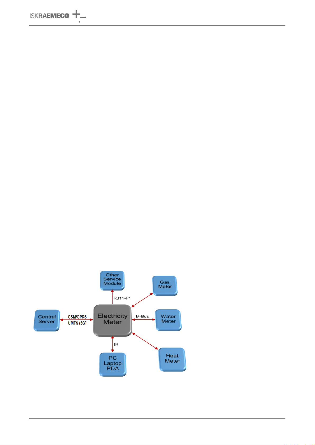
Technical description
ME382 and MT382
2. ENERGY METERING AND Mx382 METERS
Mx382 family meters are designed for up to eight tariff measuring of active, reactive and apparent energy in
one or two energy flow directions. The meter measures consumed energy in three-phase four-wire networks
for direct or indirect connection.
Measuring and technical characteristics of the meter comply with the IEC 62052-11 and IEC 62053-21
international standards for electronic active energy meters, class 1 and 2, and reactive energy meters,
classes 2 or 3 in compliance with IEC 62053-23 as well as a standard for time switches IEC 62052-21.
Meters are designed and manufactured in compliance with the standards and ISO 9001 as well as more
severe Iskraemeco standards.
Meter utilizes the DLMS communication protocol in compliance with the IEC 62056-46 standard as well as
IEC 62056-21.
The Mx382 meters are members of the fourth generation of Iskraemeco electronic single and three-phase
meters for a deregulated market of electric power, with the following common functional properties:
time-of-use (TOU) measurement of active energy and maximum demand (in up to 8 tariffs),
load profile (LP) registration,
liquid crystal display (LCD),
internal real-time clock (RTC),
two push buttons: Reset and Scroll button,
optical port (IEC 62056-21 standard) for local meter programming and data downloading,
P1 port for sending data to in-house display (IHD),
built-in GSM/GPRS or UMTS (3G) modem for a remote two-way communication,
two inputs (alarm input, external button input),
impulse output,
6 A bi-stable relay output,
M-Bus for reading up to 4 other meters (heat, gas, water meters),
integrated switching device at single-phase meters and external switching device at three-phase
meters (option) for remote disconnection/reconnection of the customer premises,
remote connection and disconnection the energy supply of individual customers (option),
the external magnetic field detector,
the meter cover opening (MCO) and the terminal cover opening (TCO) detector.
Figure 1: Smart metering system
V2.20 – English 8/179 2. ENERGY METERING AND Mx382 METERS

Technical description
ME382 and MT382
DIN 43857-1
Elektrizitätszähler in Isolierstoffgehäusen für unmittelbaren Anschluß bis 60A
Grenzstromm; Hauptmaße für Wechselstromzähler
DIN 43857-2
Elektrizitätszähler in Isolierstoffgehäusen für unmittelbaren Anschluß bis 60A
Grenzstromm; Hauptmaße für Drehstromzähler
DIN 43863-3
Elektrizitätszähler; Tarifgeräte als Zusatzeinrichtung zum Elektrizitätszähler EDIS
(Energie-Daten-Identifikations-System)
BS 7856
Code of practice for Design of alternating current, watthour meters for active energy
(classes 1 and 2)
EN 13757-2
Communication systems for meters and remote reading of meters
Part 2: Physical and link Layer
EN 13757-3
Communication systems for meters and remote reading of meters
Part 3: Dedicated application Layer
EN 13757-4
Communication systems for meters and remote reading of meters Part 4: Wireless
meter readout (Radio Meter reading for operation in the 868-870 MHz SRD band)
EN 50022
Hutschienen 35mm breit zur Schnappbefestigung von Geraten
EN 50160
Voltage characteristics of electricity supplied by public electricity networks, 2010
EN 50470-1
Electricity metering equipment (a.c.) - Part 1: General requirements, tests and test
conditions Metering equipment (class indexes A, B and C)
EN 50470-3
Electricity metering equipment (a.c.) - Part 3: Particular requirements - Static meters
for active energy (class indexes A, B and C)
EN 61000-4-6
Electromagnetic compatibility (EMC) - Part 4-6: Testing and measurement
techniques-
Immunity to conducted disturbances, induced by radio-frequency fields
EN 61000-4-18
Testing and measurement techniques - Damped oscillatory wave immunity test
IEC 60068-2-75
Environmental testing - Part 2: Tests - Test Eh: Hammer tests
IEC 61000-4-2
Electromagnetic compatibility (EMC) - Part 4-2: Testing and measurement
techniques- Electrostatic discharge immunity test
IEC 61000-4-3
Electromagnetic compatibility (EMC) - Part 4-3: Testing and measurement
techniques-
Radiated, radio-frequency, electromagnetic field immunity test
IEC 61000-4-4
Electromagnetic compatibility (EMC) - Part 4-4: Testing and measurement
techniques- Electrical fast transient/burst immunity test
IEC 61000-4-5
Electromagnetic compatibility (EMC) - Part 4-5:Testing and measurement
techniques- Surge immunity test
IEC 61038
Time switches for tariff and load control
IEC 62056-21
Data exchange for meter reading, tariff and load control - Direct local connection
(3rd edition of IEC 61107)
IEC 62056-46
Electricity metering; Data exchange for meter reading, tariff and load control; Data
link layer using HDLC-Protocol
IEC 62056-47
Electricity metering; Data exchange for meter reading, tariff and load control; COSEM
transport layers for IPv4 networks
IEC 62056-53
Electricity metering; Data exchange for meter reading, tariff and load control COSEM
Application Layer
IEC 62056-61
Electricity metering; Data exchange for meter reading, tariff and load control obis
object identification system (OBIS)
IEC 62053-21
Electricity metering equipment; Particular requirements; Electronic meters for active
energy (classes 1 and 2)
IEC 62053-23
Electricity metering equipment (AC.); Particular requirements; Static meters for
reactive energy (classes 2 and 3)
3. Mx382 METERS INTRODUCTION
3.1. Standards and references
V2.20 – English 9/179 3. Mx382 METERS INTRODUCTION

Technical description
ME382 and MT382
IEC 62052-11
Electricity metering equipment (AC.): General requirements, tests and test conditions
- Metering equipment
IEC 62052-21
Electricity metering equipment (AC.) General requirements, tests and test conditions
- Tariff and load control equipment
IEC 61334-4-32
Distribution automation using distribution line carrier systems - Data communication
protocols - Data link layer - Logical link control (LLC)
IEC 60529
Degrees of protection provided by enclosures (IP code)
ISO/IEC 8802.2
Information technology - Telecommunications and information exchange between
systems - Local and metropolitan area networks - Specific requirements; Logical link
control
IDIS 2
IDIS package 2, IP profile, Edition 2.0 (including G3-PLC), 03-09-2014
NIST
Recommendation for Block Cipher Modes of Operation: Galois/Counter Mode (GCM)
and GMAC, November 2007
RFC 1321
MD5 (Message Digest algorithm 5)
RFC 1332
The Internet Protocol Control Protocol (IPCP)
RFC 1700
Assigned Numbers
RFC 3241
Robust Header Compression
DSMR
Dutch Smart Meter Requirements, V3.0
FIPS PUB 180-1
Secure Hash Standard (SHA-1), 1993
COSEM Blue Book 12th Edition, DLMS UA 1000-1:2014, Ed. 12.0
COSEM Green Book 8th Edition, “DLMS/COSEM – Architecture and Protocols”, DLMS User
Association, DLMS UA 1000-2 Ed. 8.0, 2014-07-07
VDEW-specification for “Electronic Meters with load curve“ Version 2.1.2 7th November 2003
WELMEC
WELMEC 7.2, Software guide, Measuring Instruments Directive 2014/32/EU,
page 77
V2.20 – English 10/179 3. Mx382 METERS INTRODUCTION
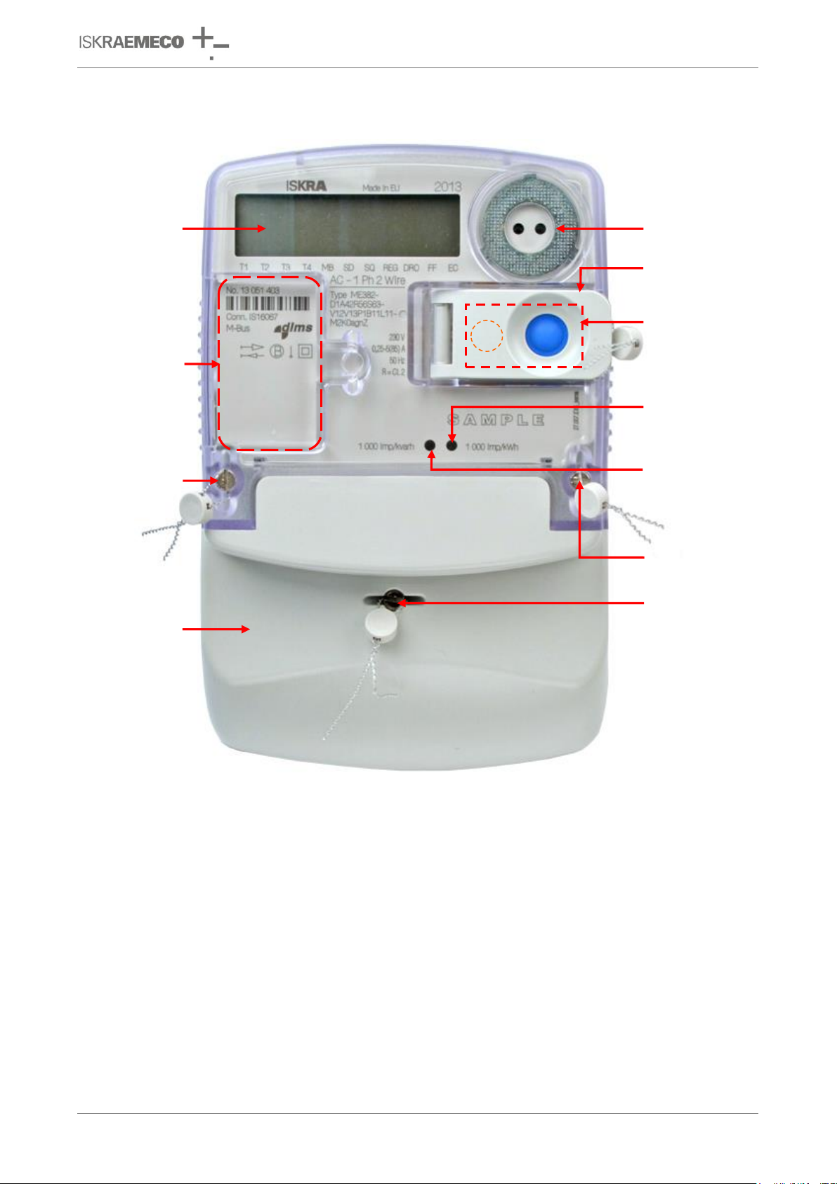
Technical description
ME382 and MT382
liquid crystal
display (LCD)
meter cover
sealing screw
terminal cover
IR optical interface
button cover
sealing door
Scroll and
Reset buttons
accuracy test LED
for active energy
accuracy test LED
for reactive/apparent
energy
meter cover
sealing screw
terminal cover
sealing screw
place for
external antenna
coupling device
3.2. ME382 meter description
Figure 2: ME382 meter appearance – front view
V2.20 – English 11/179 3. Mx382 METERS INTRODUCTION
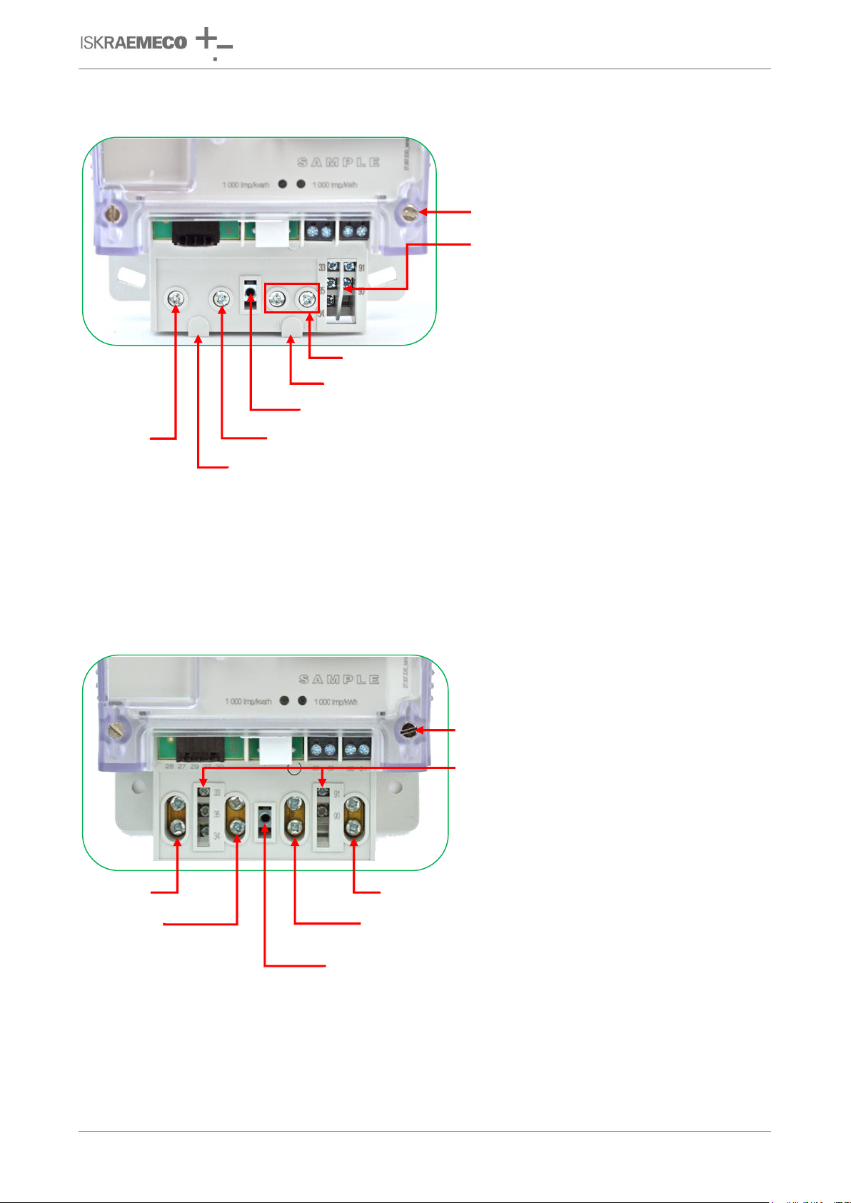
Technical description
ME382 and MT382
meter cover sealing screw
(tightening torque 0,2–0,4 N m)
Neutral – in, Neutral – out
terminal cover fixing point
L – out
L – in
Voltage L (optional)
Neutral (optional)
auxilary terminals:
- left: signal control output – 33
neutral – 35
- right: M-Bus – 91, 90
meter cover sealing screw
(tightening torque 0,2–0,4 N m)
L – in
L – out
Neutral – out
Neutral – in
terminal cover fixing point
auxilary terminals:
- left: signal control output – 33
load control output – 34,
neutral – 35
- right: M-Bus – 90, 91
3.2.1. Terminal block constituent parts – ME382-D1 (85 A) DIN connection
load control output – 34,
Figure 3: Terminal block – ME382-D1 (85 A) DIN connection
3.2.2. Terminal block constituent parts – ME382-D3 (100 A) BS connection
Figure 4: Terminal block – ME382-D3 (100 A) BS connection
V2.20 – English 12/179 3. Mx382 METERS INTRODUCTION
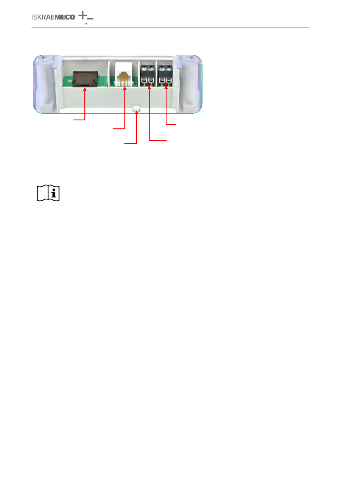
Technical description
ME382 and MT382
NOTE
For detailed information, see the Installation and maintenance manual.
external button input (50, 51)
socket for P1 port
alarm input (85, 80)
terminal cover
opening detector
SIM card holder
3.2.3. Terminal block constituent parts – common for D1 (DIN) and D3 (BS) type
Figure 5: Terminal block constituent parts – common for D1 (DIN) and D3 (BS) type
V2.20 – English 13/179 3. Mx382 METERS INTRODUCTION
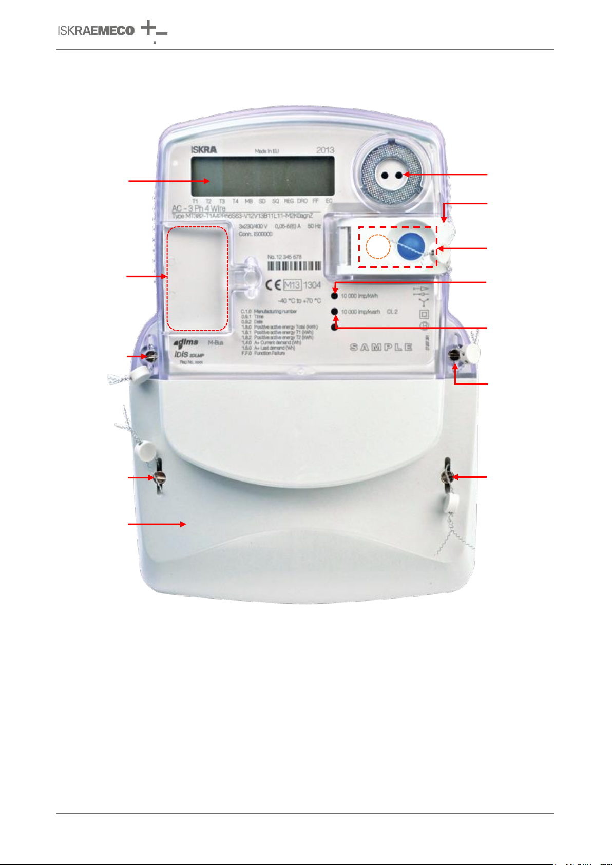
Technical description
ME382 and MT382
liquid crystal
display (LCD)
meter cover
sealing screw
meter cover
sealing screw
terminal cover
sealing screw
accuracy test
LED for reactive/
apparent
energy
accuracy test
LED for active
energy
Scroll and
Reset buttons
IR optical
interface
terminal cover
sealing screw
button cover
sealing door
terminal
cover
place for
external antenna
coupling device
3.3. MT382 meter description
Figure 6: MT382 meter appearance – front view
V2.20 – English 14/179 3. Mx382 METERS INTRODUCTION
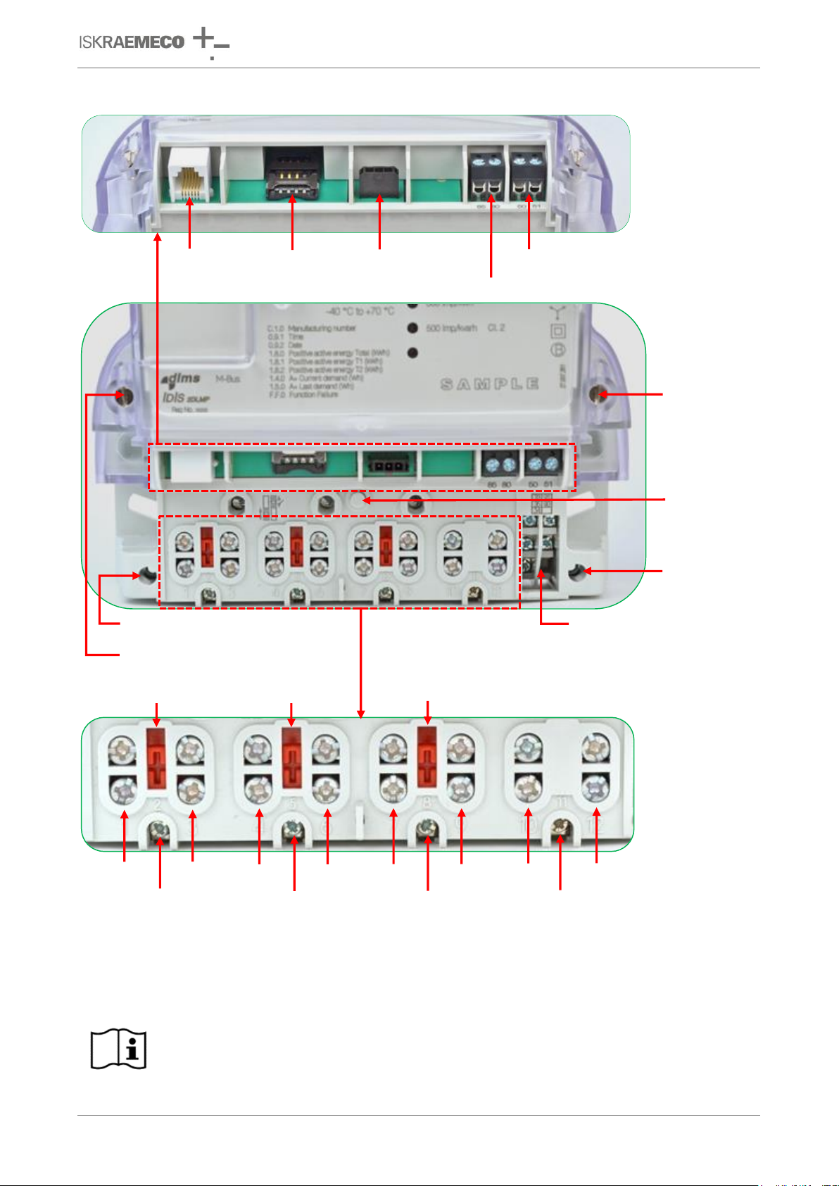
Technical description
ME382 and MT382
NOTE
For detailed information, see the Installation and maintenance manual.
meter cover
sealing screw
(0,2-0,4N m)
switching
device
connector
socket for
P1 port
external button input (50, 51)
alarm input (85, 80)
SIM card
holder
terminal cover fixing point
meter cover sealing screw
(0,2-0,4N m)
terminal cover
opening detector
U-I link
L1
in
L1
out
L1
aux
U-I link
U-I link
L2
in
L2
out
L2
aux
L3
in
L3
out
L3
aux
N
in
N
out
N
aux
auxilary terminals:
- left: signal control output – 33
load control output – 34,
neutral – 35
- right: M-Bus – 90, 91
terminal cover
fixing point
3.3.1. Terminal block constituent parts – MT382-D1/D2
Figure 7: Terminal block – MT382-D1/D2
V2.20 – English 15/179 3. Mx382 METERS INTRODUCTION
 Loading...