

ISKRAEMECO ME371, MT371, ME372, MT372, ME374 Technical Description
1994
-
2009
ME371,
MT371
Single- and Three-Phase
Electronic Meters with Built-in
DLC Communication Channel
ME372,
MT372
Single- and Three-phase
Electronic Meters with Built-in
GSM/GPRS Modem or RS485
Communication Interface
ME374
Single-phase Electronic
Meters with Built-in RF
communication interface
Technical
Description
LAD 020.611.325
Version 3.00, 21.05.2009
Mx37y
B0024445
KOMAR DOBERLET
5.6.2009
020611325_003_000_AD.doc
LAD
Mx37y TECHNICAL DESCRIPTION
Mx37y TEHNIČNI OPIS
020.611.325
1/45 3.

1994
-
2009
Content:
Revision history.................................................... 3
Mx37y – Single- and Three-phase electronic
meters.................................................... 4
1.
1.1 Multi-tariff registration................................ 7
1.2 Power measurement ................................. 7
1.3 Load-profile................................................ 7
1.4 Supplied energy or power limitation.......... 7
1.5 Code red.................................................... 8
1.6 Prepaid functionality.................................. 8
2.
2.1 Meter case (ME37y)................................ 10
2.2 Overall and fixing dimensions (ME37y)... 11
2.3 Meter configuration (ME37y)................... 11
2.4 Metering system (ME37y) ....................... 12
3.
3.1 MT371….................................................. 13
3.2 MT372….................................................. 13
3.3 Meter case (MT37y) ................................ 13
3.4 Overall and fixing dimensions (MT371)... 15
3.5 Overall and fixing dimensions (MT372)... 16
3.6 Meter configuration (MT37y) ................... 17
3.7 Metering system (MT37y)........................ 17
4.
4.1 Power supply unit.................................... 19
4.2 Microcontroller with FRAM ...................... 19
4.3 Real-time clock (RTC)............................. 20
4.4 Liquid Crystal Display – LCD................... 20
4.5 LED.......................................................... 21
4.6 Push-buttons ........................................... 22
4.7 Communication channels........................ 24
KOMAR DOBERLET
Energy measurement and registration7
Meter appearance (ME37y) ................ 10
Meter appearance (MT37y)................. 13
Meter configuration ............................ 19
4.2.1 Load-profile recorder............................ 19
4.2.2 Log-book .............................................. 19
4.2.3 Keeping of billing results ...................... 20
4.3.1 Time-of-use registration ....................... 20
4.3.2 Maximum demand................................ 20
4.4.1 Data display.......................................... 20
4.4.2 Signal flags........................................... 21
4.6.1 RESET and SCROLL push-button....... 22
4.6.2 Manual meter billing reset.................... 24
4.7.1 Optical port – IR communication interface
25
4.7.2 DLC modem (Mx371)........................... 25
4.7.3 Integrated GSM/GPRS communication
interface with antenna (option) (Mx372)25
4.7.4 RF communication interface (ME374) . 25
4.7.5 RS485 communication interface (option)
(Mx372)................................................ 26
B0024445
5.6.2009
020611325_003_000_AD.doc
4.7.6 M-Bus communication interface (option)26
4.7.7 Readout via built-in communication
4.8 AMR readout............................................ 26
4.9 Inputs and outputs (ME37y) .................... 27
4.10 Inputs and outputs (MT37y).....................27
5.
5.1 On request reading of E-meter................29
5.2 Billing registers reading of E-meter ......... 29
5.3 Scheduled reading of E-meter................. 29
5.4 Historic reading of E-meter...................... 29
5.5 On request reading of G-meter................ 29
5.6 Billing registers reading of G-meter.........29
5.7 Scheduled reading of G-meter ................ 29
5.8 Historic reading of G-meter ..................... 29
5.9 Device status...........................................29
5.10 Tariff structure configuration of E-meter..30
5.11 Remote customer connection/disconnection
5.12 Load-profile reading of E-meter............... 30
5.13 Load-profile reading of G-meter .............. 30
5.14 Load-profile configuration of E-meter...... 30
5.15 Load-profile configuration of G-meter...... 31
5.16 Power quality...........................................31
5.17 Power failure registration......................... 31
5.18 Alarms...................................................... 31
5.19 Commission E-meter...............................32
5.20 Security....................................................32
6.
7.
7.1 Connection procedure of GSM/GPRS
7.2 Connection procedure of RF communication
8.
9.
10.
10.1 Position of the seals ................................ 37
10.2 Wire seals................................................ 37
11.
12.
12.1 Meter connection of ME37y meters......... 39
12.2 Communication interface – M-Bus .......... 39
12.3 Meter connection of MT37y meters.........39
13.
14.
Mx37y TECHNICAL DESCRIPTION
interfaces.............................................. 26
4.9.1 Alarm inputs .........................................27
4.9.2 Load control output............................... 27
4.10.1 Inputs .............................................. 28
4.10.2 Outputs ...........................................28
Additional meter functions ................ 29
30
Data protection.................................... 33
Meter connection procedure ............. 34
communication interface..........................34
interface................................................... 34
Accessory for meters managing....... 35
Meter maintaining ............................... 36
Anti-fraud protection .......................... 37
Front plate ...........................................38
Meter connection ................................ 39
Technical data.....................................41
Type designation ................................44
Mx37y TEHNIČNI OPIS
Mx37y
LAD
020.611.325
2/45 3.
1994
-
2009
Revision history
Version
1.00 12.10.2007
Date Comment
Initial version
2.00 29.05.2008
3.00 21.05.2009
Double-cage clamp, Capacity of the load-profile recorder 1 and 2, Billing
profiles 1 and 2, Alarm inputs, List of error statuses, List of events in
event log, Anti-fraud protection, Front plate, Type designation,
standards EN 50470–1 and EN 50470–3
ME374 added
Mx37y
B0024445
KOMAR DOBERLET
5.6.2009
020611325_003_000_AD.doc
Mx37y TECHNICAL DESCRIPTION
Mx37y TEHNIČNI OPIS
LAD
020.611.325
3/45 3.

1994
-
2009
Mx37y – Single- and Three-phase
electronic meters
The Mx37y single- and three-phase electronic
meters are designed for measuring and registration
of active, reactive and apparent energy in single
phase or in three-phase four- or three-wire network
for direct and indirect connection. Measuring and
technical characteristics of meters comply with the
IEC 62052-11 and IEC 62053-21 international
standards for electronic active energy meters, class
1 or 2 (MID, class B or A) , and reactive energy
meters, classes 2 or 3 in compliance with IEC
62053-23 as well as a standard for time switches
IEC 62052-21.
Measuring and technical characteristics of the
meters also comply with the MID standards: EN
50470–1 (Electricity metering equipment - General
requirements, tests and test conditions - Metering
equipment: class indexes A, B and C) and EN
50470–3 (Electricity metering equipment - Particular
requirements - Static meters for active energy: class
indexes A, B and C).
Meters are designed and manufactured in
compliance with the standards and ISO 9001 as well
as more severe Iskraemeco standards.
The Mx37y meters are the third generation of
Iskraemeco electronic single- and three-phase
meters for a deregulated market of electric power,
with the following common functional properties:
• Time-of-use measurement of active energy
and maximum demand (in up to 4 tariffs)
• Load-profile registration
• LCD in compliance with the VDEW
specification
• Internal real-time clock
• Two push-buttons: Reset and Scroll
• Optical port in compliance with the IEC
62056-21 standard for local meter
programming and data downloading
• Built-in interface or a modem for remote
meter programming and data downloading
• Impulse output
• M-Bus – multi-utility (option)
• Plug-in switching device (option)
• Prepayment functionality (option)
• Limitation of supplied energy or power
(option)
• Code red (option)
• Remote connection and disconnection of
energy supply to individual customers
(option)
The first generation of Iskraemeco electronic meters
for a deregulated market of electric power, i.e. the
Mx42y meters were provided with RS232 or RS485
interface for remote two-way communication, and
utilized IEC 62056-21, mode C communication
protocol.
The second generation of Iskraemeco electronic
meters for a deregulated market of electric power,
i.e. the Mx351 was provided with an integrated DLC
modem for two-way communication via low voltage
distributions network - or upon request - RS485
interface instead, for remote two-way
communication. It utilized the DLMS communication
protocol in compliance with the IEC 62056-51
standard as well as IEC 62056-21, mode C protocol.
These meters had the following additional functional
properties:
• Indication of incorrect connection,
• Bistable relay for demand control
• Two S0 impulse inputs (option).
The third generation of Iskraemeco electronic singleand three-phase meters for a deregulated market of
electric power consists of Mx37y meter types: with
built-in DLC communication channel (Mx371) or
GSM/GPRS modem – or upon request – with RS485
interface instead (Mx372) or RF communication
interface (ME374), for remote two-way
communication.
The meter utilizes the DLMS communication protocol
in compliance with the IEC 62056-46 standard as
well as IEC 62056-21, mode C protocol. Further to
the Mx37y meters functionality they also include:
• Detectors of the meter and the terminal
cover opening
• Switching device for remote disconnection /
reconnection at the customer premises
(option)
• M-Bus for reading other meters (heat, gas,
water)
Mx37y
B0024445
KOMAR DOBERLET
5.6.2009
020611325_003_000_AD.doc
Mx37y TECHNICAL DESCRIPTION
Mx37y TEHNIČNI OPIS
LAD
020.611.325
4/45 3.
1994
-
2009
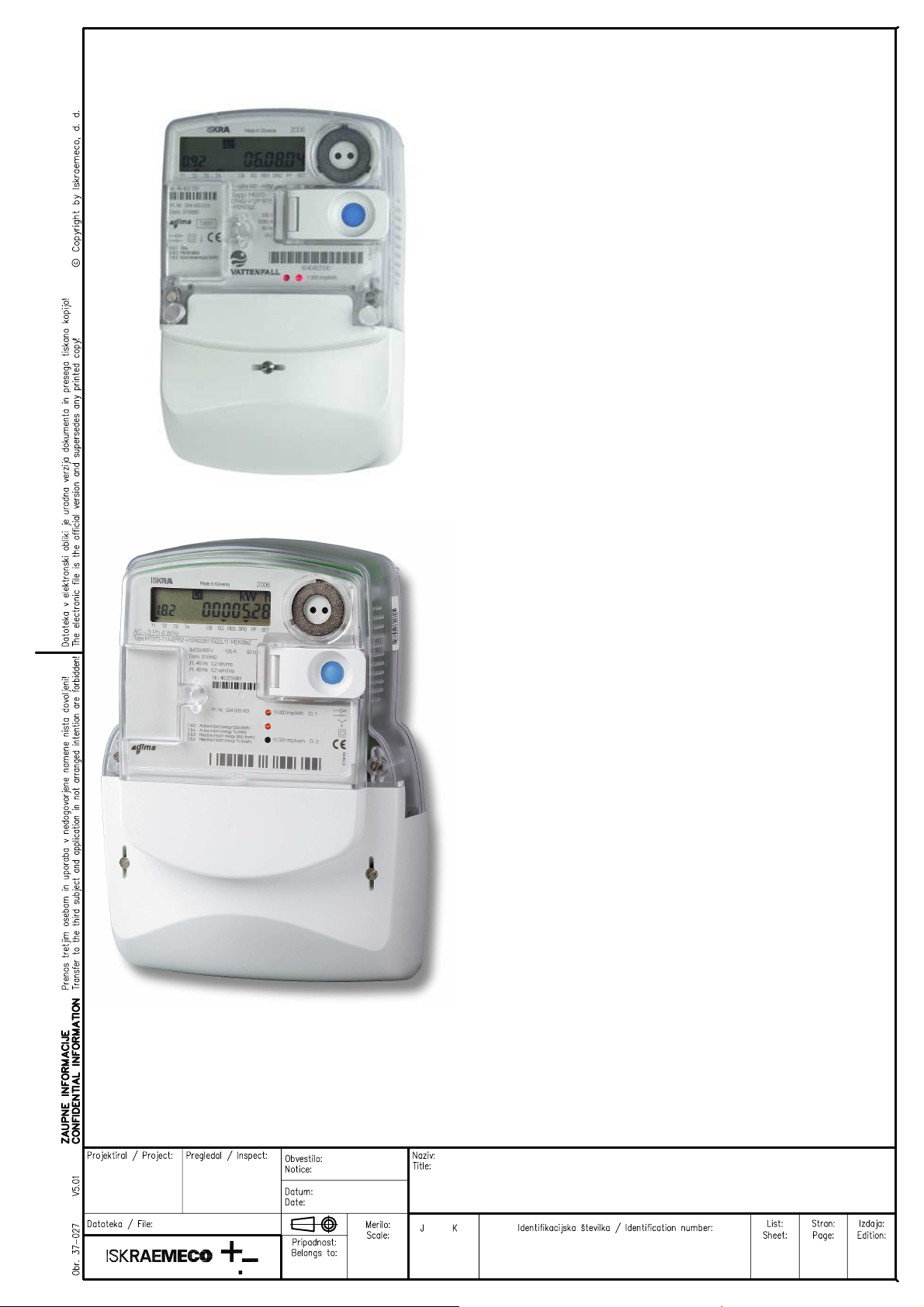
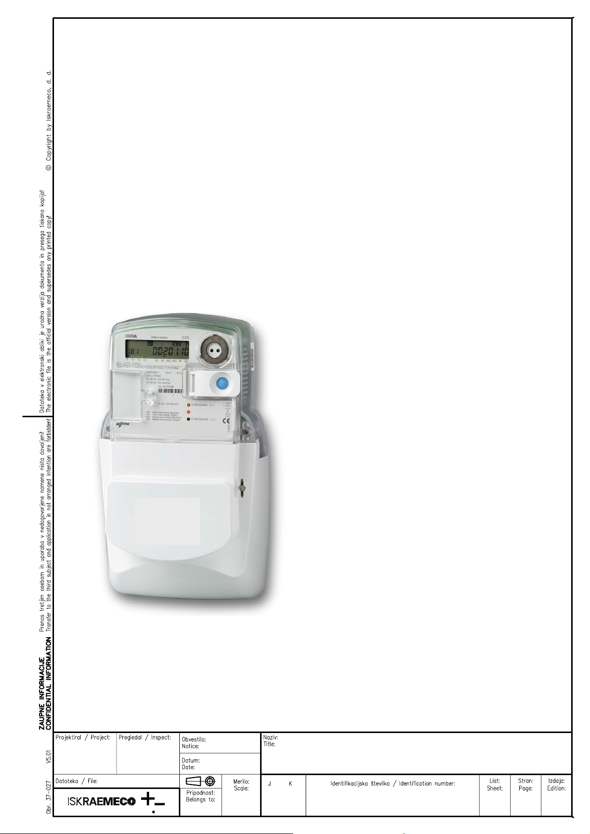
Fig. 1: MT371 meter with ZO3 plug-in switching device
Mx37y meters properties:
• Active energy and demand meter
Accuracy class 1 or 2
• Reactive energy meter
Accuracy class 2 or 3
• Apparent energy meter
• Modes of energy measurement and
registration (single-phase meters)
For one-way energy flow direction
For two-way energy flow direction
For two-way energy flow direction but
registered in one (absolute) register
• Modes of energy measurement and
registration (three-phase meters)
For one-way energy flow direction, three-phase
energy is algebraic sum of energies registered
in each of the phases – meters are equipped
with an electronic reverse running stop
For two-way energy flow direction, three-
phase energy is algebraic sum of energies
registered in each of the phases
For one-way energy flow direction, three-
phase energy is sum of absolute values of
energies registered in each of the phases
• Meter connection to network
The three-phase meter can function as a singlephase or a two-phase meter
• Meter quality:
Due to high accuracy and long-term stability
of metering elements no meter re-calibration
over its life is required
High meter reliability
High immunity to EMC
• Additional meter functions:
Current measurement in a neutral conductor
via the fourth measuring system:
Detection of missing/broken neutral conductor
Detection of phase and voltage unbalance
Measurement and registration of under- and
over-voltage
Generation of alarms and their transmitting
via the DLC modem and low voltage network
(“alarm pull” at Mx371 – the concentrator
reads Alarm ON status and Alarm OFF status
register from the meter) or via GSM/GPRS
modem or the RS485 communication
interface or via RF communication interface
(“alarm push” at Mx372 or ME374 – GSM
modem or RF communication interface
constantly reads Alarm ON status and Alarm
OFF status register from the meter and, if
any alarm is active and enabled, it tries to
notify the centre about the alarm)
• Time-of-use registration (up to 4 tariffs):
Tariffs change-over; internal real-time clock
• Load-profile recorder:
Two load-profile recorders (i.e. daily and
hourly values)
• Communication channels:
Infrared optical port in compliance with the
IEC 62056-21 for local meter programming
and data downloading
Built-in DLC modem (Mx371)
GSM/GPRS modem (Mx372) or
Built-in RS485 comm. interface (Mx372)
Built-in RF communication interface (ME374)
Built-in M-Bus comm. interface (option)
• LCD:
In compliance with the VDEW specification
• Data display modes:
Automatic cyclic data display with display
time of 10 sec.
Manual data display mode (by pressing the
Scroll push-button)
Mx37y
B0024445
KOMAR DOBERLET
5.6.2009
020611325_003_000_AD.doc
Mx37y TECHNICAL DESCRIPTION
Mx37y TEHNIČNI OPIS
LAD
020.611.325
5/45 3.
1994
-
2009
• Indicators:
on LCD:
- Presence of phase voltages L1, L2, L3
- Phase currents flow direction
- Actual tariff indication
- Status of switching device
- Meter status and alarms
- 3-state GSM signal level indicator (Mx372)
LED1: Imp / kWh
LED2: Imp / kVArh
• Communication protocols:
Optical port: IEC 62056 – 21, mode C or
DLMS (in compliance with IEC 62056 – 46)
DLC modem (Mx371): DLMS by IEC 62056–46
GSM/GPRS modem (Mx372); IEC 62056 – 46
RF communication interface (ME374);
IEC 62056 – 46
RS485 Interface (Mx372); IEC 62056 – 46
Identification system; IEC 62056 – 61
COSEM organization of data: IEC 62056-53
M-Bus: EN 13757-2 and EN 13757-3
• OBIS data identification code: IEC 62056–61
• Auxiliary inputs / outputs:
Output for load control with a 6 A relay
Output for load control with an OptoMOS relay
Alarm input (low voltage)
M-Bus interface to which up to 4 gas, heat or
water meters can be connected (also a switching
device ZO340-D1)
Two impulse outputs or an output for control of
a switching device (ZO320-D1)
• Automatic configuration of an AMR system:
Meters are registered automatically into an
AMR system (Intelligent Network Management)
• Automatic meter setting into the repeater
mode (DLC repeater) :
Each meter can automatically enter into the
repeater mode and transmit data in both
directions, even with meters with which it can
not communicate directly.
Data transmission of max. 7 remote meters
which temporarily operate in the repeater
mode increases efficiency of communication
and distance between the meters and a data
concentrator.
• Call-back (Mx372 and ME374):
The meter can perform a call and send a
message to the centre:
- After installation
- If a pre-defined alarm condition exists (e.g.
after Power Down/Up event)
- If a signal appears on the alarm input
• Programming:
Programming of the meter as well as Firmware
upgrade can be done locally (via an optical port)
or remotely (via GSM modem – Mx372 or via
RF communication interface – ME374) in
compliance with the predefined security levels.
• Detection of meter and terminal cover
opening
1. Simple and fast meter installation
• Current terminals:
Make good contact with current conductors
irrespective of their design and material
Do not damage conductors
• Voltage terminals:
Internal and/or external connection
A sliding bridge (for simple separation of a
voltage part from a current part)
• Compact plastic meter case:
Made of high quality self-distinguishing UV
stabilized material that can be recycled
IP54 protection against dust and water
penetration (by IEC 60529)
Mx37y
B0024445
KOMAR DOBERLET
5.6.2009
020611325_003_000_AD.doc
Mx37y TECHNICAL DESCRIPTION
Mx37y TEHNIČNI OPIS
LAD
020.611.325
6/45 3.
1994
-
2009
1.
Energy measurement and
registration
The meter measures and records electric energy:
• In a single-phase two-wire network (also
MT37y)
• Three-phase three-wire network (MT37y)
• Three-phase four-wire network: (MT37y)
total (∑ Li)
only positive active energy
positive and negative active energy (A+, A-)
separately
absolute active energy A
only positive reactive energy
positive and negative reactive energy (R+,R-)
separately
apparent energy
Meters are provided with two LEDs on the front plate.
They are intended for checking the meter accuracy.
Impulse constant depends on the meter version
(direct or current transformer meter).
defined with hour and minute. Minimal resolution
between changeovers is one minute.
Different combinations of the tariff program are
avaliable:
• Up to 4 tariff rates (8 rates as an option)
• Up to 4 seasons
• Up to 4 day types (8 as an option)
• Up to 8 individual changeovers inside individual
daily program
• Up to 32 programmable holidays
• Support to lunar holidays in compliance with
the Gregorian calendar.
1.2 Power measurement
Power is measured inside a measuring period. The
measuring period is a meter parameter and can be
set. Values that can be set are 15, 30 and
60 minutes. After termination of the measuring
period, the measured meter value is transferred from
current measuring period registers to registers for
previous measuring period that can be later used for
the formation of billing profile values.
Fig. 2: MT372 meter with ZO3 plug-in switching device
1.1 Multi-tariff registration
The meter enables registration of energy and power.
Up to four tariffs (8 tariffs is an option) for power and
energy can be registered. Tariff changeover is
1.3 Load-profile
Two load-profile recorders can be provided with up to
16 channels (values) each. In the first load-profile
(time stamp, status, register-value) approx. 33,000
records (60 minutes, ~ 1400 days) and in the second
-one approx. 190 (1 day, ~ 190 days) records can be
recorded. The saving period (a recording period) can
be set. Available values are 15, 30 and 60 minutes or
a daily value.
Data in a load-profile recorder are accompanied with
a time stamp and with the meter status in the last
saving period as well as with a check sum. The time
stamp indicates the end of a registration period.
Memory capacity of the load-profile recorder for 15minute registration period is around 190 days
(extended load-profile capacity).
1.4 Supplied energy or power
limitation
The limitation or disconnection functionality can be
activated in the meter itself or by remote action.
The meter disconnects the network (via a switching
device) if a maximum energy limit was exceeded
during a predefined period of time. The energy level
and the allowed exceeding period are set in the
meter.
Mx37y
B0024445
KOMAR DOBERLET
5.6.2009
020611325_003_000_AD.doc
Mx37y TECHNICAL DESCRIPTION
Mx37y TEHNIČNI OPIS
LAD
020.611.325
7/45 3.

1994
-
2009
The meter disconnects the network if a maximum
power limit was exceeded during a predefined period
of time. The power level and the allowed exceeding
period are set in the meter.
The customer can (after correcting the exceeding
level) reconnect network manually (by pressing the
blue button on the meter for 2-5 sec.).
1.5 Code red
“Code Red” is the situation of possible power
shortage e.g. due to limitation cooling capacity of the
power generation during hot summers. For such
situations, in accordance with certain extent, the
function can be activated. A “code red” situation is
usually preceded by a “code orange”. A “code red”
situation typically lasts for a period of few days.
COSEM Objects
Code Red Group ID,
Code Red Start Date,
Code Red Duration,
Code Red Power Limit,
Code Red Active,
Code Red Remaining Duration,
Code Red Meter Group ID.
During “code red” situations the necessary total
power amount is limited by setting the maximum
consumption threshold of a large number of individual
customers (group) to a lower level. This level may be
different for individual meters according to the
consumer’s contract. Handling “code red” involves a
broadcast to all meters and only pre-programmed
meters (members of that particular group) shall
respond to this action.
Depending on the customer contract the reduction
can vary from 0% to 100%. This Information is a part
of the configuration ID. The maximum contractual
reduction levels are presented in the Configuration
Identifier as Code Red ID.
A broadcast shall indicate the group ID, the date and
time of which the reduction becomes effective, and
the duration of the reduction.
1.6 Prepaid functionality
Prepaid functionality means that a meter only allows
consumption up to a remotely pre-set amount of
energy or credit paid in advance. At the moment
when no more credit is available, or an amount is
exceeded, the meter disconnects the customer from
the electric network.
A specified prepaid register counts at a rate equal to
the amount of consumed energy. The customer can
revalue the prepayment meter remotely (tokenless).
The prepaid register is tariff based. If the total amount
of prepaid cost for energy is consumed, the meter will
limit the level (as a warning) for a certain amount of
energy before totally disconnecting. If the prepaid
amount limit is reached, the customer will be
informed by an acoustic signal.
E-meter can operate in Credit or Prepayment Mode
depending on the Energy Mode. In Prepayment Mode
Available Credit can be revalued with Transaction.
Prepayment accounting
The implementation of prepayment accounting
functions can be separated into credit and charge
functions. The credit functions include:
• token credit function,
• emergency credit function.
Two types of charge functions are implemented:
• consumption-based tariff charges,
• time-based auxiliary charges.
Token credit:
Token Credit function deals with managing credit
registers according to credit token transfer. When
credit transfer is accepted, the values of “Available
Credit Register” and “Total Purchase Register” are
increased for the amount credit transferred.
Emergency credit:
Emergency credit function is used in situations when
“Available Credit Register Value” approaches or goes
under zero. For this purpose, three parameter objects
are implemented:
- “Emergency Credit Initial Limit” is used once after
meter installation for the purpose of enabling the
customer to make the first buy (or transferring the first
credit from the management centre). It defines the
credit value which is available when emergency credit
is first selected by the customer.
- “Emergency Credit Limit” defines the credit value
which is available after the value of “Available Credit
Register” reaches zero and the customer selects the
emergency credit.
- “Emergency Credit Threshold” defines the positive
value of “Available Credit Register” at which the
meter begins to notify the customer that the credit will
expire. When the value of “Available Credit Register”
falls below the value of “Emergency Credit
Threshold”, the meter starts notification.
Emergency credit must always be selected by the
customer otherwise the meter disconnects the
customer from the grid when “Available Credit
Register” reaches zero.
Consumption-based tariff charging:
Consumption-based tariff charging is bound to energy
consumption register via “Energy Register
Mx37y
B0024445
KOMAR DOBERLET
5.6.2009
020611325_003_000_AD.doc
Mx37y TECHNICAL DESCRIPTION
Mx37y TEHNIČNI OPIS
LAD
020.611.325
8/45 3.

1994
-
2009
Reference” object which contains the COSEM logical
name of energy consumption register.
In each accounting period the meter calculates the
increment of energy consumption from the previous
accounting period. The increment is then multiplied
by the appropriate tariff charge rate according to
meter tariff definition. The calculated charge advance
based on consumption is finally charged from the
customer’s credit.
Time-based auxiliary charging:
This charging function is used for charges that are
fixed over predefined period of time defined as one
month. The accounting period of time-based auxiliary
charges is one minute. This means that the meter
calculates the minute value of auxiliary charge by
dividing the auxiliary charge for one month with the
number of minutes per month. The minute values are
then charged from the customer’s credit every
minute. When the meter is powered down, the
auxiliary charge is done after power-up, including
charges for the whole period of time when the meter
was powered-off.
Mx37y
B0024445
KOMAR DOBERLET
5.6.2009
020611325_003_000_AD.doc
Mx37y TECHNICAL DESCRIPTION
Mx37y TEHNIČNI OPIS
LAD
020.611.325
9/45 3.

1994
-
2009
2.
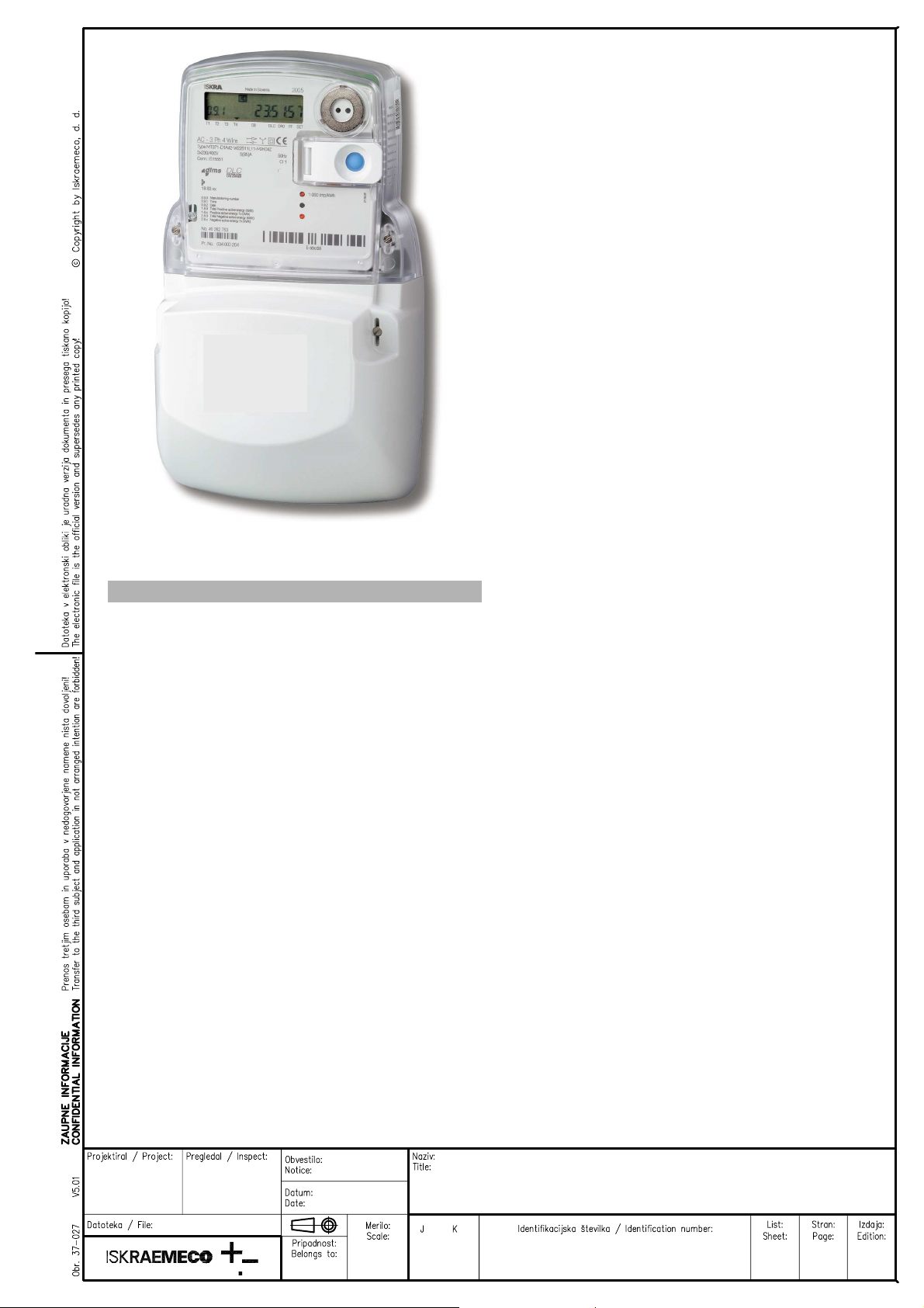
Meter appearance
(ME37y)
Fig. 3: Meter ME37y constituent parts
ITEM DESCRIPTION
1 Liquid crystal display (LCD)
2 Meter tehnical data
3 Legend for data displayed on LCD
4 A meter cover sealing screw
5 A terminal cover
6 A terminal cover sealing screw
7 Impulse LED
8 Scroll (blue) and Reset (orange) push-
buttons
9 IR optical interface
Two screws for fixing the meter cover (item 4) are
sealed with metrological seals.
The screw for fixing the terminal cover (item 6) and
the Reset push-button lid (item 8) are sealed with
seals of electric utility.
2.1 Meter case (ME37y)
A compact meter case consists of a meter base with
a terminal block and fixing elements for mounting the
meter, a meter cover and a terminal cover. The case
is made of self-distinguishing UV stabilized
polycarbonate which can be recycled. The case
ensures double insulation and IP54 (IEC 60529)
protection level against dust and water penetration.
The top hanger is provided on the back side of the
meter base, under the top edge. On request, an
extended top hanger can be mounted on the meter
base, which ensures the upper fixing hole height of
155 mm above the line connecting the bottom fixing
holes (DIN 43857).
The meter cover is made of transparent polycarbonate. A nickel-plated iron ring in the right top corner
is utilized for attaching an optical probe to the optical
port. There is a lid which is fixed to the meter cover
with a hinge. The lid covers the Reset push-button
and can be sealed in the closed position.
The terminal block contains current terminals,
auxiliary terminals and potential links for supplying
potential circuits of the meter.
Fig. 4: A terminal block of ME37y meter
ITEM DESCRIPTION
1 A switch for detection of terminal cover
opening
2 A screw for fitting current cables
3 Additional voltage terminals
4 Current terminals
5 Neutral terminals
6 Load control output
7 M-Bus communication interface
8 Second alarm input
9 First alarm input
Current terminals (item 4) are made of galvanized
iron sheet. They are universal terminals for all shapes
and cross sections of connected conductors up to
35 mm2. The terminals ensure the same contact
quality with conductors irrespective of whether they
are made of copper or aluminum. Only one screw in a
current terminal reduces time needed for the meter
installation in the field. Due to the indirect pressure on
the conductor it is not damaged.
Up to 8 auxiliary terminals can be fitted in the meter.
They can be utilized for M-Bus, bistable 6 A relay for
load control or alarm inputs. Inputs and outputs are
fitted into the meter regarding the customers request
at meter ordering.
Voltage terminals (item 3) are built into the meter
upon request. They are intended for supplying an
add-on unit from the meter terminal block.
Detectors of opening the terminal cover (item 1) and
the meter cover are built into the meter.
Mx37y
B0024445
KOMAR DOBERLET
5.6.2009
020611325_003_000_AD.doc
Mx37y TECHNICAL DESCRIPTION
Mx37y TEHNIČNI OPIS
LAD
020.611.325
10/45 3.
1994
-
2009
SD
detectioion
SD
detection
The terminal cover can be long or short. The meter
connection diagram is stuck on the internal side of
the terminal cover.
For single phase meters BS terminal block (I
max
=
100 A) is possible too.
2.2 Overall and fixing
dimensions (ME37y)
2.3 Meter configuration (ME37y)
SD
SD - Switching device
Fig. 6: ME371 meter block diagram
Fig. 5a: Overall and fixing dimensions of a meter fitted with
a long terminal cover
Fig. 5b: Overall and fixing dimensions of a meter fitted with
a short terminal cover
SD - Switching device
SD
GSM/GPRS MODEM
or
Rs485 COMMUNICATION INTER FACE
Fig. 7a: ME372 meter block diagram
Fig. 7b: ME374 meter block diagram
KOMAR DOBERLET
5.6.2009
020611325_003_000_AD.doc
Mx37y
B0024445
Mx37y TECHNICAL DESCRIPTION
Mx37y TEHNIČNI OPIS
LAD
020.611.325
11/45 3.

1994
-
2009
2.4 Metering system (ME37y)
Besides precision measurement of active, reactive,
apparent energy and demand in a wide metering and
temperature range, the metering system enables
measurement of phase voltages, currents and supply
quality.
One metering element is built in the meter. The
current sensor is shunt, while voltage sensor is
resistive voltage divider. Signals of currents and
voltages are fed to the A/D converters, and then they
are digitally multiplied so that instantaneous power is
calculated. The instantaneous powers are integrated
and summed in a microcontroller, as well as further
processed.
Mx37y
B0024445
KOMAR DOBERLET
5.6.2009
020611325_003_000_AD.doc
Mx37y TECHNICAL DESCRIPTION
Mx37y TEHNIČNI OPIS
LAD
020.611.325
12/45 3.
1994
-
2009
1
9
7
10
10
3.
Meter appearance
(MT37y)
3.1 MT371…
8
3.2 MT372…
1
2
4
2
5
3
4
6
5
6
3
7
8
1. Meter base 6. Scroll push-button
2. Meter cover
3. Fixing screw of meter
cover
4. LCD 9. Terminal cover
5. Optical port
Fig. 8: MT371 meter constituent parts
7. Cover of Reset pushbutton
8. LED
10. Fixing screw of
terminal cover
Two screws for fixing the meter cover (item 3) are
sealed with metrological seals.
Two screws for fixing the terminal cover (item 10) and
the Reset push-button lid are sealed with seals of
electric utility.
Fig. 9: MT372 meter constituent parts
1. LCD 8. A terminal cover
2. Technical data 9. A project number
3. Coupling circuit 10. A meter BAR code
4. A legend of registers
displayed on LCD
5. Meter cover sealing
screws
6. A meter serial number
7. Terminal cover sealing
screws
11. Impulse LEDs
12. Meter technical data
13. SCROLL and RESET
push-buttons
Two screws for fixing the meter cover (item 5) are
sealed with metrological seals.
Two screws for fixing the terminal cover (item 7) and
the Reset push-button lid are sealed with seals of
electric utility.
3.3 Meter case (MT37y)
A compact meter case consists of a meter base with
a terminal block and fixing elements for mounting the
meter, a meter cover and a terminal cover. The case
is made of self-extinguishing UV stabilized
polycarbonate which can be recycled. The case
ensures double insulation and IP54 (IEC 60529)
protection level against dust and water penetration.
The top hanger is provided on the back side of the
meter base, under the top edge. On request, an
extended metal top hanger can be mounted on the
meter base, which ensures the upper fixing hole
Mx37y
B0024445
KOMAR DOBERLET
5.6.2009
020611325_003_000_AD.doc
Mx37y TECHNICAL DESCRIPTION
Mx37y TEHNIČNI OPIS
LAD
020.611.325
13/45 3.
1994
-
2009
1
3
2
5
height of 230 mm above the line connecting the
bottom fixing holes (DIN 43857).
The meter cover is made of transparent
polycarbonate. A nickel-plated iron ring in the right
top corner is utilized for attaching an optical probe to
the optical port. There is a lid which is fixed to the
meter cover with a hinge. The lid covers the Reset
push-button and can be sealed in the closed position.
A terminal block complies with the DIN 43857
standard. It is made of high quality polycarbonate
assuring resistance to high temperatures, voltagebreakdown and mechanical strength.
Fig. 10: A terminal block of MT371 meter – bottom view
1. Current terminals
2. Auxiliary terminals
3. Voltage terminals for an
add-on unit
4. Detector of opening a
terminal cover
Fig. 11: A terminal block of MT372 meter – bottom view
1. Current terminals
2. Auxiliary terminals
3. Additional voltage
terminals
4. Detector of opening a
terminal cover
5. Auxiliary terminals –
inputs, outputs, SIM card
bed, alarm inputs, etc.
Current terminals (item 1) are made of zinc-plated
iron and have only one screw. A universal clamping
terminal assures the same quality of the contact
irrespective of the shape of the connection conductor
(a compact wire, a stranded wire, greater or smaller
cross-sections). It also assures faster meter
assembly. Available current terminals are:
• Current terminal according to DIN standard for
currents up to 85 A with 8.5 mm hole diameter
• Current terminal for currents up to 120 A with
9.5 mm hole diameter
• Current terminal for CT meters for currents up
to 6 A with 5.5 mm hole diameter
The meter can be equipped with max. four additional
voltage terminals (item 3): 2 (L1), 5 (L2), 8 (L3), 11
(N). They enable simple connection of additional
external devices.
KOMAR DOBERLET
5.6.2009
020611325_003_000_AD.doc
B0024445
Up to 6 auxiliary terminals (item 2) can be fitted in the
right side of the current terminals. They can be
utilized for M-Bus and OptoMOS relay impulse output
or OptoMOS relay control output. Instead of the
OptoMOS relay a 6 A bistable relay for load control
can be built into the meter. All of them are fitted into
the meter regarding the customer request at meter
ordering.
Versions:
- two pulse outputs (A+, R+) and relay (6 A) +
OptoMOS (100 mA)
- M-Bus and relay (6 A) + OptoMOS (100 mA)
Detectors (switches) of the terminal cover (item 4)
and the meter cover opening (on the PCB next to the
optical port) are built into the meter.
A sliding voltage bridge is intended for fast and
simple separation of meter current and voltage circuit
used for calibration or accuracy testing. A special
slider is built in each phase of the connection
4
terminal. It can be shifted up and down with a
screwdriver.
Position 0
Position 1
Sliding voltage bridge Auxiliary terminals
Fig. 12a: A terminal block – sliding voltage bridge and
auxiliary terminals
When a voltage bridge is in “0” position, it means that
the voltage part is separated from the current part.
During the meter testing and calibration the sliding
voltage bridges should be in position “0”.
When a voltage bridge is in position “1”, the voltage
part is not separated from the current part. During the
normal meter operation the potential links should be
closed (position “1”). Upon request, the potential links
can be built under the meter cover.
Mx37y TEHNIČNI OPIS
Mx37y TECHNICAL DESCRIPTION
Mx37y
LAD
020.611.325
14/45 3.
 Loading...