


Content
FPC 200
USER MANUAL
Mar 2017
Feeder F1 and F3
Motor M1 and M3
Busbar B2 and B3
Transformer T1 and T3
1 USER MANUAL FPC 200 - 3/2017

Content
This product complies with the Low Voltage Directive 2014/35/EU and EMC Directive 2014/30/EU. This
conformity has been proved by tests according to product standards IEC 60255-26 (for EMC directive)
and IEC 60255-27 (for Low Voltage Directive).
Preface
Copyright
Copyright © Iskra d.d. Ljubljana, Slovenia 2016. All rights reserved. Dissemination or reproduction of this document, or
evaluation and communication of its contents is not authorized except where expressly permitted.
Purpose of this manual
The manual describes the functionality, as well as operation, installation and commissioning instructions for the FPC 200
types F1, F3, M1, M3, B2, B3, T1 and T3.
Target audience
Protection engineers, mechatronic engineers, commissioning engineers, personnel concerned with setting, monitoring
and service of protection equipment, industrial automatic and control facilities and personnel of electrical facilities and
power plants.
Applicability
This manual is valid for all FPC 200 type multifunctional numerical relays.
Conformity
Liability statement
Specialists and responsible persons of Iskra d.d. has checked the contents of this manual to ensure the description of both
hardware and software are as accurate as possible. However, deviations from the description cannot be completely ruled
out, so that no liability can be accepted for any errors or failures contained in the given manual. The content of this
manual is reviewed regularly. Corrections will be included in following editions. Any suggested improvements are highly
appreciated. We reserve the right to make technical improvements without notice.
2 USER MANUAL FPC 200 - 3/2017

Content
Contact
If there are any questions or comments related to this document or product please contact us at:
Iskra d.d.
Stegne 21,
1000 Ljubljana
Slovenia – EU
Tel: +386 1 500 4282
Email: sales.energy@iskra.eu
Webpage: www.Iskra.eu/fpc200/
USER MANUAL FPC 200 - 3/2017 3

Content
Indicates an imminently hazardous
situation which, if not avoided, will result
in death, serious injury or property
damage.
Indicates a potentially hazardous situation
which, if not avoided, could result in death,
serious injury or property damage.
Indicates a potentially hazardous situation
which, if not avoided, could result in
minor or moderate injury of property
damage.
Indicates information about the device or
respective part of instruction manual
which is essential to highlight.
WARNING!
Risk of electrical shock!
CAUTION!
Refer to product technical documentation!
Protective and functional ground terminal.
Waste Electrical and Electronic Equipment (WEEE) Directive 2002/96/EC; the affixed
product label indicates that you must not discard this electrical / electronic product in a
domestic household waste.
Safety symbols and messages
The warnings and notes contained in this manual serve for your own safety as well as safety of people and property
around you. Please observe them!
The following indicators and standard definitions are used:
DANGER
WARNING
CAUTION
NOTE
Explanation of device safety symbols
Depending on the device layout, the following labels and symbols can be used on device itself or in the
corresponding technical documentation:
4 USER MANUAL FPC 200 - 3/2017

Content
QUALIFIED PERSONNEL
For the purpose of this manual and product, a qualified person is the one who is familiar with the
installation, construction and operation of the equipment and hazards involved. Following qualifications are
needed:
Knowledge to energize, de-energize, clear, ground and tag circuits and equipment in accordance
with established safety practices.
Knowledge of proper care and use of protective equipment in accordance with established safety
practices.
Proficiency in rendering first aid.
NOTE
This is a class A product. In a domestic environment this product may cause radio
interference in which case the user may be required to take adequate measures.
Warning
Only qualified personnel can work on this device. Certain parts of the device inevitably have dangerous voltage. Thorough
familiarity with all warnings and safety notices of this manual along with applicable safety regulations is required. Failure
to observe these precautions can result in fatality, personal injury or extensive material damage. The successful and safe
operation of this device is dependent on proper handling, installation, operation and maintenance by qualified personnel.
USER MANUAL FPC 200 - 3/2017 5

Content
Content
Preface ..................................................................................................................................................................................... 2
Copyright .............................................................................................................................................................................. 2
Purpose of this manual ........................................................................................................................................................ 2
Target audience ................................................................................................................................................................... 2
Applicability ......................................................................................................................................................................... 2
Conformity ........................................................................................................................................................................... 2
Liability statement ............................................................................................................................................................... 2
Contact ................................................................................................................................................................................. 3
Safety symbols and messages .............................................................................................................................................. 4
DANGER ........................................................................................................................................................................... 4
WARNING ........................................................................................................................................................................ 4
CAUTION .......................................................................................................................................................................... 4
NOTE ................................................................................................................................................................................ 4
Explanation of device safety symbols .............................................................................................................................. 4
Warning ............................................................................................................................................................................... 5
Content ..................................................................................................................................................................................... 6
1 Introduction ................................................................................................................................................................... 10
1.1 Presentation ......................................................................................................................................................... 11
1.2 Selection table ...................................................................................................................................................... 12
1.3 Device description ................................................................................................................................................ 13
Connection configuration ................................................................................................................................. 13
2 Functionality .................................................................................................................................................................. 14
2.1 Protections in general ........................................................................................................................................... 15
Default values ................................................................................................................................................... 15
Protection operation range .............................................................................................................................. 15
Time characteristics .......................................................................................................................................... 17
2.2 Current based protections .................................................................................................................................... 20
Overcurrent protection - ANSI code 50/51 ...................................................................................................... 20
Earth fault overcurrent protection - ANSI code 50/51|N/G ............................................................................. 22
Negative sequence/unbalance overcurrent protection - ANSI code 46 ........................................................... 24
Restricted earth fault protection - ANSI code 64REF ....................................................................................... 26
Phase undercurrent protection - ANSI code 37 ................................................................................................ 28
Inrush restraint ................................................................................................................................................. 30
6 USER MANUAL FPC 200 - 3/2017

Content
2.3 Voltage based protections .................................................................................................................................... 32
Phase to phase overvoltage protection - ANSI code 59 .................................................................................... 32
Neutral voltage displacement - ANSI code 59N ................................................................................................ 34
Phase to phase undervoltage protection - ANSI code 27 ................................................................................. 36
Positive sequence undervoltage protection - ANSI code 27D .......................................................................... 38
Remanent undervoltage protection - ANSI code 27R ....................................................................................... 40
2.4 Frequency based protections ................................................................................................................................ 42
Overfrequency protection - ANSI code 81H ..................................................................................................... 42
Underfrequency protection - ANSI code 81L .................................................................................................... 44
Rate of change of frequency protection - ANSI code 81R ................................................................................ 46
2.5 Power and machine protections ........................................................................................................................... 48
Thermal overload protection – ANSI code 49T ................................................................................................. 48
Machine Thermal Overload Protection - ANSI code 49M ................................................................................. 50
Temperature monitoring - ANSI code 38/49T .................................................................................................. 53
Locked rotor protection, excessive starting time - ANSI code 48/51LR/14 ...................................................... 55
Starts per hour - ANSI code 66 .......................................................................................................................... 57
Buchholz relay protection – ANSI code 63 ........................................................................................................ 58
Thermal switch protection – ANSI code 26 ....................................................................................................... 59
2.6 Automation and diagnostic ................................................................................................................................... 60
Circuit breaker control and monitoring - ANSI 94/69 with integrated circuit breaker failure - ANSI 50BF/62BF
function. ......................................................................................................................................................................... 60
Trip circuit supervision - ANSI 74 - TCS ............................................................................................................. 66
Auto-reclosing function - ANSI 79 - AR ............................................................................................................. 69
Machine control ................................................................................................................................................ 72
External trip – EXT-T ......................................................................................................................................... 74
2.7 User defined signals .............................................................................................................................................. 75
Description ........................................................................................................................................................ 75
Assigning user defined signals to digital outputs .............................................................................................. 75
Blocking of individual protection ...................................................................................................................... 75
2.8 Disturbance recording ........................................................................................................................................... 76
Description ........................................................................................................................................................ 76
USB stick ........................................................................................................................................................... 76
Trigger ............................................................................................................................................................... 76
Recorded data ................................................................................................................................................... 76
Clearing disturbance records ............................................................................................................................ 76
Setting parameters ........................................................................................................................................... 77
2.9 Measurements ...................................................................................................................................................... 78
Presented measured values .............................................................................................................................. 78
USER MANUAL FPC 200 - 3/2017 7
Content
Nominal values ................................................................................................................................................. 78
Current measurement ...................................................................................................................................... 78
Voltage measurement ...................................................................................................................................... 78
Frequency measurement ................................................................................................................................. 78
Symmetrical components ................................................................................................................................. 79
Temperature ..................................................................................................................................................... 79
2.10 Self-diagnostic ....................................................................................................................................................... 80
System status register .................................................................................................................................. 80
Operating states ........................................................................................................................................... 80
Internal faults description ............................................................................................................................ 81
3 Communication ............................................................................................................................................................. 82
3.1 Modbus RTU ......................................................................................................................................................... 82
General description .......................................................................................................................................... 82
Modbus PDU (protocol data unit) .................................................................................................................... 82
Modbus function supported ............................................................................................................................. 82
Time synchronization ....................................................................................................................................... 82
Events ............................................................................................................................................................... 83
Parameters ....................................................................................................................................................... 84
Address table .................................................................................................................................................... 85
3.2 Protocol IEC60870-5-103 ...................................................................................................................................... 98
General description .......................................................................................................................................... 98
Acronyms and Terms ........................................................................................................................................ 98
Protocol data transfer ...................................................................................................................................... 98
Supported standard options and functions .................................................................................................... 100
8 Interoperability ......................................................................................................................................................... 100
Parameters ..................................................................................................................................................... 107
Data table – Monitor direction ....................................................................................................................... 108
Data table – Control direction ........................................................................................................................ 111
4 Settings ........................................................................................................................................................................ 112
4.1 Introduction ........................................................................................................................................................ 113
4.2 Human machine interface (HMI) ........................................................................................................................ 113
User interface ................................................................................................................................................. 113
LCD .................................................................................................................................................................. 114
Menu overview ............................................................................................................................................... 116
Submenus overview ....................................................................................................................................... 119
4.3 PC based graphical interface MiQen Setting Studio ........................................................................................... 130
Installation ...................................................................................................................................................... 131
Using MiQen software .................................................................................................................................... 132
8 USER MANUAL FPC 200 - 3/2017

Content
5 Mounting and commissioning ..................................................................................................................................... 148
5.1 Safety instructions ............................................................................................................................................... 149
5.2 Precautions ......................................................................................................................................................... 149
Device stored in its original packaging ............................................................................................................ 149
Device installed in a cubicle ............................................................................................................................ 150
Working environment ..................................................................................................................................... 150
5.3 Equipment identification and unpacking ............................................................................................................ 151
Package specification ...................................................................................................................................... 151
Device identification ....................................................................................................................................... 151
5.4 Device installation ............................................................................................................................................... 152
Service conditions ........................................................................................................................................... 152
Dimensions ..................................................................................................................................................... 152
Cut-out dimensions ......................................................................................................................................... 153
Assembly ......................................................................................................................................................... 154
Spacing ............................................................................................................................................................ 155
Recommended external protection elements ................................................................................................ 155
5.5 Connection .......................................................................................................................................................... 156
Grounding wire ............................................................................................................................................... 157
Connection scheme ........................................................................................................................................ 158
Serial connection ............................................................................................................................................ 159
5.6 External module .................................................................................................................................................. 160
EX 408 Temperature module .......................................................................................................................... 160
5.7 Commissioning .................................................................................................................................................... 162
Handling conditions ........................................................................................................................................ 162
Testing equipment required ........................................................................................................................... 162
Device overall check ....................................................................................................................................... 162
Checking parameter and protection setting ................................................................................................... 163
Start-up ........................................................................................................................................................... 163
Hardware overview ......................................................................................................................................... 163
Protection validation ...................................................................................................................................... 166
6 Technical data .............................................................................................................................................................. 167
6.1 Type tests ............................................................................................................................................................ 168
6.2 Technical characteristics ..................................................................................................................................... 170
7 Appendix A: Ordering code .......................................................................................................................................... 173
8 Appendix B: Analog inputs configuration .................................................................................................................... 174
9 Glossary ........................................................................................................................................................................ 175
USER MANUAL FPC 200 - 3/2017 9

Introduction
1 Introduction
The chapter introduces FPC 200 device. Provided information can help you to pick device type which covers specific needs
of your project.
1.1 Presentation ........................................................................................................................................................... 8
1.2 Selection table ........................................................................................................................................................ 9
1.3 Device description ................................................................................................................................................ 10
10 USER MANUAL FPC 200 - 3/2017

Introduction
1.1 Presentation
FPC 200 is a family of current and voltage numerical protection relays with easy to use interface meant for variety of
solutions in industry and power distribution.
Its robust design enables it to be placed in demanding industrial environments.
Setting can be done completely through user friendly Human Machine Interface (HMI) unit. Visual experience is enhanced
through PC based interface software MiQen featuring specially designed menus where electrical attributes of power
system are graphically and numerically displayed in real time.
Transferring settings between different devices is easily done thanks to front panel USB port. Same settings are
transferred from one device to another using USB stick which can also be used to save fault recordings, counters and
software updates.
FPC 200 is a member of NEO3000 Substation system and can be integrated to any other new or existing substation or
automation protection and control system.
Figure 1.1: FPC 200 protection relay.
Main features are:
- Robust design for industrial usage
- Fast and simple commissioning
- Fault and event recording
- Intuitive user interface
- Multiple communication capabilities
- Numerical and graphical MiQen software tool
- Easy data transfer using USB stick
- Low power consumption
USER MANUAL FPC 200 - 3/2017 11

Introduction
Feeder
Busbar
Motor
Transformer
ANSI code
F1
F3
B2
B3
M1
M3
T1
T3
Current protections
Overcurrent DT/IDMT with Inrush restraint and Cold
Load Pick-up
50/51
4 4 4 4 4
4
Earth fault overcurrent DT/IDMT with Inrush restraint
and Cold Load Pick-up
50/51|N/G
4 4 4 4 4
4
Restricted earth-fault
64REF
2 2 2
Negative sequence overcurrent / unbalance
46 1 1 1 1 1 1
Phase undercurrent
37 1 1
Voltage protections
Phase-to-phase under voltage
27
2 2
Remanent under voltage
27R
1 1 Positive sequence under voltage
27D
2 2
Phase-to-phase overvoltage
59 2 2
Neutral voltage displacement/Residual overvoltage
59N 2 2
Over frequency
81H 2 2
Under frequency
81L 2 2
Rate of change (ROCOF)
81R 1
Power and machine protections and diagnostic
3 phase thermal overload (transformers)
49
Temperature monitoring (up to 8 sensors)
38/49T
Locked rotor, excessive starting time
48/51LR/14
Starts per hour
66
Thermostat / Buchholz switch
26/63
External trip
2 2 2 2 2 2 2
2
Automation and diagnostic
Circuit breaker control and monitoring
94/69
Circuit breaker failure
50BF/62BF
Trip circuit supervision (TCS)
74TC
Auto-reclosing
79
Lockout Relay
86LR/94
Cumulative breaking current
Metering
Phase current, RMS, THD, Harm., Residual c. 3I0
Earth current sensitive
Opt.
Opt.
Opt.
Opt.
Opt.
Opt.
Ph. & PPV voltages, RMS, THD, Harmonics
Frequency
Running hours
Communication protocols
Modbus
Optional
IEC 60870-5-103
Optional
1.2 Selection table
Table 1: Selection table Opt. Optional, included.
12 USER MANUAL FPC 200 - 3/2017

Introduction
1.3 Device description
Design of FPC 200 is modular. Base unit consists of housing, human machine interface (HMI), analog measurement card
(AMC) and six digital outputs (DO) with power supply (PS). AMC provides current or voltage measurements. Optional cards
extends the input/output and communication capabilities. Further extension is possible with external modules.
Base unit with maximum configuration includes:
Front panel with HMI and USB interface
rear panel with 10 digital inputs
8 digital outputs
2 serial communication ports
3 analog outputs
4 analog inputs
Connection configuration
Two connection configurations exist based on device type. Current measuring configuration is shown on Figure 1.2
whereas voltage version is shown on Figure 1.3.
Figure 1.2: Current measurements configuration.
Figure 1.3: Voltage measurements configuration.
USER MANUAL FPC 200 - 3/2017 13

Functionality
2 Functionality
This chapter describes various functions of the FPC 200 device. It explains options of each function in maximum
configuration and provides information on how to determine the setting values and, if required, corresponding formulas.
The following information also allows you to specify which of the available functions to use.
2.1 Protections in general ........................................................................................................................................... 15
2.2 Current based protections .................................................................................................................................... 20
2.3 Voltage based protections .................................................................................................................................... 32
2.4 Frequency based protections ............................................................................................................................... 42
2.5 Power and machine protections ........................................................................................................................... 48
2.6 Automation and diagnostic ................................................................................................................................... 60
2.7 User defined signals .............................................................................................................................................. 75
2.8 Disturbance recording .......................................................................................................................................... 76
2.9 Measurements ...................................................................................................................................................... 78
2.10 Self-diagnostic ....................................................................................................................................................... 80
3 Communication ............................................................................................................................................................. 82
3.1 Modbus RTU ......................................................................................................................................................... 82
14 USER MANUAL FPC 200 - 3/2017

Functionality
Parameter
Range
Pickup delay
0 … 5 … 1000 ms
Minimum value of pickup delay is 0 ms, maximum
value is 1000 ms. Default value is set to 5 ms.
Pickup value
Drop-out value
Fault detection
Monitored value
Fault area
Pickup signal
Fault detection
Trip signal
Pickup
delay
Trip delay
Drop-out
delay
Drop-out
delay
Fault
detection
Pickup
Blocking
Pickup
Delay
Pickup
&
2.1 Protections in general
Within this chapter the general theory of protection functions is described. For clear understanding several time
characteristics for different scenarios are presented.
Default values
Default values are presented as bold.
Example:
Table 2 Example of default parameter setting.
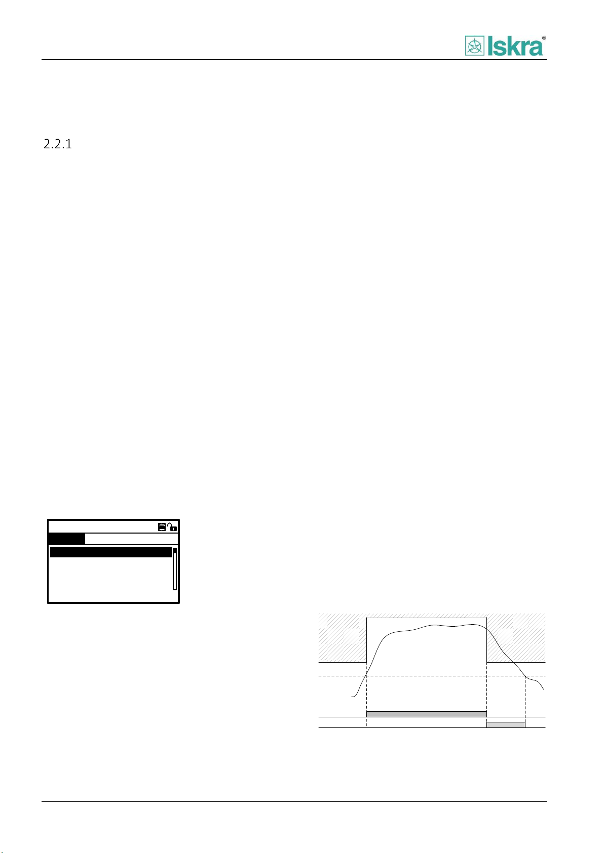
Protection operation range
Fault is detected when monitored value exceeds the
chosen threshold (pickup value). At that point the
protection enters into protection operation range or
fault area. To prevent unwanted switching a hysteresis
characteristic is introduced. Drop-out value is set
relative to pickup value.
When the monitored value enters the protection
operating range the protections picks up. On the other
hand when the value falls below the operating range the
protection drops or resets.
Protection operation range is shown on Figure 2.1.
short period of time. It is usually used when very long
time characteristics are used. In case the protection
trips, drop out delay is not accounted for and other
means of delaying trip signal are used.
Figure 2.2: Pickup signal and Trip signal when fault duration is
shorter than trip delay.
2.1.2.1 Pickup logic
The pickup signal indicates that monitored value
exceeded the set value and indicates that a fault
occurred (Figure 2.2). The pickup delay is intended for
fault signalling stabilization to prevent the short-lived
disturbances in the measuring part of the system from
being reported as faults (Figure 2.4).
Figure 2.1: Protection operation range - fault area.
Example: Nominal current of protected element I
set to 300 A, pickup value is set to 1,1 I
is 0,95 Ip. The protection will pick up when current
exceeds 330 A. It will drop out when the current drops
below 313,5 A.
Operational scenario is illustrated on Figure 2.2. Dropout delay prevents the timer of protection function to
reset in case the fault falls below the pickup value for a
USER MANUAL FPC 200 - 3/2017 15
and Drop-out
n_obj
n_obj
is
The pickup is set (Figure 2.3):
When a fault is detected and
Pickup delay confirmation time runs out and
There is no blocking
Figure 2.3: Pickup set logic.

Functionality
Pickup signal
Fault detection
Trip signal
Drop-out
delay
Pickup
delay
Pickup
delay
Trip
delay
Trip
Delay
&
Blocking
Pickup
Fault
detection
Trip
Pickup
Pickup block
Fault
Pickup blocked
Pickup
delay
Pickup
delay
Trip
delay
Trip
Trip
delay
Pickup drops when:
Fault is not present anymore, the drop-out
delay runs out and the Trip signal has not set
yet or
fault is not present anymore and Trip signal is
already set or
a blocking occurs.
Figure 2.4: Fault confirmation.
2.1.2.2 Trip logic
The Trip signal is intended for opening of circuit breaker,
which eliminates faulty element from power system.
Majority of faults have transient character and
disappear spontaneously. The duration of such faults is
relatively short. In order to avoid unnecessary opening
of circuit breaker the Trip signal can be delayed. Among
others the delaying of Trip signal may be used to ensure
selectivity along the power system network. The delay is
set with Trip delay parameter. In case the protection is
blocked the Trip signal will not set.
The Trip is set (Figure 2.5):
When a fault is detected and
when the pickup signal is stated and
trip delay time runs out and
no blocking is present.
Figure 2.5: Trip set logic.
Trip signal drops:
when the pickup drops or Blocking appears
When the protection trips there are some particular
delays on detection and trip execution levels. Several
milliseconds can pass during transfer of the signal to
external output relay and forward to the circuit breaker
switch of the circuit. The compensation of lost time is
solved with default value.
2.1.2.3 Blocking
Function is blocked when any pickup Block input is set. It can be set through digital input port or it can be set internally in
combination with different functions. When the protection is blocked the pickup signal drops and pickup blocked signal is
stated. Consequently after the pickup signal drops the Trip delay timer resets. After the blocking is reset and if the fault is
still present the protection function starts again. Protection operation with blocking signal turned on for a certain amount
of time is shown on Figure 2.6.
Figure 2.6: Protection operation with blocking signal turned on for a certain duration.
16 USER MANUAL FPC 200 - 3/2017

Functionality
0 1,0
drop
out
20 x Pickup
Trip
delay
Fault area
Fault
amplitude
1,1
Name of curve
IEC Normal inverse
IEC Very inverse
IEC Extremely inverse
IEC Long time inverse
IEEE Moderately inverse
IEEE Very inverse
IEEE Extremely inverse
RI curve
Name of characteristic
α
β
Normal inverse
0,02
0,14
Very inverse
1
13.5
Extremely inverse
2
80
Long time inverse
1
120
Name of characteristic
α
β
Moderately inverse
0,02
0,114
0,0515
Very inverse
2
0,491
19,61
Extremely inverse
2
0,1217
28,2
T …
protection trip time
k …
IDMT coefficient factor
α, β, …
Coefficient values
I …
Fault current amplitude
…
set limit of fault range, pickup value
Time characteristics
The main purpose of inverse time characteristics (IDMT
– Inverse Definite Minimum Time) is to enable shorter
time of protection trip when the fault current amplitude
is greater. At a set fault value the protection must trip in
time that can be read out from a characteristic. The
operation time depends on the measured current value
in accordance with standards IEC 60255-3 and IEEE C-
37112.
The available area of inverse time characteristic is
defined in a range between 1,1 and 20 Ip, where Ip
stands for pickup value. Amplitudes above 20 Ip have an
equal trip delay as the amplitude at 20 Ip. Amplitudes
from 1,1 Ip and lower have an equal trip delay as the
amplitude at 1,1 Ip.
The type of time characteristic can be chosen with the
mode parameter. It is necessary to set the pickup value
and IDMT coefficient parameters. Values are used with
all types of time characteristics. The IDMT coefficient
factor defines the time delay level. Lower values
indicate faster operation at equal fault values.
The fault current amplitude is not always constant and
can change during fault duration. For this reason the
algorithm dynamically integrates parts of time during
the fault according to particular characteristic and when
the sum reaches the switch off limit the protection trips.
2.1.3.1 IEC characteristics
Equation 1 Time to trip for IEC inverse characteristics.
Table 4: Coefficients of IEC characteristics.
2.1.3.2 RI curve
Equation 2 Time to trip for RI inverse characteristics.
2.1.3.3 IEEE characteristics
Equation 3 Time to trip for IEEE inverse characteristics
equation.
Figure 2.7: Time inverse characteristic.
Table 3 Time inverse curve types.
Table 5: Coefficients of IEEE characteristics.
USER MANUAL FPC 200 - 3/2017 17
Functionality
1.1 2 3 4 5 6 7 8 9 10
1
10
100
1000
1500
IEC Normal inverse
I / In
t [s]
0.05
IDMT
0.1
IDMT
0.2
IDMT
0.3
IDMT
0.4
IDMT
0.6
IDMT
0.8
IDMT
1
IDMT
1.1 2 3 4 5 6 7 8 9 10
0.1
1
10
100
1000
1500
IEC Very inverse
I / In
t [s]
0.05
IDMT
0.1
IDMT
0.2
IDMT
0.3
IDMT
0.4
IDMT
0.6
IDMT
0.8
IDMT
1
IDMT
1.1 2 3 4 5 6 7 8 9 10
0.1
1
10
100
1000
1500
IEC Extremely inverse
I / In
t [s]
0.05
IDMT
0.1
IDMT
0.2
IDMT
0.3
IDMT
0.4
IDMT
0.6
IDMT
0.8
IDMT
1
IDMT
1.1 2 3 4 5 6 7 8 9 10
1
10
100
1000
1500
IEC Long time inverse
I / In
t [s]
0.05
IDMT
0.1
IDMT
0.2
IDMT
0.3
IDMT
0.4
IDMT
0.6
IDMT
0.8
IDMT
1
IDMT
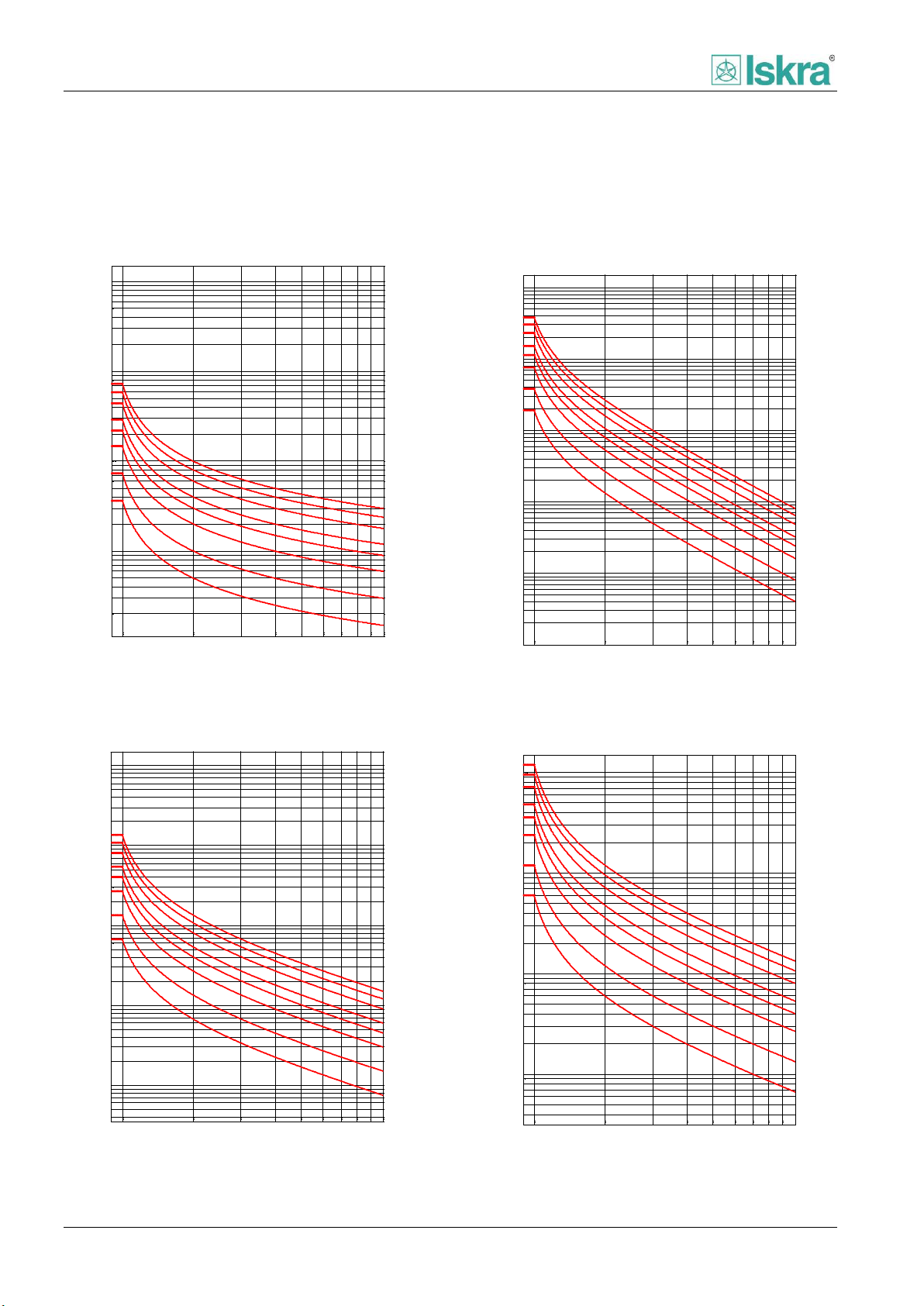
2.1.3.4 Graphs of inverse characteristics
Graphs below represent time to trip depending on current and user defined IDMT setting for each of the inverse time
characteristics.
Figure 8 IEC Normal inverse characteristics.
Figure 9 IEC Very inverse characteristics.
18 USER MANUAL FPC 200 - 3/2017
Figure 10IEC Extremely inverse characteristics.
Figure 11 IEC Long time inverse characteristics.

Functionality
1.1 2 3 4 5 6 7 8 9 10
0.1
1
10
100
150
IEEE MI
I / In
t [s]
0.05
IDMT
0.1
IDMT
0.2
IDMT
0.3
IDMT
0.4
IDMT
0.6
IDMT
0.8
IDMT
1
IDMT
1.1 2 3 4 5 6 7 8 9 10
0.1
1
10
100
150
IEEE EI
I / In
t [s]
0.05
IDMT
0.1
IDMT
0.2
IDMT
0.3
IDMT
0.4
IDMT
0.6
IDMT
0.8
IDMT
1
IDMT
1.1 2 3 4 5 6 7 8 9 10
0.1
1
10
100
150
IEEE VI
I / In
t [s]
0.05
IDMT
0.1
IDMT
0.2
IDMT
0.3
IDMT
0.4
IDMT
0.6
IDMT
0.8
IDMT
1
IDMT
1.1 2 3 4 5 6 7 8 9 10
1
10
100
150
RI
I / In
t [s]
0.05
IDMT
0.1
IDMT
0.2
IDMT
0.3
IDMT
0.4
IDMT
0.6
IDMT
0.8
IDMT
1
IDMT
Figure 12 IEEE moderately inverse characteristics.
Figure 13 IEEE Extremely inverse characteristics.
USER MANUAL FPC 200 - 3/2017 19
Figure 14 IEEE Very inverse characteristics.
Figure 15 RI inverse time characteristics.
Functionality
50/51 Over current
Mode:
Enable:
IDMT coeficient:
0,02
ON
Pickup value: 1,2xIn
A
Trip delay: 0,4s
Ext. inverse
1A 1B 2A 2B 3A 3B 4A
Pickup value
Drop-out value
CLP activated
Monitored value
Fault area
Fault detection
2.2 Current based protections
Overcurrent protection - ANSI code 50/51
Overcurrent protection is one of the basic functions of FPC 200 numerical relays. It protects the feeder or other elements
of the power system from overcurrent when fault occurs. It comprises of various time-delayed characteristics. Protective
function includes Inrush restraint [2.2.5] and Cold load pickup (CLP) protection.
2.2.1.1 Functionality
Overcurrent protection is used as non-directional time
delayed overcurrent and short-circuit protection. It picks
up when current in one, two or three phases exceeds
the set threshold. The function can be enabled or
disabled through corresponding menu. The trip time
characteristics can be selected to be Instantaneous,
definite time (DT) or inverse definite minimum time
(IDMT). When instantaneous operation mode is selected
the trip signal is stated as the DT characteristic. The
settings of this function are applied to each of the three
phases to produce pickup and trip signals per each
phase.
Several overcurrent protection instances with different
settings can run independently at the same time.
The selection of pickup value, pickup delay as well as
drop-out ratio and drop-out delay helps the user to fine
tune the protection according to the project
specifications.
2.2.1.3 Delays
Function includes following delays explained in Chapter
2.1:
Pickup delay
Trip delay
Drop-out delay
2.2.1.4 Cold load pickup
A temporary increased starting current can appear
when energizing feeders with loads that had a long zero
voltage period (e.g. air-conditioning systems, heating
installations, motors...). Its value can be up to several
times higher than the nominal current. To avoid
unwanted protection operation the pickup limit has to
be raised temporarily. The function is set with
parameter Enable. It triggers through the activation of
corresponding digital input or when current raises
above
5 % of I
of time has passed.
in at least one phase after certain amount
n_obj
Figure 2.16: Overcurrent protection setting.
2.2.1.2 Measurements
The value of each phase current is acquired through
separate input current transformer. The measured
phase currents are compared with the set pickup value.
20 USER MANUAL FPC 200 - 3/2017
The dynamic pickup value changeover is common to all
overcurrent elements. With inverse characteristics, the
CLP influences only the fault detection limit, whereas
the time calculation of the selected inverse
characteristic is not affected.
Figure 2.17: Operation with CLP activated for a shorter than
fault time duration.

Functionality
Parameter
Range
Description
Enabled
No
Yes
Enabling protection function.
Operate mode
Instantaneous
Definite time
IEC Normal inverse
IEC Very inverse
IEC Extremely inverse
IEC Long-time inverse
IEEE Moderately inverse
IEEE Very inverse
IEEE Extremely inverse
RI
Protection operation mode:
Definite time – constant time of operation
Inverse characteristics – selected IDMT characteristic
IDMT coefficient
0,05 … 1,00
Coefficient of selected IDMT characteristic
Pickup value
0,05 … 1,00 … 40,00 I
n_obj
Limit of monitored current.
Trip delay
0,00 ... 0,50 … 300,00 s
Delay of trip signal
Inrush restraint source
None
Inrush-1
Inrush-2
Input source of Inrush restraint [Chapter 2.2.5] blocking function.
Pickup delay
0 … 5,00 … 1000 ms
Time stabilization of fault detection. As a filter of short
disturbances on measuring circuits. Time before protection starts.
Drop-out delay
0,00 … 0,20 … 60,00 s
Time stabilization of pickup signal. Time when the monitored value
is outside the operating range, but the protection does not stop
yet.
Drop-out ratio
0,80 … 0,95 … 1,00 Ip
Drop-out value below which the protection drops.
Cold load pickup Enabled
No
Yes
Enabling CLP function.
Cold load pickup Level
1,01 … 1,50 … 10,00 Ip
Pickup and drop-out value increase.
Cold load pickup Duration
0 … 60 … 3600 s
Pickup value increase duration time.
Pickup block
None
Variable 1
Variable 2
Variable 3
Variable 4
Source of blocking signal.
Name
Description
Pickup
Total consecutive number of pickup signals.
Trip
Consecutive number of trip signals.
Pickup L1
Consecutive number of pickup signals detected in phase L1
Pickup L2
Consecutive number of pickup signals detected in phase L2
Pickup L3
Consecutive number of pickup signals detected in phase L3
CLP
Consecutive number of cold load pickup
2.2.1.5 Setting parameters
Table 6: Overcurrent protection function parameters.
2.2.1.6 Counters
Table 7: Counters presented in overcurrent protection.
21 USER MANUAL FPC 200 - 3/2017

Functionality
50N/51N Ground prot
Mode:
Enable:
IDMT coeficient:
0,02
ON
Pickup value: 1,2xIn
A
Trip delay: 0,4s
Ext. inverse
1A 1B 2A 2B 3A 3B 4A
Pickup value
Drop-out value
CLP activated
Monitored value
Fault area
Fault detection
Earth fault overcurrent protection - ANSI code 50/51|N/G
Earth fault overcurrent protection is one of the basic functions of FPC 200 numerical relay. It comprises of various timedelayed characteristics. Protective function includes CLP and inhibition by Inrush restraint [2.2.5] function.
2.2.2.1 Functionality
Earth fault overcurrent function is used as nondirectional earth fault protection. Pickup value of this
function is normally set lower than pickup value of
phase overcurrent protection. Protection picks up when
the earth fault current exceeds the set threshold value.
The function can be enabled or disabled through
corresponding menu. Trip time characteristics can be
selected to be Instantaneous, Definite time (DT) or
Inverse definite minimum time (IDMT). When
instantaneous operation mode is selected the trip signal
is stated as the DT characteristic.
Several earth fault protection instances with different
settings can run independently at the same time.
The selection of pickup value, pickup delay as well as
drop-out ratio and drop-out delay helps the user to fine
tune the protection according to the project
specifications.
2.2.2.3 Delays
Function includes following delays explained in Chapter
2.1:
Pickup delay
Trip delay
Drop-out delay
2.2.2.4 Cold load pickup
A temporary increased starting current can appear
when energizing feeder loads that had a long zero
voltage period (e.g. air-conditioning systems, heating
installations, motors...). Its value can be up to several
times higher than the nominal current. To avoid
unwanted protection operation the pickup limit has to
be raised temporarily. The function is set with
parameter Enable. It triggers only when CB Close
command is executed manually.
Figure 2.18: Earth fault overcurrent setting.
2.2.2.2 Measurements
Earth fault current is acquired directly through analog
measurement or calculated.
Sensitive current input can be selected for direct earth
fault measurement. When sensitive analog input Ie is
not present earth current 3I0 is calculated using phase
currents analog measurements.
The dynamic pickup value changeover is common to all
overcurrent elements. With inverse characteristics, the
CLP influences only the fault detection limit, whereas
the time calculation of the selected inverse
characteristic is not affected.
Figure 2.19: Operation with CLP activated for a shorter than
fault time duration.
22 USER MANUAL FPC 200 - 3/2017

Functionality
Parameter
Range
Description
Enabled
No
Yes
Enabling protection function.
Operate mode
Instantaneous
Definite time
IEC Normal inverse
IEC Very inverse
IEC Extremely inverse
IEC Long-time inverse
IEEE Moderately inverse
IEEE Very inverse
IEEE Extremely inverse
RI
Protection operation mode:
Definite time – constant time of operation
Inverse characteristics – selected IDMT characteristic
Pickup value
0,005 … 0,10 … 1,25 I
n_e
Limit of monitored current.
Trip delay
0,00 … 2,00 … 300,00 s
Delay of trip signal
IDMT coefficient
0,05 … 1,00
Coefficient of selected IDMT characteristic
Inrush restraint source
None
Inrush-1
Inrush-2
Input source of Inrush restraint [Chapter 2.2.5] blocking
function.
Pickup delay
0 … 5,00 … 1000 ms
Time stabilization of fault detection. As a filter of short
disturbances on measuring circuits. Time before protection
starts.
Drop-out delay
0,00 … 0,20 … 60,00 s
Time stabilization of pickup signal. Time when the monitored
value is outside the operating range, but the protection does
not stop yet.
Drop-out ratio
0,80 … 0,95 … 1,00 Ip
Drop-out value below which the protection drops.
Input current
3I0
Ie
Selector for protection to account for calculated residual
current (3I0) for 50N/51N function or measured residual
current (Ie) for 50G/51G function.
Cold load pickup Enabled
No
Yes
Enabling CLP function.
Cold load pickup Level
1,01 … 1,50 … 10,00 Ip
Pickup and drop-out value increase.
Cold load pickup Duration
0 … 60 … 3600 s
Pickup value increase duration time.
Pickup block
None
Variable 1
Variable 2
Variable 3
Variable 4
Source of blocking signal.
Name
Description
Pickup
Total consecutive number of pickup signals.
Trip
Consecutive number of trip signals.
CLP
Consecutive number of cold load pickup
2.2.2.5 Setting parameters
Table 8: Earth fault overcurrent protection function parameters.
2.2.2.6 Counters
Table 9: Counters presented in earth fault overcurrent protection.
USER MANUAL FPC 200 - 3/2017 23

Functionality
Definite time
46 Negative sequence
Mode:
Enabled:
IDMT coeficient:
0.05
Yes
Pickup value: 0.1In
Trip delay: 1.5s
A B
Negative sequence/unbalance overcurrent protection - ANSI code 46
Uneven distribution of currents is caused by asymmetrical loads, single or two phase earth faults, line disconnections or
irregular switching operations. Negative sequence/unbalance overcurrent protection function calculates negative
sequence current of symmetrical components in three phase system.
2.2.3.1 Functionality
Function is used for detecting unbalanced loads in the
power system. Negative sequence value is defined by
the asymmetry of power system. Asymmetrical faults
selectivity is achieved by considering negative sequence
value.
In order to prevent malfunction of the protection and to
achieve better selectivity additional operational
conditions must be applied:
All phase currents have to be below the set
Maximum current value and
At least one phase current has to be above the
set Minimum current value
Protection selectivity is further improved with trip delay
time value set higher than the one set in main
protections (e.g. Overcurrent protection).
The trip time characteristics can be selected to be
Instantaneous, definite time (DT) or inverse definite
minimum time (IDMT). When instantaneous operation
mode is selected the trip signal is stated as the DT
characteristic with zero trip delay parameter.
The selection of pickup value, pickup delay as well as
drop-out ratio and drop-out delay helps the user to fine
tune the protection according to the project
specifications.
Figure 2.20 Example of parameter settings on HMI.
2.2.3.2 Delays
Function includes following delays explained in Chapter
2.1:
Pickup delay
Trip delay
Drop-out delay
24 USER MANUAL FPC 200 - 3/2017

Functionality
Parameter
Range
Description
Enabled
No
Yes
Enabling protection function.
Operate mode
Instantaneous
Definite time
IEC Normal inverse
IEC Very inverse
IEC Extremely inverse
IEC Long-time inverse
IEEE Moderately inverse
IEEE Very inverse
IEEE Extremely inverse
RI
Protection operation mode:
Definite time – constant time of operation
Inverse characteristics – selected IDMT characteristic
IDMT coefficient
0,05 … 1,00
Coefficient of selected IDMT characteristic
Pickup value
0,01 … 0,10 … 3,00 I
n_obj
Limit of monitored current.
Trip delay
0,00 … 1,50 … 300,00 s
Delay of trip signal.
Pickup delay
0 … 5,00 … 1000 ms
Time stabilization of fault detection. As a filter of short disturbances on
measuring circuits. Time before protection starts.
Drop-out delay
0,00 … 0,20 … 60,00 s
Time stabilization of pickup signal. Time when the monitored value is
outside the operating range, but the protection does not stop yet.
Drop-out ratio
0,80 … 0,95 … 1,00 Ip
Drop-out value below which the protection drops.
Pickup block
None
Variable 1
Variable 2
Variable 3
Variable 4
Source of blocking signal.
Minimal current
0,01 … 0,10 … 2,00 I
n_obj
Minimal current above which the protection operates. Protection is
blocked if all phase currents are below the set value.
Maximum current
0,10 … 4,00 … 10,00 I
n_obj
Maximum current below which the protection still operates. Protection is
blocked if any of the phase currents is above the set value.
Name
Description
Pickup
Total consecutive number of pickup signals.
Trip
Consecutive number of trip signals.
2.2.3.3 Setting parameters
Table 10: Negative/unbalance sequence protection function parameters.
2.2.3.4 Counters
Table 11: Counters presented in negative sequence protection.
USER MANUAL FPC 200 - 3/2017 25
Functionality
Off
64 Res. Earth fault
Mode:
Enabled:
Pickup value:
0.1In
Yes
Trip delay: 2s
A
1A 1B 2A 2B
CONTROL SETTINGS
L1
L2
L3
3Io=I1+I2+I3
FPC 200
Ie
I1I2I3
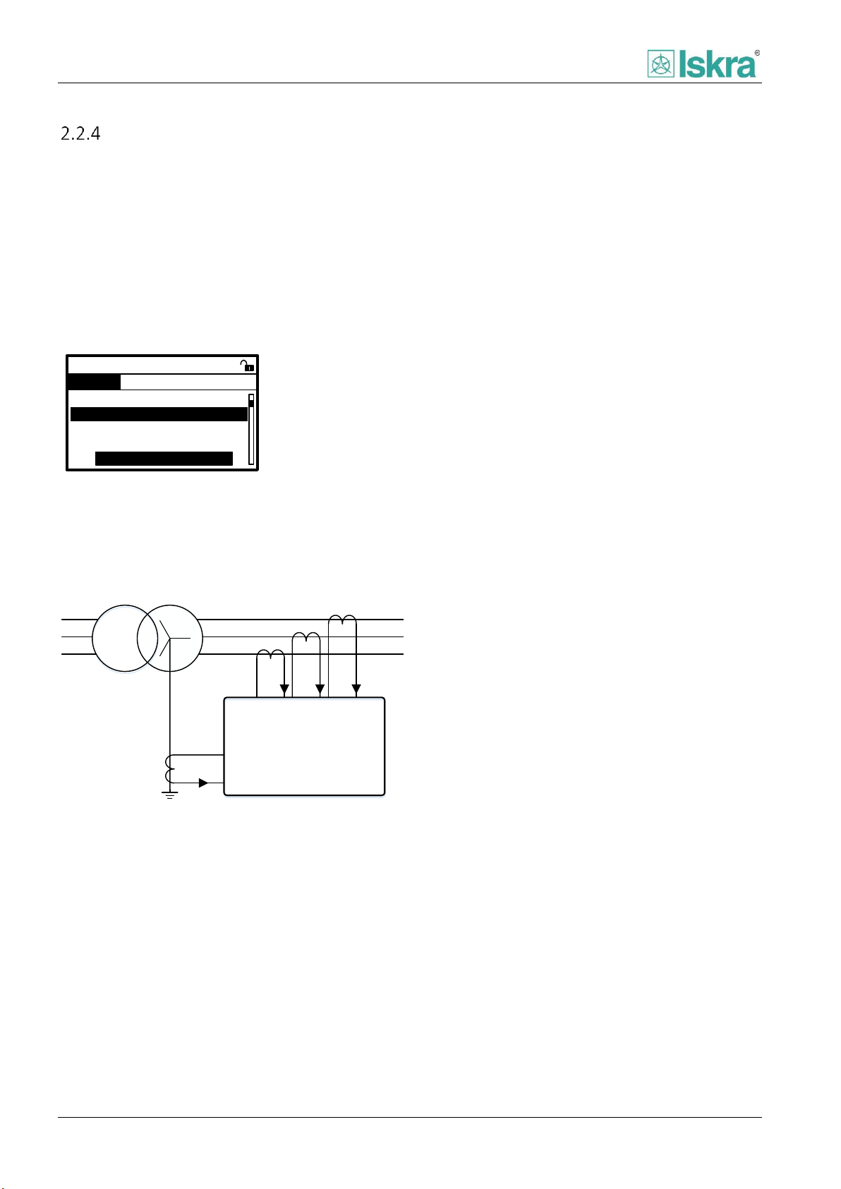
Restricted earth fault protection - ANSI code 64REF
Restricted Earth Fault function is one of advanced protection functions installed in FPC 200 protection relay. Protection
detects earth faults in power transformers, shunt reactors, neutral earthing transformers/reactors, or rotating machines.
Starpoint of protected element should be earthed. The starpoint CT and the phase CTs define the limits of absolutely
selective protection. Restricted earth fault protection is not applicable to busbar, type B of FPC 200 protection relay.
2.2.4.1 Functionality
Function compares calculated residual phase current
(3I0) with measured neutral point current Ie.
Figure 2.21 Example of parameter settings on HMI.
2.2.4.3 Connection scheme
Typical Connection scheme is shown on Figure 2.22.
2.2.4.2 Delays
Function includes following delays explained in Chapter
2.1:
Pickup delay
Trip delay
Drop-out delay
Figure 2.22: Connection scheme.
26 USER MANUAL FPC 200 - 3/2017

Functionality
Parameter
Range
Description
Enabled
No
Yes
Enabling protection function.
Operate mode
Off
Definitive time
Enabling protection function separately for each group level.
Pickup value
0,005 … 0,10 … 2,00 I
n_e
Limit of monitored current.
Trip delay
0,00 … 2,00 … 300,00 s
Delay of trip signal.
Pickup delay
0 … 5,00 … 1000 ms
Time stabilization of fault detection. As a filter of short disturbances on
measuring circuits. Time before protection starts.
Drop-out delay
0,00 … 0,20 … 60,00 s
Time stabilization of pickup signal. Time when the monitored value is
outside the operating range, but the protection does not stop yet.
Drop-out ratio
0,80 … 0,95 … 1,00 Ip
Drop-out value below which the protection drops.
Pickup block
None
Variable 1
Variable 2
Variable 3
Variable 4
Source of blocking signal.
Name
Description
Pickup
Total consecutive number of pickup signals.
Trip
Consecutive number of trip signals.
2.2.4.4 Setting parameters
Table 12: Restricted earth fault function parameters.
2.2.4.5 Counters
Table 13: Counters presented in restricted earth fault protection.
USER MANUAL FPC 200 - 3/2017 27

Functionality
37 Undercurrent
Enabled:
No
Pickup value: 0.7In
A
Trip delay: 0.4s
1A 1B
CONTROL SETTINGS
Pickup delay:
0.4s
A
Phase undercurrent protection - ANSI code 37
Phase to phase undercurrent is a function that protects the rotating machine or other elements of the power system from
low current.
2.2.5.1 Functionality
Undercurrent protection is used as time delayed
protection. It picks up when one of the phase currents
drops below the selected threshold. The function can be
enabled or disabled through corresponding menu.
The selection of pickup value, pickup delay as well as
drop-out ratio and drop-out delay helps the user to fine
tune the protection according to the project
specifications.
Figure 2.23: Phase undercurrent protection setting as seen on
HMI.
2.2.5.2 Delays
Function includes following delays explained in Chapter
2.1:
Pickup delay
Trip delay
Drop-out delay
2.2.5.3 Block settings
Pickup of any instance separately of protection can be
individually blocked by:
Any user defined signal [2.6.5].
Defined zero current level.
In addition the individual protection trip exhibits pulse
type if connected to trip relay [4.2.4.5.7, relay mapping
section], to ensure correct CBFP [2.6.1.10] functionality.
28 USER MANUAL FPC 200 - 3/2017

Functionality
Parameter
Range
Description
Enabled
No
Yes
Enabling protection function.
Operate mode
Off
On
Enabling protection function separately for each group level.
Pickup value
0,1 … 0,75 … 2,00 I
n_obj
Value at which fault conditions are considered.
Trip delay
0,00 … 1,50 … 300,00 s
Delay of trip signal
Pickup delay
10 … 20 … 1000 ms
Time stabilization of fault detection. As a filter of short
disturbances on measuring circuits. Time before protection starts.
Drop-out delay
0,00 … 0,20 … 60,00 s
Time stabilization of pickup signal. Time when the monitored value
is outside the operating range, but the protection does not stop
yet.
Drop-out ratio
1,01 … 1,20 … 3,00 Ip
Drop-out value below which the protection drops.
Current Supervision
Enabled
No
Yes
Enabling Current Supervision.
Zero I level
0,04 … 0,10 … 1
Level of current below which operation of protection is blocked.
Operation is blocked only in case of all three current amplitude Lx
are below Zero I level.
Recovery time
0,00 … 60 … 100 ms
Time of blocked protection after reaching Zero I level for Recovery
time.
Pickup block
None
Variable 1
Variable 2
Variable 3
Variable 4
Source of blocking signal.
Name
Description
Pickup
Total consecutive number of pickup signals.
Trip
Consecutive number of trip signals.
Pickup L1
Consecutive number of pickup signals detected in phase L1
Pickup L2
Consecutive number of pickup signals detected in phase L2
Pickup L3
Consecutive number of pickup signals detected in phase L3
2.2.5.4 Setting parameters
Table 14: Phase undercurrent protection function parameters.
2.2.5.5 Counters
Table 15: Counters presented in phase undercurrent protection.
USER MANUAL FPC 200 - 3/2017 29

Functionality
Protection function
Monitored currents
Overcurrent protection
Phase currents
Inrush detection
Inrush pickup
Inrush block
Max. inrush time
t < 20 ms
Inrush restraint
Inrush restraint function is a blocking function. The function can block overcurrent or earth fault overcurrent protection
from operating for pre-defined period of time.
2.2.6.1 Functionality
Transformer inrush current includes high 2nd harmonic
component. The Inrush restraint function is based on
evaluation of 2nd harmonic component present in the
inrush current. Inrush current detection is set for each
monitored current separately as defined in Table 16.
When transformer is energized high amount of 2
nd
harmonic component is present. In order to prevent
unwanted tripping Inrush restraint function can be used.
Another example is in combination with 50N/51N
protection function. When large object (e.g.
Transformer) is energized large amount of transients are
present. Because of that a large zero sequence can be
calculated which can trigger unwanted tripping of
50N/51N protection function. To once again prevent
unwanted tripping Inrush restraint should be used.
In order for inrush restraint to inhibit desired protection
its output should be assigned in parameter Inrush
restraint source which is present in all types of
overcurrent protection [2.2.1, 2.2.2].
2.2.6.2 Monitoring
Monitored currents are different for each protection
function.
Table 16: Monitored currents.
Figure 2.24: Inrush Restrain characteristic.
30 USER MANUAL FPC 200 - 3/2017

Functionality
Parameter
Range
Description
Enabled
No
Yes
Enabling of function.
Inrush pickup
1 … 15 … 70 %
Higher 2nd harmonic current limit in comparison to fundamental current, above
which the detection of inrush current is enabled.
Dropout delay
0 … 0,20 … 10 s
Max time
0 … 5,00 … 60 s
Max current
0,30 … 7,50 … 30,00 I
n_obj
Maximum value of fundamental current above which the protection is disabled.
Constant
Value
Description
Inrush drop-out delay
0,20 s
Time stabilization of pickup signal. Predefined time when the monitored
harmonic component value is outside the operating range, but the protection
does not stop yet.
Max inrush time
5,00 s
Predefined time when inrush restraint function is disabled.
Name
Description
Inrush counter
Total consecutive number of detected inrush signals.
2.2.6.3 Setting parameters
Table 17: Inrush restraint function parameters.
2.2.6.4 Predefined values
Table 18: Inrush restraint predefined values.
2.2.6.5 Counters
Table 19: counter presented in inrush restraint function.
USER MANUAL FPC 200 - 3/2017 31

Functionality
59 Overvoltage
Enabled:
Yes
Pickup value: 1.2Un
A
Trip delay: 0.4s
1A 1B 2A 2B 3A 3B
A
CONTROL SETTINGS
Pickup delay:
0.4s
2.3 Voltage based protections
Phase to phase overvoltage protection - ANSI code 59
Phase to phase overvoltage protection is one of the basic functions of FPC 200 numerical relays. It protects the feeder or
other elements of the power system from overvoltage. It comprises of time-delayed characteristics.
2.3.1.1 Functionality
Overvoltage protection is used as time delayed
protection. It picks up when voltage in one, two or three
phases exceeds the set threshold. The function can be
enabled or disabled through corresponding menu. The
settings of this function are applied to each of the three
phases to produce pickup and per each phase and
common trip signal.
Several overvoltage protection instances with different
settings can run independently at the same time.
The selection of pickup value, pickup delay as well as
drop-out ratio and drop-out delay helps the user to fine
tune the protection according to the project
specifications.
2.3.1.2 Measurements
The value of each phase to phase voltages is calculated
through measured phase voltages of measurement
voltage transformers. The input voltage is compared to
rated pickup voltage.
2.3.1.3 Delays
Function includes following delays explained in Chapter
2.1:
Pickup delay
Trip delay
Drop-out delay
2.3.1.4 Block settings
Pickup of any instance separately of protection can be
individually blocked by any user defined signal [2.6.5.].
Figure 2.25: Overvoltage protection setting as seen on HMI.
32 USER MANUAL FPC 200 - 3/2017

Functionality
Parameter
Range
Description
Enabled
No
Yes
Enabling protection function.
Operate mode
Off
On
Enabling protection function separately for each group level.
Pickup value
0,05 … 1,10 … 2,00 Un
Value at which fault conditions are considered.
Trip delay
0,00 … 2,00 … 300,00 s
Delay of trip signal
Pickup delay
0 … 5 … 1000 ms
Time stabilization of fault detection. As a filter of short
disturbances on measuring circuits. Time before protection starts.
Drop-out delay
0,00 … 0,20 … 60,00 s
Time stabilization of pickup signal. Time when the monitored value
is outside the operating range, but the protection does not stop
yet.
Drop-out ratio
0,80 … 0,95 … 0,99 Up
Drop-out value below which the protection drops.
Pickup block
None
Variable 1
Variable 2
Variable 3
Variable 4
Source of blocking signal.
Name
Description
Pickup
Total consecutive number of pickup signals.
Trip
Consecutive number of trip signals.
Pickup L12
Consecutive number of pickup signals detected in phase L12.
Pickup L23
Consecutive number of pickup signals detected in phase L23.
Pickup L31
Consecutive number of pickup signals detected in phase L31.
2.3.1.5 Setting parameters
Table 20: Overvoltage protection function parameters.
2.3.1.6 Counters
Table 21: Counters presented in overvoltage protection.
USER MANUAL FPC 200 - 3/2017 33

Functionality
Neut. voltage displ.
COUNTERS
0
Enabled:
1A 1B 2A 2B
No
Pickup:
Pickup value: 0,75
Trip delay:
1,5s
0
Trip:
CONTROL SETTINGS
Pickup delay:
5ms
Drop-out delay:
0,2s
0,95 Drop-out ratio:
BLOCK SETTINGS
Input: none
Input voltage:
Sum3U
Neutral voltage displacement - ANSI code 59N
Neutral voltage displacement protection is a function that detects residual overvoltage. It comprises of time-delayed
characteristics.
2.3.2.1 Functionality
Neutral voltage displacement protection is used as time
delayed protection. As voltage input this function can
use measured Ue or calculated 3U0 source. It picks up
when voltage from selected source exceed the selected
threshold. The function can be enabled or disabled
through corresponding menu.
Several voltage displacement protection instances with
different settings can run independently at the same
time.
The selection of pickup value, pickup delay as well as
drop-out ratio and drop-out delay helps the user to fine
tune the protection according to the project
specifications.
2.3.2.2 Measurements
The value of earth voltage can be chosen between direct
measurements Ue or calculated measurement using
symmetrical components 3U0. Input value can be set in
parameters settings for each instance of protection
separately.
2.3.2.3 Delays
Function includes following delays explained in Chapter
2.1:
Pickup delay
Trip delay
Drop-out delay
2.3.2.4 Block settings
Pickup of any instance separately of protection can be
individually blocked by any user defined signal [2.6.5.].
Figure 2.26: Neutral voltage displacement protection setting as
seen on HMI.
34 USER MANUAL FPC 200 - 3/2017

Functionality
Parameter
Range
Description
Enabled
No
Yes
Enabling protection function.
Operate mode
Off
On
Enabling protection function separately for each group level.
Pickup value
0,01 … 0,95 … 2,00 U
e_n
Value at which fault conditions are considered.
Trip delay
0,00 … 2,00 … 300,00 s
Delay of trip signal
Pickup delay
0 … 5 … 1000 ms
Time stabilization of fault detection. As a filter of short
disturbances on measuring circuits. Time before protection starts.
Drop-out delay
0,00 … 0,20 … 60,00 s
Time stabilization of pickup signal. Time when the monitored value
is outside the operating range, but the protection does not stop
yet.
Drop-out ratio
0,80 … 0,95 … 1,00 Up
Drop-out value below which the protection drops.
Input Voltage
Ue
3U0
Selector for input voltage to be used in protection.
Pickup block
None
Variable 1
Variable 2
Variable 3
Variable 4
Source of blocking signal.
Name
Description
Pickup
Total consecutive number of pickup signals.
Trip
Consecutive number of trip signals.
2.3.2.5 Setting parameters
Table 22: Neutral voltage displacement protection function parameters.
2.3.2.6 Counters
Table 23: Counters presented in neutral voltage displacement protection.
USER MANUAL FPC 200 - 3/2017 35

Functionality
27 Undervoltage
COUNTERS
0
Enabled:
1A 1B 2A 2B 3A 3B
No
Pickup:
Pickup value: 0,75
Trip delay:
1,5s
0
Trip:
CONTROL SETTINGS
Pickup delay:
5ms
Drop-out delay:
0,2s
0,95 Drop-out ratio:
BLOCK SETTINGS
Input: none
Fuse failure: Yes
A
Phase to phase undervoltage protection - ANSI code 27
Phase to phase undervoltage is a function that protects the feeder or other elements of the power system from low
voltage.
2.3.3.1 Functionality
Undervoltage protection is used as time delayed
protection. It picks up when ph-ph voltage drops below
the selected threshold. The function can be enabled or
disabled through corresponding menu.
Several ph-ph undervoltage protection instances with
different settings can run independently at the same
time.
The selection of pickup value, pickup delay as well as
drop-out ratio and drop-out delay helps the user to fine
tune the protection according to the project
specifications.
2.3.3.2 Delays
Function includes following delays explained in Chapter
2.1:
Pickup delay
Trip delay
Drop-out delay
2.3.3.3 Block settings
Pickup of any instance separately of protection can be
individually blocked by:
Any user defined signal [2.6.5].
Enabling Fuse failure protection [2.6.4].
In addition the protection is blocked when voltage drops
below 40 % of Un. To ensure the correct function of the
protection, the protection block is time delayed for a
brief moment after any condition for blocking has
expired. The individual protection trip exhibits pulse
type if connected to trip relay [4.2.4.5.7, relay mapping
section], to ensure correct CBFP [2.6.1.10] functionality.
Figure 2.27: Ph-Ph undervoltage protection setting as seen on
HMI.
36 USER MANUAL FPC 200 - 3/2017

Functionality
Parameter
Range
Description
Enabled
No
Yes
Enabling protection function.
Operate mode
Off
On
Enabling protection function separately for each group level.
Pickup value
0,1 … 0,95 … 2,00 Un
Value at which fault conditions are considered.
Trip delay
0,00 … 2,00 … 300,00 s
Delay of trip signal
Pickup delay
0,00 … 5,00 … 1000 ms
Time stabilization of fault detection. As a filter of short
disturbances on measuring circuits. Time before protection starts.
Drop-out delay
0,00 … 0,20 … 60,00 s
Time stabilization of pickup signal. Time when the monitored value
is outside the operating range, but the protection does not stop
yet.
Drop-out ratio
1,01 … 1,05 … 3,00 Up
Drop-out value below which the protection drops.
Pickup block
None
Variable 1
Variable 2
Variable 3
Variable 4
Source of blocking signal.
Name
Description
Pickup
Total consecutive number of pickup signals.
Trip
Consecutive number of trip signals.
Pickup L12
Consecutive number of pickup signals detected in phase L12.
Pickup L23
Consecutive number of pickup signals detected in phase L23.
Pickup L31
Consecutive number of pickup signals detected in phase L31.
2.3.3.4 Setting parameters
Table 24: Undervoltage protection function parameters.
2.3.3.5 Counters
Table 25: Counters presented in phase to phase undervoltage protection.
USER MANUAL FPC 200 - 3/2017 37

Functionality
27D U1 Undervoltage
COUNTERS
0
Enabled:
1A 1B 2A 2B
No
Pickup:
Pickup value: 0,75xUn
Trip delay:
1,5s
0
Trip:
CONTROL SETTINGS
Pickup delay:
5ms
Drop-out delay:
0,2s
0,95 Drop-out ratio:
BLOCK SETTINGS
Input: none
Fuse failure: Yes
Positive sequence undervoltage protection - ANSI code 27D
Positive sequence undervoltage protection is a function that protects the feeder or other elements of the power system
from wrong phase direction and low positive sequence of three phase system.
2.3.4.1 Functionality
Undervoltage protection is single analog input function,
used as time delayed protection. It picks up when
positive sequence voltage U1 drops below the selected
threshold. The function can be enabled or disabled
through corresponding menu.
Several protection instances with different settings can
run independently at the same time.
The selection of pickup value, pickup delay as well as
drop-out ratio and drop-out delay helps the user to fine
tune the protection according to the project
specifications.
2.3.4.2 Delays
Function includes following delays explained in Chapter
2.1:
Pickup delay
Trip delay
Drop-out delay
2.3.4.3 Block settings
Pickup of any instance separately of protection can be
individually blocked by:
Any user defined signal [2.6.5].
Enabling Fuse failure protection [2.6.4].
In addition the protection is blocked when voltage drops
below 40 % of Un. To ensure the correct function of the
protection, the protection block is time delayed for a
brief moment after any condition for blocking has
expired. The individual protection trip exhibits pulse
type if connected to trip relay [4.2.4.5.7, relay mapping
section], to ensure correct CBFP [2.6.1.10] functionality.
Figure 2.28: Positive sequence undervoltage protection setting
as seen on HMI.
38 USER MANUAL FPC 200 - 3/2017

Functionality
Parameter
Range
Description
Enabled
No
Yes
Enabling protection function.
Operate mode
Off
On
Enabling protection function separately for each group level.
Pickup value
0,1 … 0,95 … 2,00 Un
Value at which fault conditions are considered.
Trip delay
0,00 … 2,00 … 300,00 s
Delay of trip signal
Pickup delay
0,00 … 5,00 … 1000 ms
Time stabilization of fault detection. As a filter of short
disturbances on measuring circuits. Time before protection starts.
Drop-out delay
0,00 … 0,20 … 60,00 s
Time stabilization of pickup signal. Time when the monitored value
is outside the operating range, but the protection does not stop
yet.
Drop-out ratio
1,01 … 1,05 … 3,00 Up
Drop-out value below which the protection drops.
Pickup block
None
Variable 1
Variable 2
Variable 3
Variable 4
Source of blocking signal.
Name
Description
Pickup
Total consecutive number of pickup signals.
Trip
Consecutive number of trip signals.
2.3.4.4 Setting parameters
Table 26: Positive sequence undervoltage protection function parameters.
2.3.4.5 Counters
Table 27: Counters presented in positive sequence under voltage protection.
USER MANUAL FPC 200 - 3/2017 39
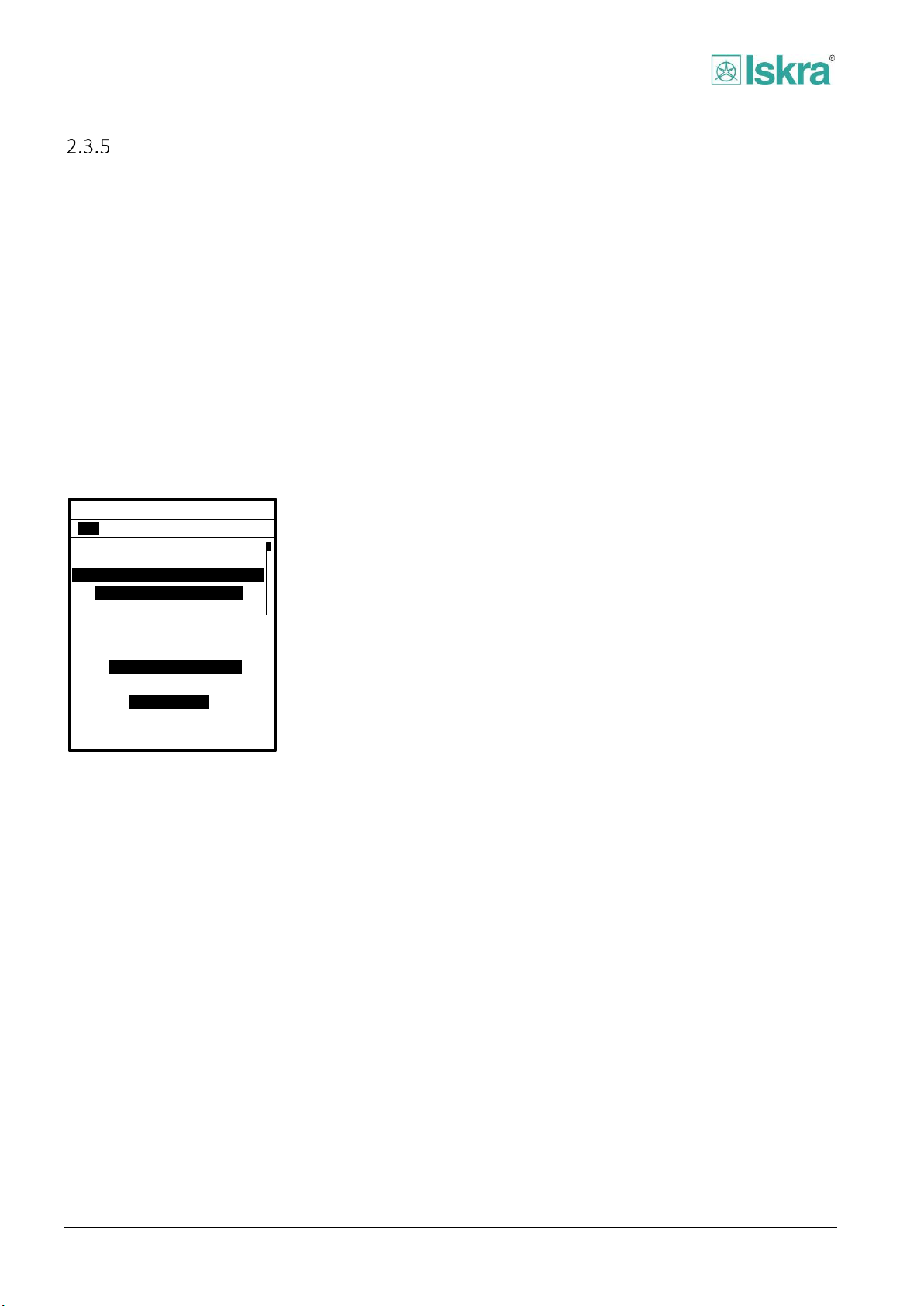
Functionality
27R Remanent UV
COUNTERS
0
Enabled:
1A 1B
No
Pickup:
Pickup value: 0,75xUn
Trip delay: 0,2s
0
Trip:
CONTROL SETTINGS
Pickup delay:
5ms
Drop-out delay:
0,2s
0,95 Drop-out ratio:
BLOCK SETTINGS
Input: none
Remanent undervoltage protection - ANSI code 27R
Remanent undervoltage protection is a function that prevents closing of the breaking element when voltage remaining by
rotating machines is still present on the load power line.
2.3.5.1 Functionality
Remanent undervoltage protection is a single phased
function, used as time delayed protection. It picks up
when ph-ph voltage U
threshold. The function can be enabled or disabled
through corresponding menu.
The selection of pickup value, pickup delay as well as
drop-out ratio and drop-out delay helps the user to fine
tune the protection according to the project
specifications.
drops below the selected
L12
2.3.5.2 Delays
Function includes following delays explained in Chapter
2.1:
Pickup delay
Trip delay
Drop-out delay
2.3.5.3 Block settings
Pickup of any instance separately of protection can be
individually blocked by:
Any user defined signal [2.6.5].
Enabling Fuse failure protection [2.6.4].
Protection is blocked when voltage drops below 5 % of
Un. To ensure the correct function of the protection, the
protection block is time delayed for a brief moment
after any condition for blocking has expired. The
individual protection trip exhibits pulse type if
connected to trip relay [4.2.4.5.7, relay mapping
section], to ensure correct CBFP [2.6.1.10] functionality.
Figure 2.29: Positive sequence undervoltage protection setting
as seen on HMI.
40 USER MANUAL FPC 200 - 3/2017

Functionality
Parameter
Range
Description
Enabled
No
Yes
Enabling protection function.
Operate mode
Off
On
Enabling protection function separately for each group level.
Pickup value
0,1 … 0,95 … 2,00 Un
Value at which fault conditions are considered.
Trip delay
0,00 … 2,00 … 300,00 s
Delay of trip signal
Pickup delay
0,00 … 5,00 … 1000 ms
Time stabilization of fault detection. As a filter of short
disturbances on measuring circuits. Time before protection starts.
Drop-out delay
0,00 … 0,20 … 60,00 s
Time stabilization of pickup signal. Time when the monitored value
is outside the operating range, but the protection does not stop
yet.
Drop-out ratio
1,01 … 1,05 … 3,00 Up
Drop-out value below which the protection drops.
Pickup block
None
Variable 1
Variable 2
Variable 3
Variable 4
Source of blocking signal.
Name
Description
Pickup
Total consecutive number of pickup signals.
Trip
Consecutive number of trip signals.
2.3.5.4 Setting parameters
Table 28: Remanent undervoltage protection function parameters.
2.3.5.5 Counters
Table 29: Counters presented in remanent undervoltage protection.
USER MANUAL FPC 200 - 3/2017 41

Functionality
81H Overfrequency
Enabled:
1A 1B 2A 2B
No
Pickup value:
0,50Hz
Trip delay:
1,5s
CONTROL SETTINGS
Pickup delay: 5ms
2.4 Frequency based protections
Overfrequency protection - ANSI code 81H
Overfrequency protection is a function that protects the feeder or other elements of the power system from undesirable
frequencies. It comprises of time-delayed characteristic and block on derivative of frequency with respect to time, which
can be used to prevent operation of breaking element in certain frequency transient conditions.
2.4.1.1 Functionality
Overfrequency protection is a function, used as time
delayed protection. It picks up when measured
frequency exceeds the selected threshold. The function
can be enabled or disabled through corresponding
menu.
Several protection instances with different settings can
run independently at the same time.
The selection of pickup value, pickup delay as well as
drop-out ratio and drop-out delay helps the user to fine
tune the protection according to the project
specifications.
Figure 2.30: Overfrequency protection setting as seen on HMI.
2.4.1.2 Measurement
Frequency is determined based on healthy analog
acquisition line measurement with priority of phase
voltage measurements first, than phase current
measurements. In addition the healthy line is
considered as a line which value is nearest to Un or In.
2.4.1.3 Delays
Function includes following delays explained in Chapter
2.1:
Pickup delay
Trip delay
Drop-out delay
2.4.1.4 Block settings
Pickup of any instance separately of protection can be
individually blocked by:
Any user defined signal [2.6.5].
derivative of frequency with respect to time
minimal voltage level
42 USER MANUAL FPC 200 - 3/2017

Functionality
Parameter
Range
Description
Enabled
No
Yes
Enabling protection function.
Operate mode
Off
On
Enabling protection function separately for each group level.
Pickup value
fn + 0,01 … 0,50 … 10,00 Hz
Value at which fault conditions are considered.
Trip delay
0,00 … 60,00 … 300,00 s
Delay of trip signal
Pickup delay
0,00 … 5,00 … 1000 ms
Time stabilization of fault detection. As a filter of short
disturbances on measuring circuits. Time before protection starts.
Drop-out delay
0,00 … 0,20 … 60,00 s
Time stabilization of pickup signal. Time when the monitored value
is outside the operating range, but the protection does not stop
yet.
Minimal voltage
0,00 … 0,65 … 1,00 Un
Any of phase to phase voltage amplitudes, below which the
protection block is considered.
Drop-out value
0,01 … 1,00 Hz
Drop-out value below which the protection drops.
Pickup block
None
Variable 1
Variable 2
Variable 3
Variable 4
Source of blocking signal.
Enable df/dt block
No
Yes
Enabling derivative of frequency with respect to time protection
block.
df/dt level
0,2 … 10,0 Hz/s
Value at which conditions for block are considered.
Block drop off delay
0 … 20 … 2000 ms
Time delay after block conditions have expired.
Name
Description
Pickup
Total consecutive number of pickup signals.
Trip
Consecutive number of trip signals.
2.4.1.5 Setting parameters
Table 30: Overfrequency protection function parameters.
2.4.1.6 Counters
Table 31: Counters presented in overfrequency protection.
USER MANUAL FPC 200 - 3/2017 43
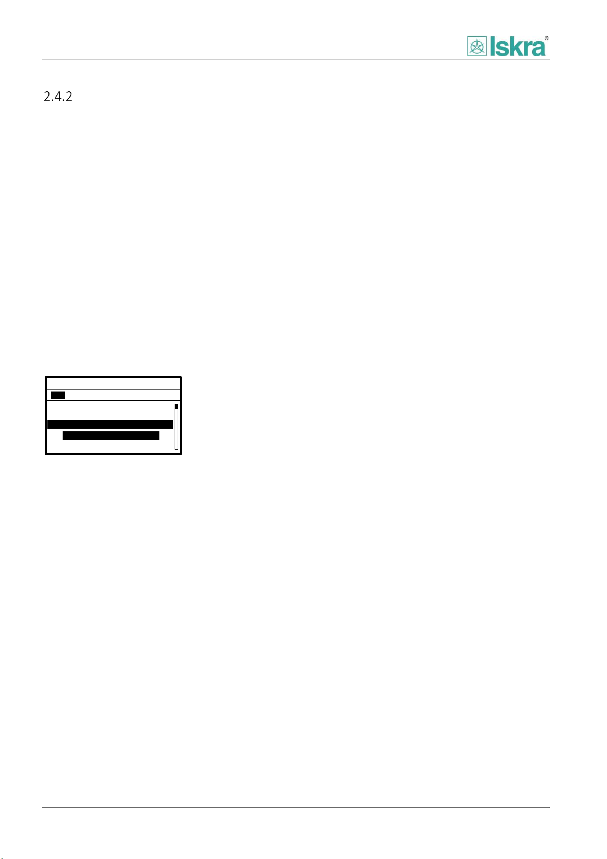
Functionality
81L Underfrequency
Enabled:
1A 1B 2A 2B
No
Pickup value:
-0,50Hz
Trip delay:
60,0s
CONTROL SETTINGS
Pickup delay: 5ms
Underfrequency protection - ANSI code 81L
Underfrequency protection is a function that protects the feeder or other elements of the power system from
undesirable frequencies. It comprises of time-delayed characteristic and block on derivative of frequency with respect to
time, which can be used to prevent operation of breaking element in certain frequency transient conditions .
2.4.2.1 Functionality
Underfrequency protection is a function, used as time
delayed protection. It picks up when measured
frequency is lower than the selected threshold. The
function can be enabled or disabled through
corresponding menu.
Several protection instances with different settings can
run independently at the same time.
The selection of pickup value, pickup delay as well as
drop-out ratio and drop-out delay helps the user to fine
tune the protection according to the project
specifications.
Figure 2.31: Underfrequency protection setting as seen on
HMI.
2.4.2.2 Measurement
voltage measurements first, than phase current
measurements. In addition the healthy line is
considered as a line which value is nearest to Un or In.
2.4.2.3 Delays
Function includes following delays explained in Chapter
2.1:
Pickup delay
Trip delay
Drop-out delay
2.4.2.4 Block settings
Pickup of any instance separately of protection can be
individually blocked by:
Any user defined signal [2.6.5].
derivative of frequency with respect to time
minimal voltage level
Frequency is determined based on healthy analog
acquisition line measurement with priority of phase
44 USER MANUAL FPC 200 - 3/2017

Functionality
Parameter
Range
Description
Enabled
No
Yes
Enabling protection function.
Operate mode
Off
On
Enabling protection function separately for each group level.
Pickup value
fn - 10,0 … -0,50 … - 0,01 Hz
Value at which fault conditions are considered.
Trip delay
0,00 … 60,00 … 300,00 s
Delay of trip signal
Pickup delay
0,00 … 5,00 … 1000 ms
Time stabilization of fault detection. As a filter of short
disturbances on measuring circuits. Time before protection starts.
Drop-out delay
0,00 … 0,20 … 60,00 s
Time stabilization of pickup signal. Time when the monitored value
is outside the operating range, but the protection does not stop
yet.
Minimal voltage
0,00 … 0,65 … 1,00 Un
Any of phase to phase voltage amplitudes, below which the
protection block is considered.
Drop-out value
0,01 … 1,00 Hz
Drop-out value below which the protection drops.
Pickup block
None
Variable 1
Variable 2
Variable 3
Variable 4
Source of blocking signal.
Enable df/dt block
No
Yes
Enabling derivative of frequency with respect to time protection
block.
df/dt level
0,2 … 10,0 Hz/s
Value at which conditions for block are considered.
Block drop off delay
0 … 20 … 2000 ms
Time delay after block conditions have expired.
Name
Description
Pickup
Total consecutive number of pickup signals.
Trip
Consecutive number of trip signals.
2.4.2.5 Setting parameters
Table 32: Underfrequency protection function parameters.
2.4.2.6 Counters
Table 33: Counters presented in underfrequency protection.
USER MANUAL FPC 200 - 3/2017 45

Functionality
81R ROCOF
Enabled:
1A 1B
No
Pickup val.:
0,20Hz/s
Trip delay:
0,02s
CONTROL SETTINGS
Pickup delay: 0ms
A
Rate of change of frequency protection - ANSI code 81R
Rate of change of frequency ROCOF protection is a function that indicated severity of the frequency transient. The result
can be used as preventive load shedding. It comprises of time-delayed characteristic.
2.4.3.1 Functionality
ROCOF protection is a function, used as time delayed
protection. It picks up when measured rate of change
frequency exceeds the selected threshold. The
frequency threshold can be set on negative, positive or
both rates of change. The function operation can be
enabled or disabled through corresponding menu.
The selection of pickup value, pickup delay as well as
drop-out ratio and drop-out delay helps the user to fine
tune the protection according to the project
specifications.
Figure 2.32: ROCOF protection setting as seen on HMI.
2.4.3.2 Measurement
Rate of change of frequency is determined based on
frequency change over specific amount of time. The
value is averaged to ensure proper function.
2.4.3.3 Delays
Function includes following delays explained in Chapter
2.1:
Pickup delay
Trip delay
Drop-out delay
2.4.3.4 Block settings
Pickup of any instance separately of protection can be
individually blocked by any user defined signal [2.6.5]. In
addition ROCOF function is blocked if all phase voltages
drops below 0,5 Un.
46 USER MANUAL FPC 200 - 3/2017

Functionality
Parameter
Range
Description
Enabled
No
Yes
Enabling protection function.
Mode
Off
Positive
Negative
Both
Selection of different types of protection operation modes.
Pickup value
0,2 … 0,50 … 10,00
Value at which fault conditions are considered. The value is
presented in absolute positive number.
Trip delay
0,10 … 0,20 … 300,00 s
Delay of trip signal
Pickup delay
0,00 … 1000 ms
Time stabilization of fault detection. As a filter of short
disturbances on measuring circuits. Time before protection starts.
Drop-out delay
0,00 … 0,20 … 60,00 s
Time stabilization of pickup signal. Time when the monitored value
is outside the operating range, but the protection does not stop
yet.
Drop-out ratio
0,80 … 0,95 … 1,00 Pickup
Drop-out ratio below which the protection drops.
Pickup block
None
Variable 1
Variable 2
Variable 3
Variable 4
Source of blocking signal.
Name
Description
Pickup
Total consecutive number of pickup signals.
Trip
Consecutive number of trip signals.
2.4.3.5 Setting parameters
Table 34: ROCOF protection function parameters.
2.4.3.6 Counters
Table 35: Counters presented in ROCOF protection.
USER MANUAL FPC 200 - 3/2017 47

Functionality
I
dt
d
1
Equation 4: Heating and cooling differential equation.
2
n
I
I
I
Equation 5: Temperature which would be reached at
specific current.
t
II
e )(
0
Equation 6: temperature which would be reached at
specific current I in specific time t, started from
0
temperature.
I – Present machine current.
ΘI – final temperature that would be reached in infinite
amount of time, maintaining constant current.
Θ0 – Initial temperature.
Θ – Current temperature.
τ – Heating and cooling time constant.
t – time
When the circuit breaker disconnects
the line because of thermal
protection, the trip signal resets,
otherwise the CBFP protection of the
circuit breaker Switch module would
operate.
The closing of circuit breaker is inhibited
until the temperature fall below the set
High temperature value.
2.5 Power and machine protections
Thermal overload protection – ANSI code 49T
This protection is designed to protect power lines, power cables and passive cooling transformers against thermal
overload. The function estimates temperature of the object according to measured phase currents.
2.5.1.1 Functionality
The algorithm calculates the relative temperature of
protected device based on current measurement. The
temperature is calculated for each phase separately and
only highest current is displayed. The monitored value
for protection is the highest calculated temperature.
When the alarm or trip temperature value is reached,
the appropriate alarm or trip temperature warning
signal is stated. The alarm and trip temperature value
parameter can be set in per cent of machine heating. In
order to make the calculation of time to trip possible,
the heating time constant must be set.
The k-factor of individual machine is similar to service
factor and is maximal allowed permanent current of the
object. K-factor is determined by materials used,
construction properties and it is defined according to
the environment where the protected device is used.
2.5.1.1.1 High temperature mode
Start on trip
High temperature signal starts with trip signal and ends
when temperature drops below high temperature value.
2.5.1.1.2 Heating and cooling equation
Start on high temperature
Signal high temperature starts as the high temperature
value is reached and ends when temperature drops
below high temperature value.
48 USER MANUAL FPC 200 - 3/2017

Functionality
Parameter
Range
Description
Enabled
No
Yes
Enabling protection function.
Operation Mode
Off
On
Enabling protection function separately for each group level.
k-factor
0,1 … 1,10 … 4,0 In
Maximal permanent thermal current allowed relative to the nominal
current.
Alarm temperature value
45,0 … 90,0 … 99,0 %
Alarm limit,
alm
High temperature value
45,0 … 95,0 … 99,0 %
Signal intendent to inhibit closing of breaking device.
Heating time constant
1,0 … 100,0 … 1000,0 min
Heating and cooling time constant, τ
High temperature mode
Start on trip
Start on high temperature
Pickup block
None
Variable 1
Variable 2
Variable 3
Variable 4
Source of blocking signal.
Name
Description
Temperature L1
Calculated machine temperature in phase L1, 100% = 1.000 pieces.
Temperature L2
Calculated machine temperature in phase L2, 100% = 1.000 pieces.
Temperature L3
Calculated machine temperature in phase L3, 100% = 1.000 pieces.
Pickup
Total consecutive number of pickup signals.
Trip
Consecutive number of trip signals.
Temperature
Calculated machine temperature , biggest phase, 100% = 1.000
pieces.
2.5.1.2 Setting parameters
Table 36: Thermal overload function parameters.
2.5.1.3 Counters
Table 37: Counters presented in thermal overload function.
USER MANUAL FPC 200 - 3/2017 49

Functionality
When the circuit breaker disconnects the
line because of thermal protection, the trip
signal resets, otherwise the CBFP
protection of the circuit breaker Switch
module would operate.
The closing of circuit breaker is inhibited
until the temperature fall below the set
High temperature value.
I
dt
d
1
Equation 7: Heating and cooling differential equation.
Machine Thermal Overload Protection - ANSI code 49M
Machine thermal overload protection (MTOP) is designed to protect machines with different heating and cooling constant
against thermal overload. The function estimates temperature of the object according to measured phase currents its
characteristics and ambient temperature.
2.5.2.1 Functionality
The algorithm calculates the relative temperature of
protected device based on current measurement. The
temperature is calculated for each phase separately and
only highest current is displayed. The monitored value
for protection is the highest calculated temperature.
When the alarm or trip temperature value is reached,
the appropriate alarm or trip temperature warning
signal is stated. The alarm and trip temperature value
parameter can be set in percentage of machine heating.
In order to make the calculation of time to trip possible,
the heating and cooling time constant parameters must
be set. Information about the heating constant for
particular machine can be found in device tables or
acquired from the manufacturer of the protected
equipment. For passive cooling machines, the cooling
constant is equal to the heating constant.
The protection detects the overload, when the maximal
allowed permanent thermal current I
the start of overheating of protected element, is
exceeded. The service factor has to be set. The constant
is defined as service factor = I
maximal thermal current and the I
current of the protected device.
max
/ I
max
n_obj
n_obj
is nominal
, which causes
, where the I
max
is
Current over temperature values are written to
Temperature Lx outputs separately for each phase. The
value is written as a relative value, where 100 %
represents that the maximal allowed over temperature
is reached. By resetting values on outputs, their start
values can be set by user interface. At the device startup, this outputs are reset to zero, which represents no
over temperature.
Equations below are used in protection algorithm.
2.5.2.1.1 Heating and cooling equation
The service factor is maximal allowed permanent
current of the machine. It is determined by materials
used, construction properties and it is defined according
to the environment where the protected device is used.
Usually it is available from property tables supplied by
the manufacturer.
Trip signal is stated when current in any phase exceeds
I
and temperature exceeds set trip temperature.
max
Hot state indicates the level above which it is
considered that machine is now at nominal operating
temperature if set correctly.
50 USER MANUAL FPC 200 - 3/2017

Functionality
2
n
I
I
I
Equation 8: Temperature which would be reached at
specific current.
t
II
e )(
0
Equation 9: temperature which would be reached at
specific current I in specific time t, started from
0
temperature.
I – Present machine current.
ΘI – final temperature that would be reached in infinite
amount of time, maintaining constant current.
Θ0 – Initial temperature.
Θ – Current temperature.
τ – Heating or cooling time constant.
t - time
HCRK
HH
1
run
start
t
starttripstarthigh
e
2
1
2
1
I
I
Kk
N
2
175
LRC
IK
2
230
LRC
IK
amb
amb
amb
k
max
max_max
calculated heat can be taken into account by using the
Current unbalance factor.
Equation 12 Current unbalance current influence.
kN – correction factor.
I1 – positive sequence current.
I2 – Negative sequence current.
K - Current unbalance factor.
Recommended parameter settings of Current
unbalance factor:
2.5.2.1.2 Hot state temperature detection of the
machine
It is considered that the machine is in hot state when
calculated temperature exceeds Hot state level.
Equation 10 Hot state level equation.
KH – Hot state level
ΘH – Temperature level above which is considered hot state of
the machine.
HCR – Hot to cold ratio
2.5.2.1.3 Start of overheated machine Inhibition
In certain cases when start of the machine would cause
the temperature to exceed insulation class of the
machine the high temperature signal is stated. The
estimation is based on equation:
Equation 11 High temperature equation.
t
– correction factor.
start
I
– positive sequence.
start
Θ
– Thermal class of machine.
start
Θ
– Thermal class of machine.
high
Θ
– Thermal class of machine.
trip
2.5.2.1.4 Negative sequence component Influence
Additional negative sequence current can occur in
rotating machines with coiled rotors. Difference in
USER MANUAL FPC 200 - 3/2017 51
Equation 13 Typical current unbalance factor.
Equation 14 Conservative current unbalance factor.
I
– Locked rotor current of rotating machine.
LRC
2.5.2.1.5 Accounting for ambient temperature
The function can take into account the ambient
temperature. Temperature can be obtained from
external sensor or most common maximum operating
temperature of machine 40 °C is used.
Equation 15 Calculation of ambient temperature influence.
Equation 16 Equivalent current calculation.
k
– Correction factor.
amb
Θ
– Thermal class of machine.
max
Θ
Θ
Ieq – Equivalent machine current.
– Maximum ambient themperature.
amb_max
– Current ambient themperature.
amb_max
2.5.2.1.6 Time to trip and time to drop out calculation
equation
Time to trip and time to drop out calculation equation
where there the longest time of separate phases is

Functionality
2
0
ln
I
I
t
Parameter
Range
Description
Enabled
No
Yes
Enabling protection function.
Operate mode
Off
On
Enabling protection function separately for each group level.
Alarm temperature value
10,0 … 80,0 … 200,0 %
Alarm limit,
alm
Trip temperature value
100,0 … 200,0 %
Critical temperature limit..
Running time constant
0,1 … 15,0 … 1000,0 min
Heating time constant τ.
Stopped time constant
0,1 … 30,0 … 1000,0 min
Cooling time constant τ.
Start-up time
0,1 … 10,0 … 1000,0 s
Full load start up time of the machine.
Start-up current
0,50 … 6,00 … 20,00 I
n_obj
Full load start up current of the machine.
Service factor
0,70 … 1,00 … 4,00 I
n_obj
Maximal permanent thermal current allowed relative to the nominal
current.
Hot to cold time ratio
0,00 … 0,80 … 1,00
Allowed ratio between hot and cold start-up time.
Hot state level
0,00 … 50 … 100 %
Temperature above which is considered that machine is in hot state.
Current unbalance factor
0,00 … 4,50 … 9,00
Influence of negative sequence component to heating of machine.
Insulation max
temperature
70 … 130 … 250 °C
Machine insulation class interpreted in maximal insulation temperature
Pickup block
None
Variable 1
Variable 2
Variable 3
Variable 4
Source of blocking signal.
Ambient source
None
Probe 8
Usage of external ambient source
Ambient constant
20 … 40 … 70
Constant of room temperature impact if Ambient source is set None
Maximal temperature
20 … 40 … 70
Maximal temperature for machine to work.
Name
Description
Temperature L1
Calculated machine temperature in phase L1, 100% = 1.000 pieces.
Temperature L2
Calculated machine temperature in phase L2, 100% = 1.000 pieces.
Temperature L3
Calculated machine temperature in phase L3, 100% = 1.000 pieces.
Temperature
Calculated machine temperature , biggest phase, 100% = 1.000
pieces.
Overload
Total consecutive number of Overload signals.
Pickup
Total consecutive number of pickup signals.
Trip
Consecutive number of trip signals.
presented in time to drop out and shortest time is
presented in time to trip.
Equation 17: Time to Trip.
2.5.2.2 Setting parameters
Θ2 – final temperature.
t – time in seconds.
Table 38: Thermal overload function parameters.
2.5.2.3 Counters
Table 39: Counters presented in thermal overload function.
52 USER MANUAL FPC 200 - 3/2017

Functionality
38/49T Temp. monitor
COUNTERS
Trip:
Alarm:
220°C
220°C
Alarm:
Trip:
0
0
Enabled: Yes
1 2 3 4 5 6 7 8
Temperature monitoring - ANSI code 38/49T
Temperature monitoring is associated with additional external module including up to 8 resistance temperature detectors
(RTDs). Correct external module connection is required for protection to perform as specified.
2.5.3.1 Functionality
Temperature monitoring is a function, used as
temperature dependent protection. Alarm signal is
stated when measured temperature exceeds the
selected alarm threshold. Trip signal of function is set
when measured temperature exceeds the selected trip
threshold. For each RTD there are separate function
settings.
The function operation can be enabled or disabled
individually for each RTD.
2.5.3.3 Delay
To ensure correct operation of function an individual
measurement needs to exceed desired threshold of
alarm or trip at least twice in a row.
2.5.3.4 Block of the protection
In addition the individual protection trip exhibits pulse
type if connected to trip relay [4.2.4.5.7, relay mapping
section], to ensure correct CBFP [2.6.1.10] functionality.
Figure 2.33: Temperature monitor setting as seen on HMI.
2.5.3.2 Measurement
Measurement is performed using specific algorithms to
interpret measurement of probes resistance. RTDs are
using 3-wire connection type to temperature sensors.
2.5.3.5 RTD fault
RTD fault signal is provided to ensure the correct
operation of external module as well as its sensors. If
the connection to one of the sensors is terminated or
short-circuited, the RTD fault signal is activated. The
signal remains active as long as the fault persists. The
fault can only occur if a protection of a malfunction
sensor is active.
USER MANUAL FPC 200 - 3/2017 53

Functionality
Parameter
Range
Description
Enabled
No
Yes
Enabling protection function.
Alarm temperature
-35 … 220 °C
Temperature limit that triggers alarm signal
Trip temperature
-35 … 220 °C
Temperature limit that triggers trip signal
Pickup block
None
Variable 1
Variable 2
Variable 3
Variable 4
Source of blocking signal.
Name
Description
Alarm
Total consecutive number of alarm signals presented for each
sensor separately.
Trip
Consecutive number of trip signals presented for each sensor
separately.
RTD fault
Fault counter of any active probe.
2.5.3.6 Setting parameters
Table 40 Temperature monitoring parameters selection.
2.5.3.7 Counters
Table 41: Counters presented in temperature monitoring function.
54 USER MANUAL FPC 200 - 3/2017

Functionality
48/51LR/14
Enabled:
:
No
CONTROL SETTINGS
Start-up time:
300,0s
300,0s
Locked start t:
300,8s
Stall time:
COUNTERS
Trip counter:
Excesive start:
Locked start:
0
0
0
Stall:
0
Rotation signal is usually connected to an
external digital input, which is connected
to a rotating machine rotation detector.
Locked rotor protection, excessive starting time - ANSI code 48/51LR/14
Failure of a rotating machine to accelerate when its stator is energized can be caused by several types of abnormal
conditions, including mechanical failure of the machine or load bearings, low supply voltage, or an open circuit in one
phase of a three-phase voltage supply. When a rotating machine stator winding is energized with the rotor stationary, the
machine performs like a transformer with resistance-loaded secondary winding. Stator winding currents may typically
range from three to seven or more times the rated full-load value, depending on the machine design and supply system
impedance.
Although the rotating machine starting current does drop off near full speed, this effect is normally neglected, providing
some safety margin from relay operation during rotor acceleration.
2.5.4.1 Functionality
Considering the current amplitude on start-up is at
maximum most of the time, the algorithm takes into
account that the start-up current is constant and is
equal to maximum start-up current. Therefore the
allowed start-up time is constant. This function
distinguishes between different rotating machine
conditions, regarding current and digital input states.
Trip of the function is considered as soon as any stated
condition is detected. When rotating machine reaches
stopped state, all signals are set to zero and all timers
are reset.
Figure 2.34 Locked rotor function parameters as seen on HMI.
Table 42 Locked rotor, excessive start time on HMI.
2.5.4.1.1 Excessive start – ANSI 48
Condition is considered if starting [2.6.4.3.2] signal is set
for longer period than Start-up time of the machine,
while rotation [2.5.4.3] signal is present.
2.5.4.1.2 Locked start – ANSI 51LR
Condition is considered if starting signal is set for longer
period than Locked start time of the machine, while
there is no rotation signal present.
2.5.4.1.3 Stall – ANSI 14
Condition is considered if stalling [2.6.4.3.6] signal is set
for longer period than Stall time of the machine.
USER MANUAL FPC 200 - 3/2017 55

Functionality
Parameter
Range
Description
Enabled
No
Yes
Enabling protection function.
Start-up time
0,5 … 5,0 … 300,0 s
Maximum machine start time with rotor rotation detection.
Locked start time
0,1 … 3,0 … 300,0 s
Maximum machine start time with blocked rotor detection.
Stall time
0,1 … 1,0 … 300,0 s
Maximum machine stall time during normal operation.
Digital input
Description
Rotation
External indication about machine rotation.
Name
Description
Trip
Consecutive number of trip signals.
Excessive start
Consecutive number of excessive start signals.
Locked start
Consecutive number of locked start signals.
Stall
Consecutive number of stall signals.
2.5.4.2 Setting parameters
Table 43: Locked rotor function parameters.
2.5.4.3 Associated digital inputs
Table 44 Digital inputs associated with the function.
2.5.4.4 Counters
Table 45: Counters presented in locked rotor protection.
56 USER MANUAL FPC 200 - 3/2017

Functionality
Parameter
Range
Description
Enabled
No
Yes
Enabling protection function.
Delay between starts
0 … 5 … 5400 s
Minimum required time between two machine starts.
Enable allowed starts
No
Yes
Yes – Activated allowed starts functionality.
No – Deactivated allowed starts functionality.
Allowed starts
1 … 10 … 60
Number of allowed machine starts inside Starts period.
Starts period
1 … 60 … 360 min
Machine starts period.
Enable consecutive starts
No
Yes
Yes – Activated consecutive starts functionality.
No – Deactivated Consecutive starts functionality.
Consecutive starts period
1 … 10 … 90 min
Consecutive starts period.
Allowed cold starts
1 … 2 … 5
Number of allowed consecutive cold starts.
Allowed hot starts
1 … 5
Number of allowed consecutive hot starts.
Block settings 1
None
Variable 1
Variable 2
Variable 3
Variable 4
Input of blocking Inhibit signal of engine start.
Name
Description
Lockout time
Time of Inhibit signal dropout in real time, in seconds.
Current starts
Current number of starts remaining, cold starts if the cold state is
active and hot starts if hot state is currently present.
Consecutive cold starts
Current number of lapsed cold starts in certain short period of
time.
Consecutive hot starts
Current number of lapsed hot starts in certain short period of time.
Inhibit counter
Consecutive number of inhibit signals.
Starts counter
Consecutive number of start signals.
Starts per hour - ANSI code 66
Protection Starts per hour is meant to prevent too frequent starts of the rotating machine in a given time window.
2.5.5.1 Functionality
Rotating machine manufacturers usually define allowed number of starts within given time period by one of two criteria:
How many starts are allowed within one hour
How many consecutive starts are allowed according to current thermal state of the machine
This protection can be set up by either of those criteria, or even both of them. User can also define minimum delay
between starts. When any of given criteria is reached the protection inhibits starting of the machine by blocking the
circuit breaker closing command. Thermal state of the machine is determined by Thermal overload protection [2.5.1],
which needs to be enabled for proper thermal detection of the machine.
Table 46 Starts per hour function parameters.
2.5.5.2 Counters
Table 47: Counters presented in starts per hour function.
USER MANUAL FPC 200 - 3/2017 57

Functionality
Float switch
Leak and
preassure switch
It is recommended that pressure switch
immediately trips CB while float switch
indicates fault that needs to be treated as
soon as possible to prevent further damage
to transformer.
Parameter
Range
Description
Enabled
No
Yes
Enabling protection function.
Operate mode
Off
On
Enabling protection function separately for each group level.
Trip delay
0,00 … 1,00 … 300,00 s
Delay of trip signal.
Pickup delay
0 … 5 … 1000 ms
Time stabilization of fault detection. As a filter of short disturbances on
measuring circuits. Time before protection starts.
Drop-out delay
0,00 … 0,20 … 60,00 s
Time stabilization of pickup signal. Time when the monitored value is
outside the operating range, but the protection does not stop yet.
Pickup block
None
Variable 1
Variable 2
Variable 3
Variable 4
Source of blocking signal.
Digital input
Description
Buchholz 1
External trigger of Buchholz relay 1 protection.
Buchholz 2
External trigger of Buchholz relay 2 protection.
Name
Description
Pickup
Total consecutive number of pickup signals.
Trip
Consecutive number of trip signals.
Buchholz relay protection – ANSI code 63
2.5.6.1 Description
Buchholz relay protection is external protection that
mechanically controls oil level and oil flow in certain
power transformers. Protection consists of two
instances one dedicated to Leak and pressure switch
and second to Float switch. Float switch indicates slow
air build up in Buchholz cylinder, usually indicating
minor discharge fault in transformer. While Leak and
pressure switch detects forceful oil flow usually
indicating major short-circuit related fault in
transformer.
Figure 2.35 Schematic of Buchholz relay operation.
2.5.6.1.1 Setting parameters
Table 48 Buchholz function parameters.
2.5.6.1.2 Associated digital inputs
Table 49 Digital inputs associated with the protection.
2.5.6.1.3 Counters
Table 50: Counters presented in buchholz protection.
58 USER MANUAL FPC 200 - 3/2017

Functionality
It is recommended that external trip
temperature signal immediately trips CB
while external alarm temperature signal
acts as a warning that indicates overheating
of the machine.
Parameter
Range
Description
Enabled
No
Yes
Enabling protection function.
Operate mode
Off
On
Enabling protection function separately for each group level.
Trip delay
0,00 … 1,00 … 300,00 s
Delay of trip signal.
Pickup delay
0 … 5 … 1000 ms
Time stabilization of fault detection. As a filter of short disturbances on
measuring circuits. Time before protection starts.
Drop-out delay
0,00 … 0,20 … 60,00 s
Time stabilization of pickup signal. Time when the monitored value is
outside the operating range, but the protection does not stop yet.
Pickup block
None
Variable 1
Variable 2
Variable 3
Variable 4
Source of blocking signal.
Digital input
Description
Thermal switch 1
External trigger of Thermal switch 1 protection.
Thermal switch 2
External trigger of Thermal switch 2 protection.
Name
Description
Pickup
Total consecutive number of pickup signals.
Trip
Consecutive number of trip signals.
Thermal switch protection – ANSI code 26
2.5.7.1 Description
Thermal switch protection is an external protection
device, mounted on the machine. Thermal switch
usually consists of two binary signals, by which one is
alarm temperature signal and another is trip
temperature signal. Protection consists of two instances
first dedicated to external trip signal and second to
external alarm signal.
2.5.7.2 Setting parameters
Table 51 Thermal switch function parameters.
2.5.7.3 Associated digital inputs
Table 52 Digital inputs associated with the function.
2.5.7.4 Counters
Table 53: Counters presented in thermal switch protection.
USER MANUAL FPC 200 - 3/2017 59

Functionality
Interlock
Cause of blocking
Command already in execution
Command already in progress
Trip present
Trip still present
System
Incorrect mode (Local/Remote)
Bay
Open or Close blocked or allowed by external input
Status
Circuit breaker in fault or unknown position
Maximal number of operations
Maximal number of mechanical operations of switchgear element exceeded
I2t
Contact worn out
2.6 Automation and diagnostic
FPC 200 can be used to control and monitor breaking devices.
Circuit breaker control and monitoring - ANSI 94/69 with integrated circuit breaker
failure - ANSI 50BF/62BF function.
2.6.1.1 Description
FPC 200 is used to control breaking devices equipped
with different types of closing and tripping contacts.
Therefore its output relays can be configured for nonlatched, latched or pulse operation to match any type of
breaking device.
2.6.1.2 Integrated circuit breaker
This function controls the breaking device. It works in
conjunction with automatic re-closer and hierarchical
interlocking with bypass ability. Detection of breaker
failure when trip command is sent is included.
It performs the following functions:
Trip by
protection configured to trip the circuit breaker
remote control by communication (blocked if
remote mode is off)
external protection
open command by HMI
Close by
automatic re-closer
remote control by communication (blocked if
remote mode is off)
closing command by HMI
Block by
trip circuit supervision (TCS)
SF6 fault
interlocking
Different internal logic functions are used to prevent
sending of open or close commands to circuit breaker.
They are called interlocking. FPC 200 can check
following interlocking (Table 54) prior to command
execution. Block diagram is presented on Figure 2.36
Table 54: Interlocking description.
60 USER MANUAL FPC 200 - 3/2017

Functionality
Interlocking
Trip circuit supervision (74TCS)
SF6
Overcurrent (50/51)
Earth fault overcurrent (50/51|N/G)
External protection
Auto-reclosure (79) Open command
Open command
by local display
Remote open command
Remote close command
Block remote control
Breaker closed
Auto-reclosure (79) Close command
Close command by local display
Block
Open
Close
≤1
≤1
&
≤1
&
≤1
&
≤1
Figure 2.36: Blocking diagram.
2.6.1.3 Control settings
2.6.1.3.1 Command timeout
Time used for a device to wait for switchgear element to
change state. If this time is exceeded and no return
information was given, an error Command failed popup
window will be displayed on HMI in addition an
information can be accessed using the available
communication protocol.
2.6.1.3.2 Operation time
Time measured from moment when device relay
contacts initiate switchgear open command till moment
when switchgear element primary contacts open. This
information is vital calculation of cumulative breaking
current of primary contacts [2.6.1.7]. The information is
usually available in circuit breaker technical data.
2.6.1.4 Command objects
Command objects defines the source of which the
switchgear element commands are executed.
Commands via HMI and DI are always allowed and
commands via communication can be allowed in
addition. In case that Remote enabled signal is assigned
to DI, this setting is not displayed on HMI.
2.6.1.5 Interlocking system
Interlocking system serves as a switch allowing remote
or local commands to be issued. Local commands are
always allowed while remote command can be allowed
by using parameter via HMI, MiQen software, Modbus
table and DI.
2.6.1.6 Max trip open (MTO)
Max trip open is a cumulative counter of CB trips. Alarm
and Block signal can be set after a certain number of trip
signals dedicated to open CB has passed. If number
present exceeds a Block set limit a circuit breaker MTO
interlock will engage.
2.6.1.7 Cumulative breaking current I
Function indicates the cumulative breaking current in
square kilo amperes. Total sum number information of
each phase is provided in appropriate diagnostic section
[4.2.4.1.3]. Alarm and block signal can be set for certain
amount of cumulative breaking current. If number
present exceeds a Block set limit a circuit breaker I2t
interlock will engage.
Current calculation is performed every time a command
open is executed or trip signal dedicated to open a CB is
2
t
USER MANUAL FPC 200 - 3/2017 61

Functionality
Digital input
Description
Open allow
Allowing executing of CB open command.
Open block
Inhibition of CB open command.
Close allow
Allowing executing of CB close command.
Close block
Inhibition of CB close command.
To use this function properly, it is necessary
that CB position is known to the device.
Fault
Fault end
CBFP open command
Trip open command
Fault start
Fault start
CBFP delay
Minimal pulse Minimal pulse
initiated. The current readout is performed at exact
time of CB contact separation by taking into account a
user definable parameter CB operation time.
2.6.1.7.1 Readout
Measurements are accessed via:
HMI diagnostic [4.2.4.1.3],
MiQen software,
Communication link.
The value can be reset in counters section of CB.
2.6.1.8 Bay
Interlocking bay is intended to allow or block operation
of CB by using DI signals. Bay restrictions influence
manual and remote commands excluding trip signals
registered for tripping CB.
2.6.1.8.1 Associated digital inputs
2.6.1.10 Circuit breaker failure (CBFP)
This function is designed to detect when a breaker does
not open when a trip is sent. User defined delay timer is
started every time trip command is sent to trip relay
[4.2.4.5.7, relay mapping section]. In case a fault
condition is not cleared in that time, the CBFP open
command is initiated.
Figure 2.37 Example of CBFP operation.
2.6.1.11 CB Ready
CB ready is intended to indicate the ready status of
circuit breaker. Multiple DI signals can be assigned to
indicate ready status. This function does not prevent
manual command operation to CB but it serves as the
interlocking for AR function [2.6.3].
Table 55 Associated digital input signals.
2.6.1.9 Status
Interlocking status inhibit executing of the command if
the CB is already in the same position as the command
demands.
2.6.1.12 Lockout Relay ANSI 86LR/94
Lockout relay function if activated prevents closing a CB
by any operation after it was tripped by a protection. If
AR function [2.6.3] is active, the lockout will engage
after a definite trip block signal is present.
Lockout can be reset only manually by using reset
lockout function on HMI, located in Reset/clear menu
[4.2.4.6].
62 USER MANUAL FPC 200 - 3/2017

Functionality
*time till element pole separation
Fault
Detection
Pickup
PU
delay
Trip
Device DO
DO
operation
Arc
DFT
DFT
Individual protection Trip delay
Pole
separation
Arc
extinction
DO contact
close
Internal device operation
or calculation <20ms*
Operation
time
DO
operation
User defined settings
CB Status
2.6.1.13 Example of operation
Figure 2.38: Circuit breaker operation.
USER MANUAL FPC 200 - 3/2017 63

Functionality
Parameter
Range
Description
Control settings
Command timeout
0,00 … 0,02 … 1000,00 s
Maximal time of command execution.
CB operation time
0 … 100 … 2000 ms
Time after open or trip command, till CB pole separation.
Command object DI
Source
Local
Remote
Defines the Di command local or remote attribute
Interlocking system
Remote enabled
No
Yes
Disable or enable remote or local operation of CB.
Interlocking MTO
Enabled
No
Yes
Enabling functionality of CB control.
Alarm set
1 … 1000 … 100.000
Consecutive number of trips which triggers an MTO alarm signal.
Block set
1 … 1010 … 100.000
Consecutive number of trips which triggers an MTO block signal.
Interlocking I2t
Enabled
No
Yes
Enabling functionality of CB control.
Alarm set
1 … 24000 … 100.000
Consecutive number of trips which triggers an I2t alarm signal.
Block set
1 … 30000 … 100.000
Consecutive number of trips which triggers an I2t block signal.
Nominal breaking
current of CB
(HMI: CB In break)
0,00 … 0,60 … 50,00 kA
Defined nominal breaking current of CB breaker.
Maximal breaking
current of CB
(HMI: CB I
max
break)
0,00 … 30,00 … 150,00 kA
Defined maximal breaking current of CB breaker.
Number of operations
at nominal breaking
current
(HMI: Opr. At In)
1 … 30.000 … 100.000
Defined maximal number of operations of CB at nominal breaking current.
Number of operations
at maximal breaking
current
(HMI: Opr. At I
max
)
1 … 50 … 100.000
Defined maximal number of operations of CB at maximal breaking
current.
Interlocking Bay
Enabled
No
Yes
Enabling functionality of CB control.
CBFP
Enabled
No
Yes
Enabling functionality of CB control.
Delay
0,00 … 0,2 … 100,00 s
CBFP signal delay. Starts after any trip is present dedicated to open CB.
Ready
Enabled
No
Yes
Enabling functionality of CB control.
Ready value
0 1 State of binary value for which is considered CB is ready
Lockout
Enabled
No
Yes
Enabling functionality of CB control.
2.6.1.14 Parameter table
Table 56 Parameters of CB control function.
64 USER MANUAL FPC 200 - 3/2017

Functionality
Name
Description
MTO
Consecutive number of MTO signals.
I2t L1
Total number of breaking current of CB in phase L1
I2t L2
Total number of breaking current of CB in phase L1
I2t L3
Total number of breaking current of CB in phase L1
CBFP
Consecutive number of CBFP signals.
2.6.1.15 Counters
Table 57 Counters presented CB control.
USER MANUAL FPC 200 - 3/2017 65
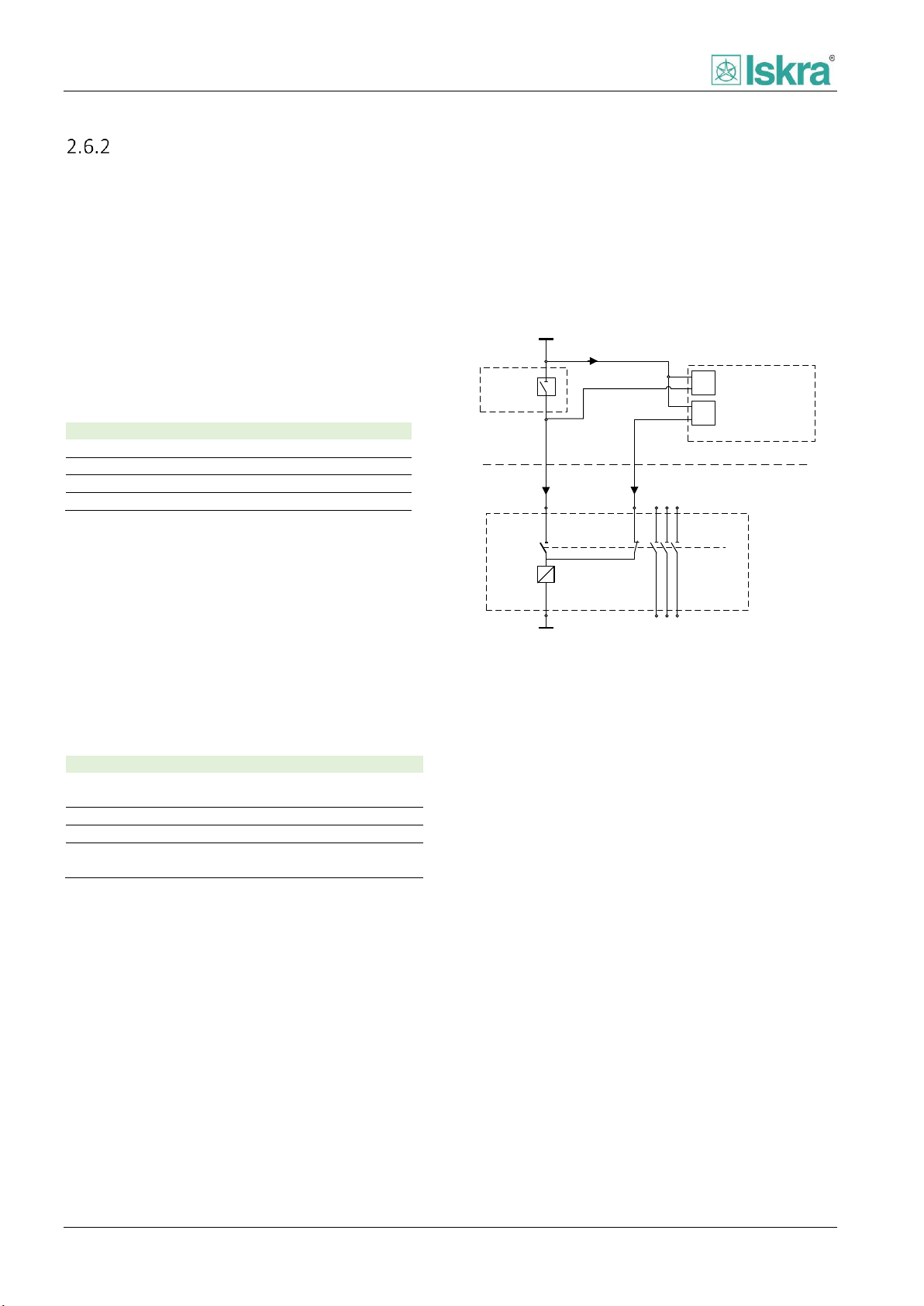
Functionality
Mode
Mode 1
Uses CB status for TCS function.
Mode 2
Uses CB status plus one additional digital input.
Mode 3
TCS using external resistor.
Mode 4
TCS without using external resistor.
CB closed
CB open
Alarm
0 0 After the Delay00 time
elapses.
0 1 Off. 1 0
Off.
1 1 After the Delay00 time
elapses.
Trip Coil
DI1
DI2
+
+
-
-
ITCS
ITCS2ITCS1
FPC
Circuit
breaker
Trip
contact
CB closed
CB open
Relay compartment
Circuit breaker compartment
L+/L1
L-/N
Trip circuit supervision - ANSI 74 - TCS
Trip circuit supervision function (TCS) is designed for surveillance of breaker control circuits.
2.6.2.1 Functionality
Function is executed autonomously by the device. Two
digital galvanic isolated inputs are used. The result of
Trip circuit supervision function is a signal that can be
used to activate digital output. The signal can also be
accessed using the communication protocol. The
function itself has different operating modes each using
its own connection scheme and alarm status trigger.
Table 58: Basic description of TCS module functionalities.
2.6.2.2 Mode 1
Mode 1 is considered basic TCS operation. TCS state is
valid if exactly one of the Input TCS 1 or TCS 2 has value
1. Invalid states are 00 and 11. For each of invalid states
a delay is set. After corresponding delay elapses the TCS
wrong position signal is stated.
contact to circuit breaker compartment. Scheme can be
found on Figure 2.39
Figure 2.39 Trip circuit supervision with two digital inputs and
function of monitoring circuit breaker position.
Table 59: TCS function response according to inputs using
Mode 1 setting.
The benefit of using two digital inputs is that only two
digital inputs are used to indicate status of circuit
breaker and monitor the trip circuit. There is also no
need of external resistor to be used. It has to be taken in
to account that, when circuit breaker is in open position
trip circuit supervision does not monitor line from trip
66 USER MANUAL FPC 200 - 3/2017

Functionality
CB open
TCS 1
Alarm
0 0 After the Delay00 time elapses.
0 1 Off.
1 0 Off.
1 1 Off.
Trip Coil
DI1
DI2
+
+
-
-
ITCS
ITCS
ITCS
FPC
Circuit
breaker
Trip
contact
CB closed
TCS 1
DI3
+
-
CB open
ITCS2
I52b
Relay compartment
Circuit breaker compartment
L+/L1
L-/N
L+/L1
L-/N
Please note that a trip line inside the trip
contact compartment (example can be
seen on Figure 2.40) cannot be supervised
using any of the schemes mentioned in this
section.
TCS 1
Alarm
0
After the Delay00 time elapses
1
Off
Trip Coil
DI1
DI2
+
+
-
-
I52a
I52b
FPC
Circuit
breaker
Rext
DI3
+
-
ITCS
ITCS
TCS 1
Trip
contact
CB closed 52a
CB open 52b
Relay compartment
Circuit breaker compartment
L-/N
L+/L1
L+/L1
L-/N
Type
L+/L1 [V]
R
ext
[kΩ]
P [W]
DC
24
1
≥3
DC
48
27
DC
60
39
DC
110
82
DC
125
100
DC
220
200
AC
230
200
2.6.2.3 Mode 2
In order to supervise section between trip contact
compartment and circuit breaker compartment when
CB is in open position, a control diagram used in Mode 2
[Figure 2.40] can be used by adding two additional wires
to circuit breaker compartment.
It should be noted that by using this scheme, both of
trip circuit supervision digital inputs are connected in
serial. The case occurs when circuit breaker is in open
position and none of trip contacts is active. This
situation will result in a valid position when both of the
contacts are active.
Table 60: TCS function response according to inputs using
Mode 2 setting.
2.6.2.4 Mode 3
Mode 3 is a single TCS input mode. The benefit of using
one digital input is that no additional wiring from the
device to the circuit breaker compartment is needed. It
should be noted that by using this scheme an additional
external resistor is needed. By using the resistor a trip
circuit is supervised in closed and opened position of CB.
Table 61: TCS function response according to inputs using
Mode 3 setting.
Figure 2.40 Trip circuit supervision with two digital inputs
tailored for full line control of trip circuit in both positions of
circuit breaker. The diagram also implies aditional digital input
to be used as circuit breaker closed position.
USER MANUAL FPC 200 - 3/2017 67
Figure 2.41 Trip circuit supervision using only one digital input
and external resistor. The diagram also implies connection of
circuit breaker status.
2.6.2.4.1 External resistor estimation
Estimated external resistor R
value is determined in
ext
the table below.
Figure 42 External resistor values depending on voltage level.

Functionality
CB position
TCS 1
Alarm
Opened
0 Off.
Opened
1 Off.
Closed
0 After the Delay00 time elapses.
Closed
1 Off.
Unknown
0 After the Delay00 time elapses.
Unknown
1 Off.
Trip Coil
DI1
DI2
+
+
-
-
I52a
I52b
FPC
Circuit
breaker
DI3
+
-
ITCS1
ITCS1
TCS 1
Trip
contact
CB closed 52a
CB open 52b
Relay compartment
Circuit breaker compartment
L+/L1
L+/L1
L-/N
L-/N
Parameter
Range
Description
Enabled
No
Yes
Enabling supervision function.
Delay00
0 … 1000 … 60000 ms
Delay of 00 state alarm.
Delay11
0 … 1000 … 10000 ms
Delay of 11 state alarm, inhibited if Allow position 11 is enabled.
Mode
1. Mode 1
I1OP+TC, I2CL+TC
2. Mode 2
I1OP, I2CL+TC, I3TC
3. Mode 3
I1OP, I2CL, I3TC+ER
4. Mode 4
I1OP, I2CL, I3TC
Activation of TCS blocking when CB is in closed position.
Name
Description
TCS alarm
Total consecutive number of TCS alarm signals.
2.6.2.5 Mode 4
Mode 4 is a single TCS input mode without using
external resistor. A trip circuit is supervised only by
circuit breaker being in closed position. The scheme of
such case can be seen on Figure 2.43.
Table 62: TCS function response according to inputs using
Mode 4 setting.
2.6.2.6 Setting parameters
Table 63: TCS function parameters.
Figure 2.43 Trip circuit supervision using only one digital input
without external resistor. The diagram also implies connection
of circuit breaker status.
2.6.2.7 Counters
Table 64: Counter presented in TCS.
68 USER MANUAL FPC 200 - 3/2017

Functionality
Trip
Close command
1.st dead time
ARC not ready
2.nd dead time
Max. pulse
Reclaim
time
Reclaim time
ARC in progress
Max. pulse
CB open
Manual closing
Trip
Close command
1.st dead time
ARC not ready
Reclaim
time
ARC in progress
Max. pulse
Definite trip blocked
CB open
Manual closing
Block delay
Auto-reclosing function - ANSI 79 - AR
Approximately 85 % of all faults occurring at overhead lines have temporary short circuit character. After protection
operation they usually disappear. Line is switched back into operation the moment when fault is not present anymore
and any delay runs out. Reclosing is executed with auto-reclosing function. If the fault is still present after reclosing the
protection function will operate again. Based on setting the process of reclosing can repeat several times.
2.6.3.1 Functionality
The auto-reclosing function (AR) can be used with any
circuit breaker suitable for auto reclosing. Four
programmable AR shots are provided. Combined with
dead time duration user can form a scenario which will
be executed in case of fault occurrence.
Auto reclose function is set in standby mode when it is
enabled and no blocking or trip signals are present. The
function monitors trip signals. When any of them is
triggered the function operates according to defined
scenario.
Figure 2.44: Automatic reclosing successful in second attempt.
In case when the last auto-reclosing shot is still
unsuccessful a final trip order is given and AR function is
blocked until circuit breaker close command is initiated.
Reclosing is considered successful when no trip signal
appears after reclosing during the Reclaim time (Figure
2.44). In case of dynamic blocking, scenario is reset after
one second delay. In case of fault appearing before
reclaim time has passed AR function will continue with
next cycle if any left.
Figure 2.45: Unsuccessful automatic reclosing, dynamic block.
USER MANUAL FPC 200 - 3/2017 69

Functionality
Parameter
Range
Description
Enabled
No
Yes
Enabling function.
Reclaim time
0,5 … 3,0 … 300,0 s
Time after the last AR closing without a new Trip. Reclosing is successful when
time elapses.
Maximal dead time
0,00 … 60 s
Number of cycles
0 … 1 … 3
Number of active AR cycles.
1st dead time
0,00 … 300,00 s
Dead time of the 1st cycle.
2nd dead time
0,00 … 300,00 s
Dead time of the 2nd cycle.
3rd dead time
0,00 … 300,00 s
Dead time of the 3rd cycle.
50/51-1
No
Yes
Tripping of this protection will trigger AR cycle
50/51-2
No
Yes
Tripping of this protection will trigger AR cycle
50/51-3
No
Yes
Tripping of this protection will trigger AR cycle
50/51-4
No
Yes
Tripping of this protection will trigger AR cycle
50N/51N-1
No
Yes
Tripping of this protection will trigger AR cycle
50N/51N-2
No
Yes
Tripping of this protection will trigger AR cycle
50N/51N-3
No
Yes
Tripping of this protection will trigger AR cycle
50N/51N-4
No
Yes
Tripping of this protection will trigger AR cycle
Manual Close
No
Yes
Tripping of this protection will trigger AR cycle
Manual close block
time
0,20 … 1,00 … 300,00
s
Time after CB is manually closed when the AR is in the block state.
Input
None
Variable 1
Variable 2
Variable 3
Variable 4
2.6.3.2 Blocking
Two blocking types are included in AR function. Autoreclosing function is deactivated when any blocking is
set (Figure 2.45).
2.6.3.2.1 Static blocking
Following conditions block AR function during standby
mode:
External digital input AR static block is active
Circuit breaker not in closed position
Switchgear-related fault
2.6.3.3 Setting parameters
2.6.3.2.2 Dynamic blocking
Following conditions block AR when function is in
progress:
Manual close or open command is issued
First time switching the breaker on for the
duration of Manual close block time to avoid
operating in switch-on-fault condition.
Switchgear-related fault
External digital input AR dynamic block is
active
Table 65: Auto-reclosing function parameters.
70 USER MANUAL FPC 200 - 3/2017

Functionality
Constant
Value
Description
Max trip time
1 s
Maximum duration when trip signal can be present. Dynamic block is set if trip
signal duration exceeds Max trip time.
Block delay
1 s
Blocking time after dynamic blocking conditions occur. Standby conditions are
checked when Block delay time elapses.
Maximum close pulse
time
0,3 s
Maximum duration of Close command output pulse.
Name
Description
1st cycle
Consecutive number of active first cycles of the function.
2nd cycle
Consecutive number of active second cycles of the function.
3rd cycle
Consecutive number of active third cycles of the function.
Define trip
Consecutive number of
2.6.3.4 Predefined values
Table 66: Auto-reclosing function predefined values.
2.6.3.5 Counters
Table 67 Counters presented auto-reclosing function.
USER MANUAL FPC 200 - 3/2017 71

Functionality
MC-Machine control
Service factor:
ON
1,15In
Stall current:
4,00In
COUNTERS
Running hours:
Running minutes:
4442
51
Machine control
Status:
Running
Running Time:
204h 57min
Machine control
2.6.4.1 Description
Machine control is a control function which includes
basic parameters of rotating machine used for
calculation of rotation status and operating time of
machine.
Figure 2.46 Wiring scheme of voltage measurement
transformers.
2.6.4.2 Operation
Machine control constantly calculates rotation status of
machine. The function distinguish between six different
states of rotating machine:
Stopped
Starting
Normal operation
Overload
Re-acceleration
Stalling
Functions as Starts per hour [2.5.5] and Locked rotor
[2.5.4] than uses information about rotation status to
ensure correct function operation.
2.6.4.3.2 Starting
State can be active if previous state was stopped and at
least one of the phase currents exceeds Service factor
level of In.
2.6.4.3.3 Normal operation
State is active if all of the currents are below Service
factor and above 5 % of In.
2.6.4.3.4 Overload
Overload state is considered if previous state was
normal operation and one of phase currents exceeds
Service factor level of In.
2.6.4.3.5 Re - acceleration
Re-acceleration is considered if previous state was
Normal operation or Overload and one of phase
currents exceeds Service factor level of In, while reacceleration digital input is active.
2.6.4.3.6 Stalling
Stall state is considered if previous state was Overload
and one of phase currents exceeds Stall current level of
In.
2.6.4.4 Accessibility
Current status of rotating machine can be accessed
using LEDs, Digital relay outputs, communication, pc
software MiQen and it can also be accessed via
diagnostic on HMI:
2.6.4.3 Status detection
2.6.4.3.1 Stopped
Rotational machine is considered stopped when all of
the currents are below 5 % of I
amount of time.
72 USER MANUAL FPC 200 - 3/2017
for at least brief
n_obj
Figure 2.47 Diagnostic screen of rotating machine.

Functionality
Parameter
Range
Description
Service factor
0,50 … 1,15 … 4,00 In
Service factor of rotating machine.
Stall current
0,50 … 4,00 … 10,00 In
Current limit above which stall of the rotating machine is considered.
Name
Description
Running hours
Number of running hours of a rotating machine.
Running minutes
Number of running minutes of one hour of a rotating machine.
2.6.4.5 Setting parameters
Table 68 Machine control function parameters.
2.6.4.6 Counters
Table 69 Counters presented in machine control function.
USER MANUAL FPC 200 - 3/2017 73

Functionality
Parameter
Range
Description
Enabled
No
Yes
Enabling protection function.
Operate mode
Off
On
Enabling protection function separately for each group level.
Trip delay
0,00 … 1,00 … 300,00 s
Delay of trip signal.
Pickup delay
0 … 5 … 1000 ms
Time stabilization of fault detection. As a filter of short disturbances on
measuring circuits. Time before protection starts.
Drop-out delay
0,00 … 0,20 … 60,00 s
Time stabilization of pickup signal. Time when the monitored value is
outside the operating range, but the protection does not stop yet.
Pickup block
None
Variable 1
Variable 2
Variable 3
Variable 4
Source of blocking signal.
Digital input
Description
External trigger 1
External trigger of External trip 1 protection.
External trigger 2
External trigger of External trip 2 protection.
Name
Description
Pickup
Total consecutive number of pickup signals.
Trip
Consecutive number of trip signals.
External trip – EXT-T
External trip function is one of the basics functions of the device. The function is triggered on external signal.
2.6.5.1 Functionality
By using External trip function it is possible to use a
custom binary signal to trigger digital input. A function
than set pickup and trip signal according to user defined
settings. By using protection trip signal it is possible to
trigger a trip of circuit breaker or to associate it to a
desired output relay or LED of protective device.
2.6.5.2 Measurements
The function pickup is triggered by dedicated digital
input signal.
2.6.5.5 Setting parameters
2.6.5.3 Delays
Function includes following delays explained in Chapter
2.1:
Pickup delay
Trip delay
Drop-out delay
2.6.5.4 Block settings
Pickup of any instance separately of protection can be
individually blocked by any user defined signal [2.6.5.].
Table 70 External trip function parameters.
2.6.5.6 Associated digital inputs
Table 71 Selectable digital inputs of the function.
2.6.5.7 Counters
74 USER MANUAL FPC 200 - 3/2017

Functionality
Signal name
Short name
Variable 1
Var1
Variable 2
Var2
Variable 3
Var3
Variable 4
Var4
Maximum number of inputs any of the
variable takes in to account is 10.
Var2
Var1
Relay on command
Var4
Relays:
Variable 3
T C C 4 5 R 7 8
Var3
A
A
Parameter
Range
Description
Enabled
Yes
No
Enabling function.
Function
Or
Nor
And
Nand
Function a variable is using to calculate the result of the selected input
signals.
Signals
DI 1 … 10
List of DI signals used in calculation of the function. The list is controlled
by user selected ticks for each DI respectively.
2.7 User defined signals
Description
User defined signals are signals used to associate digital
inputs to digital outputs. There are several different user
defined signals which can be activated by custom
assigned digital inputs. Each custom defined signal can
be assigned to multiple digital inputs and output
variable is a result of one of selected OR, AND, NOR or
NAND function that carries out across them.
Table 72 Names of variables.
Assigning user defined signals to
digital outputs
State of each variable can be independently
assigned to any available output relay or LED
[4.2.4.5, Digital outputs].
Figure 2.48 User defined signals can be assigned to various
output relays or LEDs.
Blocking of individual protection
Each user defined signal can be used as a blocking signal
to inhibit individual protection or control function.
Inhibition will be active as long as the signal is present.
2.7.3.1 Setting parameters
Table 73 External trip function parameters.
Example for overcurrent protection can be found in
each parameters section of Functions [Chapter 2].
USER MANUAL FPC 200 - 3/2017 75

Functionality
All recorded digital input and output
signals are presented in positive logic
regardless of individual binary signal logic
setting.
2.8 Disturbance recording
Description
Disturbance recording function is used to record analog
and binary values intended for post fault analysis.
Disturbance records are saved in non-volatile device
memory and can be read and analysed using USB
memory stick. The device can hold up to 127
disturbance records, with user definable sample rate
and pretrigger record time. In the device records are
sorted by date of trigger occurred.
Figure 2.49: Disturbance recording saved as COMTRADE
format and visualized with fault analysis software.
data a separate folder named by serial number is
created on USB stick by the device. In the created folder
records are named by the following mask: year, month,
day, hour, minute, second, millisecond and name of the
trigger.
Trigger
Trigger purpose is to activate record of disturbance
record. It can be set through corresponding menu and
includes, defined by user: Any trip signals, any pickup
signals and all individual digital outputs and inputs
respectively.
Recorded data
There are four separate channels reserved for analog
values, dedicated to record AI measurement values.
Based on a device type a current or voltage values are
stored. In addition the binary signals of functions,
protections, digital outputs and digital inputs in the
device are also recorded. Additionally to achieve better
transparency of the disturbance data only enabled
functions and protection functions are recorded.
USB stick
The records can be transferred to USB stick separately
or altogether. They can be transferred from device as
standard COMTRADE file and reviewed in third party
software. For purpose of transparency of the stored
Clearing disturbance records
Disturbance records can be manually cleared using
Reset/Clear menu [4.2.4.6].
76 USER MANUAL FPC 200 - 3/2017

Functionality
Parameter
Range
Description
Control parameters
Sample rate
400 Hz
800 Hz
1600 Hz
3200 Hz
Data recording sample rate. The setting effects on duration of the record.
Duration
(depends on
sample rate setting)
5120 ms
2560 ms
1280 ms
640 ms
Record duration calculated based on selected sample rate. Duration is
informative and not user definable parameter.
Pretrigger
0 … 25 … 100 %
Time in percent of total duration of the record, that presents the fault
recorded before actual trigger.
Triggers
Pickup
Yes
No
Enabling trigger on appearance of any trip signal.
Trip
Yes
No
Enabling trigger on appearance of any pickup signal.
DO 1 … 8
Yes
No
Enabling trigger on signal dedicated to activate user defined DO
respectively.
DI 1 … 10
Yes
No
Enabling trigger on activated DI signal respectively.
Setting parameters
Table 74 Disturbance recording function parameters.
USER MANUAL FPC 200 - 3/2017 77
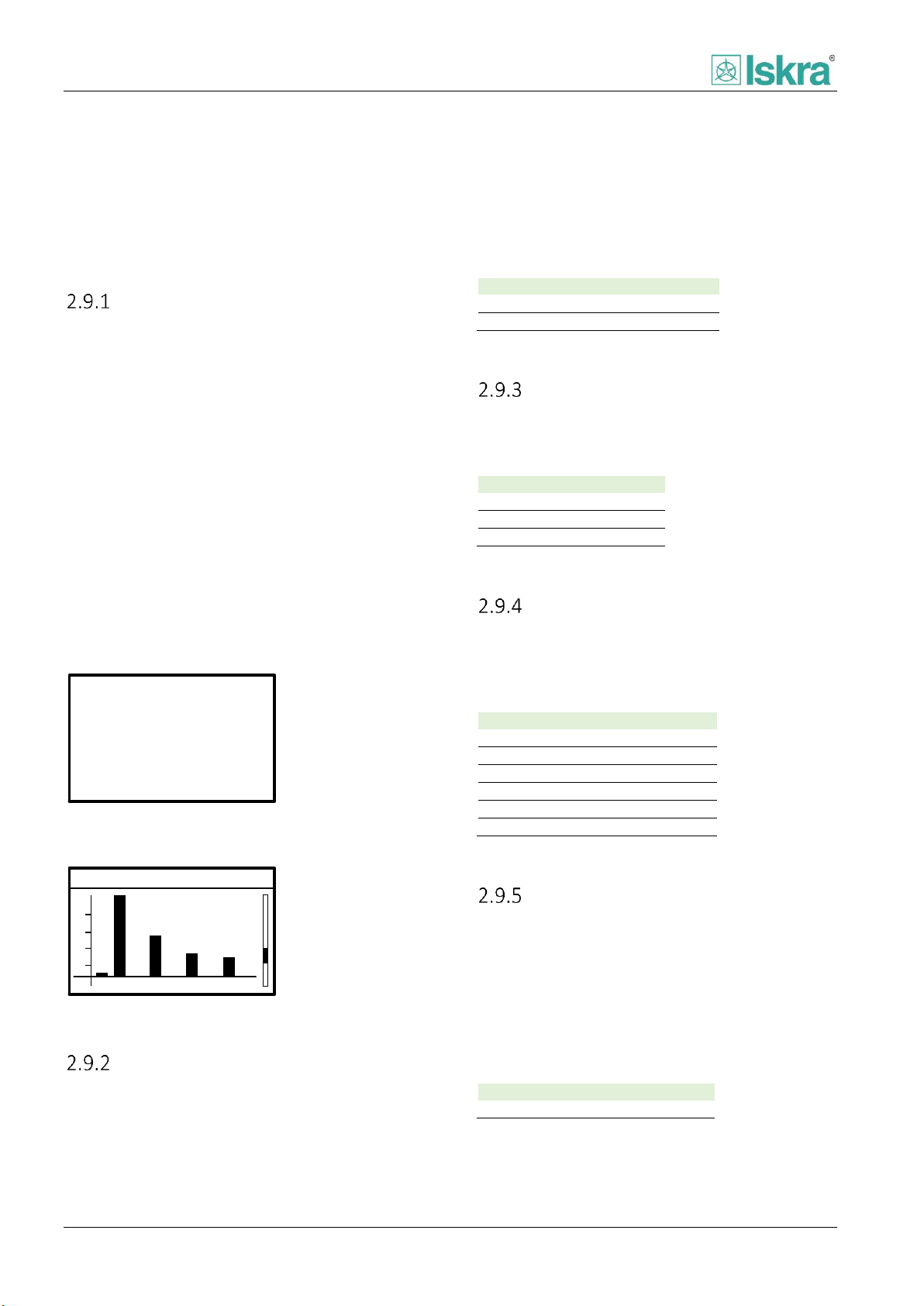
Functionality
A
A
A
A
128.4
135.6
132.4
5.2
IL2RMS=
IL3RMS=
IeRMS=
IL1RMS=
Harmonics
2 3 4 5 6 7 8 9
%
3
1
2
4
THD=6%
IL1=235A
f=50Hz
Analog value
Description
In
Nominal device current
Un
Nominal device voltage
Analog value
Description
IL1
Phase current
IL2
Phase current
IL3
Phase current
Analog value
Description
UL1
Phase voltage
UL2
Phase voltage
UL3
Phase voltage
U12
Phase to phase voltage
U23
Phase to phase voltage
U31
Phase to phase voltage
Analog value
Description
f
Device base frequency
2.9 Measurements
Measurement values can be accessed by reading it via communication [3.1.7.3] or by accessing them using
dedicated PC based software [4.3.2.4] or by using local HMI [4.2.4.2].
Presented measured values
Device is able to measure currents or voltages.
According to model measurement card consist of four
analog measured values. Device measures and
calculates presented values of currents or voltages and
displays them. Measurements are presented in:
RMS,
average RMS in user defined interval cycle
time,
peak of average RMS,
RMS in bar maximum 150 % of
separate harmonics up to 9
harmonics presented in percent of RMS value
in bars separately,
phase unbalance,
frequency.
,
th
harmonic,
Table 75 Nominal values of the device.
Current measurement
The value of each of phase currents and earth current is
acquired through dedicated input current transformer.
Table 76 Measured current values.
Voltage measurement
The value of each of phase to phase voltages is
calculated through measured phase voltages of
measurement voltage transformers.
Figure 2.50Example of current measurement screen as seen on
HMI.
Figure 2.51 Example of harmonics overview as seen on HMI.
Nominal values
Nominal values Un and In are calculated based on user
defined settings in analog inputs section [4.2.4.5.4].
78 USER MANUAL FPC 200 - 3/2017
Table 77 Measured voltages values.
Frequency measurement
Frequency is determined based on healthy analog
acquisition line measurement with priority of phase
voltage measurements first, than phase current
measurements. In addition the healthy line is
considered as a line which value is nearest to Un or In.
Device frequency determines FFT window length to be
used in exact device measurement of analog values.
Table 78 Frequency value.

Functionality
Analog value
Description
I1
Positive sequence
I2
Negative sequence
I0
Zero sequence
3I0
three times zero sequence
U1
Positive sequence
U2
Negative sequence
U0
Zero sequence
3U0
three times zero sequence
RTD type
Pt100
Temperature
limit
Temperature
Lower
-50 °C
Upper
250 °C
Detection of open probe
contacts
Detection of short circuit
probe contacts
1: 24°C
2: 24°C
3: 24°C
4: 24°C
5: 24°C
6: 24°C
7:N/A°C
8:---°C
Current temp. 1-8
7:N/A°C
8:---°C
Symmetrical components
By using three symmetrical systems any three-phase
non-symmetrical system can be presented. These
systems are named positive negative and zero sequence
systems:
Positive sequence indicates rotating magnetic
field in native direction. In fully symmetrical
three phase system only positive sequence is
present while negative and zero sequence
have zero value.
Negative sequence value indicates presence
of rotating magnetic field in opposite direction
than native direction of three phase system.
Zero sequence is present if three-phase system
is not balanced
using 3-wire connection type to temperature sensors.
The measured temperatures are updated each second.
Following RTD type is supported:
Table 80 Type of supported RTD.
2.9.7.1 Minimum and maximum measured
values
Each probe has a lower and upper limit, indicating
malfunction of probe if the measured temperature
exceeds this limits. If any limit is exceeded a dedicated
sign is presented on HMI. In addition average, maximal,
and minimal temperature can be accessed for each
individual probe.
Table 79 Symmetrical components values.
Temperature
Measurement is performed by using appropriate
external module [5.6.1]. Specific algorithms are used to
interpret measurement of probes resistance. RTDs are
Table 81 Maximum and minimum limits of temperature
measurement.
Figure 2.52 Temperature measurement as presented on HMI. If
any temperature limit is exceeded a dedicated sign is
presented.
USER MANUAL FPC 200 - 3/2017 79

Functionality
Operating state
Description
Output signal
Protection functions
Normal state
FPC 200 is fully operational
- Ready LED ON
- Ready relay ON
- All functions are operating
Error state
Fault is detected.
If internal fault is eliminated in
5 s time, device returns to
Normal state.
- Blinking Ready LED
- Continuous sound beeping
- System status register = 1
- HMI is displaying internal
fault
- Protection functions are blocked.
- Output relays are blocked.
Confirmed error state
Fault is detected and manually
confirmed.
- Blinking Ready LED
- System status register = 1
- Protection functions are blocked.
- Output relays are blocked
Error detection
Restart
Restart = 2x
Manual confirmation
Normal state
Error state
Confirmed
error state
Software
internal fault
Hardware
internal fault
Internal fault
eliminated in 5s
2.10 Self-diagnostic
Several self-monitoring functions run continuously to check the operation of hardware and software while device is in
service. Device status is represented by internal watchdog that can be connected to Ready Relay output via Relay
mapping menu. Digital output 6 can be set to operate as ready relay as it is designed to operate as such. FPC 200
distinguish between two major types of internal faults:
Hardware internal faults
Software internal faults
System status register
System status register is a 16 bit memory register dedicated to correspond with specific internal fault type. It is possible
to access this register by Modbus RTU. Internal fault is detected if value of stored bit is equal to 1.
Operating states
Three operating states are used to increase reliability of protection relay self-diagnosis. According to internal fault type,
the device will start to function in designated operating state.
Table 82 Operating states of the device.
Figure 2.53 Diagram of FPC 200 self-diagnostic error detection
80 USER MANUAL FPC 200 - 3/2017

Functionality
Hardware internal faults
Display massage
System status register bit
External RTC not responding
EXT clock error
125.0
Internal RTC not responding
INT clock error
125.1
EEPROM for settings not responding
Memory 1 error
125.2
EEPROM on AI card not responding
AI card error 2
125.3
MRAM not responding
Memory 2 error
125.4
eMMC not responding
Memory 3 error
125.5
CPU powered from USB port, main power disconnected
Main power off
125.6
ADC on AI card not responding
AI card error 1
125.7
PS-DO card not responding
DO card error
125.8
DIO card not responding
DIO card 1 error
125.9
CPU on AO card not responding
AO card error
125.12
Software internal faults
RT module not responding
RT error
125.13
NRT module not responding
NRT error
125.14
Internal faults description
Description of specific faults can be found in the table below.
Table 83 Internal faults description.
USER MANUAL FPC 200 - 3/2017 81

Communication
Bit information
Character frame
Start
bit
Data
bits
Parity
bit
Stop
bits
IdleIdle
Modbus PDU format
2 - 5
Function code (8 bits)
Data (0 to n bytes)
3 Communication
FPC 200 can be connected to supervision communication network based on following communication protocols:
Modbus RTU
IEC60870-5-103
3.1 Modbus RTU
General description
Modbus communication protocol uses request-reply
logic to obtain information from dedicated devices. The
device that executes request is always a master and
device that listens to request is always a slave. Modbus
protocol allows several slave devices to be connected to
a single master device. Individual devices are addressed
by a specific code unique to each slave device
connected to communication network. FPC 200 is
always a slave station and it allows to be connected to
any other device with Modbus master communication
channel.
Table 84 Modbus PDU format.
Modbus function supported
Modbus protocol uses standard set of functions.
Functions are divided by the ability to read or write one
or multiple data bits.
3.1.3.1 Read functions:
Modbus PDU (protocol data unit)
Every Modbus character frame send or received consists
two fields which assign function code being used and
data being transferred. The total number of data bits to
be transferred in one package is dependent of the
transfer function to be used. If there was no error
during transmission of data function codes in request
and reply are identical. There are two types of data that
can be transmitted, bits (also called Coils) and 16 bit
words (also called Registers). Words used to transfer
data are always represented in big-endian format.
Figure 54 Modbus RTU character frame
Function 2: reading of n input bits
Function 3: reading of n output or internal bits
Function 4: reading of n input words
3.1.3.2 Write functions:
Function 5: writing of 1 bit
Function 6: writing of 1 word
Function 16: writing of n words
Time synchronization
Time synchronization zone is dedicated to set exact time
to the device. To write time massage function 16
containing 4 words should be used. Reading device time
massages can be done separately word by word, or by
using a multiple words function 3 can be used to access
whole timestamp instead. It is possible that internal
clock could drift over time. To ensure that device
internal time is set correctly, time synchronization
should be carried out over regular intervals of 10 to 60
82 USER MANUAL FPC 200 - 3/2017

Communication
Word
Most significant byte
Least significant byte
1
0
Year: 0 … 99
2
Month: 1 … 12
Day: 1 … 31
3
Hour: 1 … 23
Minute: 0 … 59
4
Millisecond: 0 … 59999
Word
Control word structure
Most significant byte
Least significant byte
1
Number of transaction: 0
… 255
Number of events: 0
… 4
Word
Single event structure
Most significant byte
Least significant byte
1
Type of event: 08
Type of event: 00
2
Address: 1 … 65535
3
00
00 4 00
Value: 0 … 3
5
0
Year: 0 … 99
6
Month: 1 … 12
Day: 1 … 31
7
Hour: 1 … 23
Minute: 0 … 59
8
Millisecond: 0 … 59999
The clock synchronization sending
telegram interval should be more than 30
sec apart.
s. If device receives no time synchronization massage for
300 s the event Time not sync is triggered.
Internal clock is written according to IEC 60870-5-4,
Binary Time 2a standard and consists of 8 characters
structure:
Table 85 Communication telegram structure of time
synchronization.
Events
3.1.5.1 Time tagging of events
For purpose of transparency of the data processed by
FPC 200, the device uses time tagging function to
timestamp specific events that occurred during its
operation. Therefore chronological order of events can
be maintained accurately. Internal time is used when
device time tags the event.
All the events that are recorded in device are available
over Modbus communication with two internal storage
queues of total 100 stored events.
- Value of the event
Table 86 Event reading communication telegram structure.
3.1.5.3 Reading of events
Monitoring system periodically reads the control word
and checks whether there are new events available.
Only reading of control word is allowed or reading of
the whole 33 word block. For all other requests, the
device returns an error (Wrong data).
On the arrival of new events in the buffer, the device
writes the values of events into the structure in the
analogue table and increases the number of
transactions in the control word by 1 and sets the
number of written events (maximum 4).
Monitoring system reads the values of the events,
checks for any reception errors and validity of the data.
If events are present, device stops to write new events
in the buffer and waits for confirmation for those that
were sent last.
3.1.5.2 Structure
The device presents up to four events at the same time
for each buffer and one control word. Structure of data
in the table looks as follows:
Control word + Event 1 + Event 2 + Event 3 + Event 4
The function of control word is to ensure correct
reception of all data, even in case of trouble and loss of
data at communication. To ensure this, it includes
number of transactions and number of events. On
device boot, number of transactions is 0.
Events are recorded in 8 word structure. Each event
consists of the following information:
- Address where the data is stored
- Exact time of the event
USER MANUAL FPC 200 - 3/2017 83
Monitoring system confirms correct reception to device
with writing into control word the same transaction
number and number of events is reset to 0.
Upon confirmation of successful reception from the
monitoring system, the device erases the transferred
events from buffer, in analog table all words for the
events are set to 0, writes new events and sets a new
control word, as previously described. Deletion of
events is only allowed if a request to read the entire
block of events has previously been issued. Namely, the
monitoring system can’t confirm events, if it did not
read them previously.
When device sends all events and clears its buffer, it
does not change the control word anymore even after
the monitoring system reads the control word.

Communication
Parameter
Range
Description
Protocol
Modbus RTU
IEC103
Selection of active communication protocol.
Device address
0 … 33 … 247
Number by each slave device is uniquely addressed.
Baud rate
1200
2400
4800
9600
19200
38400
57600
115200
Defines the number of binary information to be transmitted per second.
Parity
None
Odd
Even
Adds an error checking bit that follows the data bits in the character
frame.
Stop bits
1 2 Number of stop bits after each character frame.
Data bits
8 9 Number of data bits in each character frame.
3.1.5.4 Remote deletion of events
set to FF. In this case, the number of transactions is
reset to 0.
Monitoring system has the ability to delete all events in
the device, in the buffer and in the analogue table, by
writing control word which has the number of events
Parameters
The following parameters needs to be set for the communication to be established properly
Table 87 Parameters of Modbus RTU communication protocol.
84 USER MANUAL FPC 200 - 3/2017

Communication
Type
Word address (0x)
Access
Time synchronization
10 - 13
R/W
Year
10
R/W
Month + Day
11
R/W
Hour + Minute
12
R/W
Milliseconds
13
R/W
Events 1
10 - 29
R/W
Exchange word
10
R/W
Event 1
11
R
Event 2
19 R Event 3
21
R
Event 4
29
R
Events 2
40 - 59
R/W
Exchange word
40
R/W
Event 1
41
R
Event 2
49 R Event 3
51
R
Event 4
59
R
Trip signals
120
R
Protection OC1 [50/51 - 1]
120.0
R
Protection OC2 [50/51 - 2]
120.1
R
Protection OC3 [50/51 - 3]
120.2
R
Protection OC4 [50/51 - 4]
120.3
R
Protection OCE 1 [50NG/51NG - 1]
120.4
R
Protection OCE 2 [50NG/51NG - 2]
120.5
R
Protection OCE 3 [50NG/51NG - 3]
120.6
R
Protection OCE 4 [50NG/51NG - 4]
120.7
R
Protection REF 1 [64REF - 1]
120.8
R
Protection REF 2 [64REF - 2]
120.9
R
Protection NS [46]
120.10
R
Reserved
120.11
R
Protection UC [37]
120.12
R
Reserved
120.13
R
Protection UV 1 [27 - 1]
120.14
R
Protection UV 2 [27 - 2]
120.15
R
Address table
3.1.7.1 Status and control
Table 88 Modbus communication table.
USER MANUAL FPC 200 - 3/2017 85

Communication
Trip signals
121
R
Protection RUV [27R]
121.0
R
Protection PSUV 1 [27D - 1]
121.1
R
Protection PSUV 2 [27D - 2]
121.2
R
Protection OV 1 [59 - 1]
121.3
R
Protection OV 2 [59 - 2]
121.4
R
Protection NVD 1 [59NG - 1]
121.5
R
Protection NVD 2 [59NG - 2]
121.6
R
Reserved
121.7
R
Reserved
121.8
R
Protection OF 1 [81H - 1]
122.9
R
Protection OF 2 [81H - 2]
122.10
R
Protection UF 1 [81L - 1]
122.11
R
Protection UF 2 [81L - 2]
122.12
R
Reserved
122.13
R
Reserved
122.14
R
Protection TO [49T]
122.15
R
Trip signals
122
R
Protection MTO [49M]
122.0
R
Protection LR [48/51LR/14]
122.1
R
Protection SPH [66]
122.2
R
Protection EXT 1
122.3
R
Protection EXT 2
122.4
R
Thermostat 1
122.5
R
Thermostat 2
122.6
R
Buchholz 1
122.7
R
Buchholz 2
122.8
R
Protection ROCOF [81R]
122.9
R
Protection TMO 1 [38/49T - 1]
122.10
R
Protection TMO 2 [38/49T - 2]
122.11
R
Protection TMO 3 [38/49T - 3]
122.12
R
Protection TMO 4 [38/49T - 4]
122.13
R
Protection TMO 5 [38/49T - 5]
122.14
R
Protection TMO 6 [38/49T - 6]
122.15
R
Trip signals
123
R
Protection TMO 7 [38/49T - 7]
123.0
R
Protection TMO 8 [38/49T - 8]
123.1
R
Protection TMO 9 [38/49T - 9]
123.2
R
Protection TMO 10 [38/49T - 10]
123.4
R
Protection TMO 11 [38/49T - 11]
123.5
R
Protection TMO 12 [38/49T - 12]
123.6
R
Protection TMO 13 [38/49T - 13]
123.7
R
Protection TMO 14 [38/49T - 14]
123.8
R
Protection TMO 15 [38/49T - 15]
123.9
R
Protection TMO 16 [38/49T - 16]
123.10
R
Table 89 Modbus communication table.
86 USER MANUAL FPC 200 - 3/2017

Communication
Type
Word address (0x)
Access
Digital inputs
124
R
Digital input 1
124.0
R
Digital input 2
124.1
R
Digital input 3
124.2
R
Digital input 4
124.3
R
Digital input 5
124.4
R
Digital input 6
124.5
R
Digital input 7
124.6
R
Digital input 8
124.7
R
Digital input 9
124.8
R
Digital input 10
124.9
R
Device status
125
R
Device error
125.0
R
Device ready
125.1
R
Time not sync
125.2
R
System status
126 R EXT clock error
126.0
R
INT clock error
126.1
R
Memory 1 error
126.2
R
AI card error 2
126.3
R
Memory 2 error
126.4
R
Memory 3 error
126.5
R
Main power off
126.6
R
AI card error 1
126.7
R
DO card error
126.8
R
DIO card 1 error
126.9
R
AO card error
126.12
R
RT error
126.13
R
NRT error
126.14
R
Control status
127
R
Setting group
127.0
R
CB open status
127.1
R
CB close status
127.2
R
CB status alarm
127.3
R
CB command failed
127.4
R
CB command successful
127.5
R
AR not ready
127.6
R
AR Blocked
127.7
R
AR Static block
127.8
R
AR Dynamic block
127.9
R
Table 90 Modbus communication table.
USER MANUAL FPC 200 - 3/2017 87

Communication
Type
Word address (0x)
Access
Remote control
12C
W
CB Open
12C.0
W
CB Close
12C.1
W
Settings group A
12C.2
W
Settings group B
12C.3
W
Local mode
12C.4
W
Remote mode
12C.5
W
Confirm alarms
12C.6
W
Reset protection counters
12C.7
W
Reset operation counters
12C.8
W
Disturbance record trigger
12C.9
W
Control status digital outputs
323
R
Digital output 1
323.0
R
Digital output 2
323.1
R
Digital output 3
323.2
R
Digital output 4
323.3
R
Digital output 5
323.4
R
Digital output 6
323.5
R
Digital output 7
323.6
R
Digital output 8
323.7
R
Alarm signals
325
R
Protection TMO 1 [38/49T - 1]
325.0
R
Protection TMO 2 [38/49T - 2]
325.1
R
Protection TMO 3 [38/49T - 3]
325.2
R
Protection TMO 4 [38/49T - 4]
325.3
R
Protection TMO 5 [38/49T - 5]
325.4
R
Protection TMO 6 [38/49T - 6]
325.5
R
Protection TMO 7 [38/49T - 7]
325.6
R
Protection TMO 8 [38/49T - 8]
325.7
R
Protection TMO 9 [38/49T - 9]
325.8
R
Protection TMO 10 [38/49T - 10]
325.9
R
Protection TMO 11 [38/49T - 11]
325.10
R
Protection TMO 12 [38/49T - 12]
325.11
R
Protection TMO 13 [38/49T - 13]
325.12
R
Protection TMO 14 [38/49T - 14]
325.13
R
Protection TMO 15 [38/49T - 15]
325.14
R
Protection TMO 16 [38/49T - 16]
325.15
R
Table 91 Modbus communication table.
88 USER MANUAL FPC 200 - 3/2017

Communication
Counter status – Current protections
Word address (0x)
Access
Protection OC1 [50/51 - 1]
10CC
R
Trip
10CC
R
Pickup
10CD
R
Pickup L1
10CE
R
Pickup L2
10CF
R
Pickup L3
10D0
R
CLP
10D1
R
Protection OC1 [50/51 - 2]
10D2
R
Trip
10D2
R
Pickup
10D3
R
Pickup L1
10D4
R
Pickup L2
10D5
R
Pickup L3
10D6
R
CLP
10D7
R
Protection OC1 [50/51 - 3]
10D8
R
Trip
10D8
R
Pickup
10D9
R
Pickup L1
10DA
R
Pickup L2
10DB
R
Pickup L3
10DC
R
CLP
10DD
R
Protection OC1 [50/51 - 4]
10DE
R
Trip
10DE
R
Pickup
10DF
R
Pickup L1
10E0
R
Pickup L2
10E1
R
Pickup L3
10E2
R
CLP
10E3
R
Protection OCE 1 [50NG/51NG - 1]
10E4
R
Trip
10E4
R
Pickup
10E5
R
CLP
10E6
R
Protection OCE 1 [50NG/51NG - 2]
10E7
R
Trip
10E7
R
Pickup
10E8
R
CLP
10E9
R
Protection OCE 1 [50NG/51NG - 3]
10EA
R
Trip
10EA
R
Pickup
10EB
R
CLP
10EC
R
Protection OCE 1 [50NG/51NG - 4]
10ED
R
Trip
10ED
R
Pickup
10EE
R
CLP
10EF
R
3.1.7.2 Counters
Table 92 Modbus communication table.
USER MANUAL FPC 200 - 3/2017 89

Communication
Counter status – Current protections
Word address (0x)
Access
Protection REF 1 [64REF - 1]
10F0
R
Trip
10F0 R Pickup
10F1
R
Protection REF 2 [64REF - 2]
10F2
R
Trip
10F2
R
Pickup
10F3 R Protection NSOC [46]
10F4
R
Trip
10F4
R
Pickup
10F5
R
Reserved
10F6 R Reserved
10F7
R
Protection UC [37]
10F8
R
Trip
10F8
R
Pickup
10F9 R Pickup L1
10FA
R
Pickup L2
10FB
R
Pickup L3
10FC
R
Table 93 Modbus communication table.
90 USER MANUAL FPC 200 - 3/2017

Communication
Counter status – Voltage protections
Word address (0x)
Access
Protection UV 1 [27 - 1]
10FD
R
Trip
10FD
R
Pickup
10FE
R
Pickup L1
10FF R Pickup L2
1100
R
Pickup L3
1101
R
Protection UV 2 [27 - 2]
1102
R
Trip
1102
R
Pickup
1103
R
Pickup L1
1104
R
Pickup L2
1105
R
Pickup L3
1106
R
Protection RUV [27R]
1107
R
Trip
1107
R
Pickup
1108
R
Protection PSUV 1 [27D - 1]
1109
R
Trip
1109
R
Pickup
110A
R
Protection PSUV 2 [27D - 2]
110B
R
Trip
110B
R
Pickup
110C
R
Protection OV 1 [59 - 1]
110D
R
Trip
110D
R
Pickup
110E
R
Pickup L12
110F
R
Pickup L23
1110
R
Pickup L31
1111
R
Protection OV 2 [59 - 2]
1112
R
Trip
1112
R
Pickup
1113
R
Pickup L12
1114
R
Pickup L23
1115
R
Pickup L31
1116
R
Protection NVD 1 [59NG - 1]
1117
R
Trip
1117
R
Pickup
1118
R
Protection NVD 1 [59NG - 2]
1119
R
Trip
1119
R
Pickup
111A
R
Reserved
111B
R
Reserved
111C
R
Reserved
111D
R
Reserved
111E
R
Table 94 Modbus communication table.
USER MANUAL FPC 200 - 3/2017 91

Communication
Counter status – Frequency protections
Word address (0x)
Access
Protection OF 1 [81H - 1]
111F
R
Trip
111F R Pickup
1120
R
Protection OF 2 [81H - 1]
1121
R
Trip
1121
R
Pickup
1122
R
Protection UF 1 [81L - 1]
1123
R
Trip
1123
R
Pickup
1124
R
Protection UF 2 [81L - 2]
1125
R
Trip
1125
R
Pickup
1126
R
Protection UF 3 [81L - 3]
1127
R
Trip
1127
R
Pickup
1128
R
Protection UF 4 [81L - 4]
1129
R
Trip
1129
R
Pickup
112A
R
Protection ROCOF [81R]
112B
R
Trip
112B
R
Pickup
112C
R
Table 95 Modbus communication table.
92 USER MANUAL FPC 200 - 3/2017

Communication
Counter status – Other
Word address (0x)
Access
Machine control MC
112D
R
Running hours
112D
R
Running minutes
112E
R
Protection TO [49T]
112F
R
Trip
112F
R
Pickup
1130
R
Protection MTO [49M]
1131
R
Trip
1131
R
Pickup
1132
R
Protection SPH [66]
1133
R
Current starts
1133
R
Current consecutive cold starts
1134
R
Current consecutive hot starts
1135
R
Inhibit counter
1136
R
Starts counter
1137
R
Protection LR [48/51LR/14]
1138
R
Trip
1138
R
Excessive start
1139
R
Locked rotor
113A
R
Stall
113B
R
Protection Thermostat 1
113C
R
Trip
113C
R
Pickup
113D
R
Protection Thermostat 2
113E
R
Trip
113E
R
Pickup
113F
R
Protection Buchholz 1
1140
R
Trip
1140
R
Pickup
1141
R
Protection Buchholz 2
1142
R
Trip
1142
R
Pickup
1143
R
Protection EXT 1
1144
R
Trip
1144
R
Pickup
1145
R
Protection EXT 2
1146
R
Trip
1146
R
Pickup
1147
R
Inrush restraint 1
1148
R
Block
1148
R
Inrush restraint 2
1149
R
Block
1149
R
Table 96 Modbus communication table.
USER MANUAL FPC 200 - 3/2017 93

Communication
Protection TMO 1 [38/49T - 1]
114A
R
Trip
114A
R
Pickup
114B
R
Protection TMO 2 [38/49T - 2]
114C
R
Trip
114C
R
Pickup
114D
R
Protection TMO 3 [38/49T - 3]
114E
R
Trip
114E
R
Pickup
114F
R
Protection TMO 4 [38/49T - 4]
1150
R
Trip
1150
R
Pickup
1151
R
Protection TMO 5 [38/49T - 5]
1152
R
Trip
1152
R
Pickup
1153
R
Protection TMO 6 [38/49T - 6]
1154
R
Trip
1154
R
Pickup
1155
R
Protection TMO 7 [38/49T - 7]
1156
R
Trip
1156
R
Pickup
1157
R
Protection TMO 8 [38/49T - 8]
1158
R
Trip
1158
R
Pickup
1159
R
TCS
115A
R
Alarm
115A
R
CB [94/69]
115B
R
Trip
115B
R
Reserved
115C
R
I2t – L1
115D
R
I2t – L2
115E
R
I2t – L3
115F R CBFP [50BF/62BF]
1160
R
Lockout relay
1161
R
AR [79]
1162
R
1st cycle
1162
R
2nd cycle
1163
R
3rd cycle
1164
R
4th cycle
1165
R
5th cycle
1166
R
Table 97 Modbus communication table.
94 USER MANUAL FPC 200 - 3/2017

Communication
Type
Word address (0x)
Access
Unit
Current
1010 – 102B
R
Phase current IL1
1010
R
0,1 A
Phase current IL2
1011
R
0,1 A
Phase current IL3
1012
R
0,1 A
Earth current Ie
1013
R
0,1 A
Average phase current IL1
1014
R
0,1 A
Average phase current IL2
1015
R
0,1 A
Average phase current IL3
1016
R
0,1 A
Average earth current Ie
1017
R
0,1 A
Phase current IL1
1018
R
1 A
Phase current IL2
1019
R
1 A
Phase current IL3
101A
R
1 A
Earth current Ie
101B
R
1 A
Average phase current IL1
101C
R
1 A
Average phase current IL2
101D
R
1 A
Average phase current IL3
101E
R
1 A
Average earth current Ie
101F R 1 A
Max phase current IL1
1020
R
1 A
Max phase current IL2
1021
R
1 A
Max phase current IL3
1022
R
1 A
Max earth current Ie
1023
R
1 A
Positive sequence current I1
1024
R
0,1 A
Negative sequence current I2
1025
R
0,1 A
Zero sequence current I0
1026
R
0,1 A
3xZero sequence current 3xI0
1027
R
0,1 A
THD current L1
1028
R
0,1 %
THD current L1
1029
R
0,1 %
THD current L1
102A
R
0,1 %
THD current Ie
102B
R
0,1 %
3.1.7.3 Measurements
Table 98 Modbus communication table.
USER MANUAL FPC 200 - 3/2017 95

Communication
Voltage
102C – 104D
R
Phase to phase voltage U12
102C
R
1 V
Phase to phase voltage U23
102D
R
1 V
Phase to phase voltage U31
102E
R
1 V
Phase voltage UL1
102F R 1 V
Phase voltage UL2
1030
R
1 V
Phase voltage UL3
1031
R
1 V
Earth voltage Ue
1032
R
1 V
Average phase voltage UL1
1033
R
1 V
Average phase voltage UL2
1034
R
1 V
Average phase voltage UL3
1035
R
1 V
Average earth voltage Ue
1036
R
1 V
Phase to phase voltage U12
1037
R
10 V
Phase to phase voltage U23
1038
R
10 V
Phase to phase voltage U31
1039
R
10 V
Phase voltage UL1
103A
R
10 V
Phase voltage UL2
103B
R
10 V
Phase voltage UL3
103C
R
10 V
Earth voltage Ue
103D
R
10 V
Average phase voltage UL1
103E
R
10 V
Average phase voltage UL2
103F R 10 V
Average phase voltage UL3
1040
R
10 V
Average earth voltage Ue
1041
R
10 V
Max phase voltage UL1
1042
R
10 V
Max phase voltage UL2
1043
R
10 V
Max phase voltage UL3
1044
R
10 V
Max earth voltage Ue
1045
R
10 V
Positive sequence voltage U1
1046
R
1 V
Negative sequence voltage U2
1047
R
1 V
Zero sequence voltage U0
1048
R
1 V
3xZero sequence voltage 3xU0
1049
R
1 V
THD UL1
104A
R
0,1 %
THD UL2
104B
R
0,1 %
THD UL3
104C
R
0,1 %
THD Ue
104D
R
0,1 %
Table 99 Modbus communication table.
96 USER MANUAL FPC 200 - 3/2017

Communication
Frequency
104E
R
System frequency f
104E
R
0,001 Hz
Max system frequency f
max
104F R 0,001 Hz
Min system frequency f
min
1050
R
0,001 Hz
Reserved
1051
R - Reserved
1052
R
-
Temperature
1053
R
Sensor 1
1053
R
0,1 °C
Sensor 2
1054
R
0,1 °C
Sensor 3
1055
R
0,1 °C
Sensor 4
1056
R
0,1 °C
Sensor 5
1057
R
0,1 °C
Sensor 6
1058
R
0,1 °C
Sensor 7
1059
R
0,1 °C
Sensor 8
105A
R
0,1 °C
Sensor 9
105B
R
0,1 °C
Sensor 10
105C
R
0,1 °C
Sensor 11
105D
R
0,1 °C
Sensor 12
105E
R
0,1 °C
Sensor 13
105F R 0,1 °C
Sensor 14
1060
R
0,1 °C
Sensor 15
1061
R
0,1 °C
Sensor 16
1062
R
0,1 °C
Temperature
1063
R
Tripping current phase 1
1063
R
1 A
Tripping current phase 2
1064
R
1 A
Tripping current phase 3
1065
R
1 A
Table 100 Modbus communication table.
USER MANUAL FPC 200 - 3/2017 97

Communication
Acronym or
term
Description
ASDU
Application Service data unit.
BIDI
Event on bidirectional transition.
CADD
Common address of ASDU.
COT
Cause of Transmission of ASDU.
FUN
The number of the function to which
data belongs.
GI
A General Interrogation marker.
INF
The information number of the basic
data.
TYPE
Type identification of ASDU.
Normalize
Factor
Rate factor, valid just for measurements.
Rated Value
Reference unit, valid for metering
information.
Type identification
Variable structure qualifier
Time tag [ms]
Cause of transmission
Common address of ASDU
Function type
Information number
Set of information elements
Time tag [min]
Time tag [h]
SU
Res
IV
ASDU
Information object
Data unit
indentifier
Data unit
type
Inf. object
identifier
Time tag of
information
object
3.2 Protocol IEC60870-5-103
Standard IEC60870-5-103 defines communication between protection equipment and dedicated supervisor devices. The
standard in full form can be obtained from the International Electrotechnical Commission (IEC).
General description
The IEC60870-5-103 protocol is a Slave – Master based
communication protocol. An information can be
exchanged between master and one or multiple slave
devices. A supervisor or other device is used as master
and the device is always used as a slave station. Multiple
slave stations can be connected to the supervisor
device. Each slave station is identified by unique
address.
The following application functions can be accessed or
executed using this protocol:
Time synchronization
Confirmation of alarms
Reading the metering information
Reading the device status and switchgear
diagnostic information
Transmission of remote controls
Acronyms and Terms
Protocol data transfer
The standard defines two methods of exchanging
information. First, which is supported, by using
predefined ASDU (Application Service Data Units) data
structures and predefined transmission of standardized
information. Second, non-supported, uses generic
services which defines the transmission of any type of
information. The protocol is using two types of
exchanging information based on its source divided to
control direction and monitoring direction.
Table 101 Description of acronyms and terms.
If a BIDI is selected the event is generated on both on
event occurrence and event disappearance. Else event is
generated only on its occurrence.
98 USER MANUAL FPC 200 - 3/2017
Table 102 ASDU structure, as presented in the standard
IEC60870-5-103.

Communication
COT
Label
Description
1
Spontaneous
Date-tagged event
information.
2
Cyclic
Cyclic produced Metering
information.
3
Reset (FCB)
Response to the reset the
frame count bit.
4
Reset (CU)
Response to the reset
communication unit.
5
Start/restart
Response to the command
to initialise a
communication.
8
Time synchronization
Response to the time
synchronization command.
9
General
interrogation
Response according to GI
request.
10
End of General
interrogation
Termination massage of the
general interrogation cycle.
12
Remote operation
A change of status resulted
by a master command.
20
Positive
acknowledgement
Positive response of the
generic write command.
21
Negative
acknowledgement
Negative Response of the
generic write command.
COT
Label
Description
8
Time
synchronization
Time synchronization
command.
9
General
interrogation
Initialization of a general
interrogation cycle.
20
General command
Response to the reset the
frame count bit.
3.2.3.1 Monitor direction
Defines direction of transmission from the protection
equipment to the control system. Primarily it is used to
send cyclic and event information transmission requests
of master to the slave device/s.
Class 1 data pooling is usually used for event
type of transmission.
Class 2 data pooling is usually used for Cyclic
sending of data. Typically for metering
information.
3.2.3.2 Control direction
Defines direction of transmission from the control
system to the protection equipment. Typically for:
sending control commands
time synchronization commands
Executing of start/reset communication
commands.
Table 104 Supported COT numbers in control direction.
3.2.3.3 The device initialization
Whenever the device has started, a Start/restart
procedure is required to initialise a communication.
The device communications can be reset using either
the Reset CU or Reset FCB command. The Command
Reset CU will also clear any unsent massages while
Reset FCB will only initialise the communication.
Table 103 Supported COT numbers in monitor direction.
3.2.3.4 Time synchronization
The device date and time can be synchronized using the
standardized synchronization command. The command
can be send to individual with confirm request or to all
devices with no reply request (address 255). The device
also accounts time synchronization correction according
to this standard.
3.2.3.5 General interrogation
General interrogation represents group of data, general
information about the status of the device. If GI is
requested the device will respond with the data as
marked in Table 106. This data is also transmitted
spontaneously (COT 1).
USER MANUAL FPC 200 - 3/2017 99

Communication
X
X
X
X
X
Supported standard options and functions
This section is direct copy of a standard IEC 60870-5-103 © IEC:1997, 159-171. To represent what options from the
standard are included in communication service.
8 Interoperability
8.1 Physical layer
8.1.1 Electrical interface
EIA RS-485
Number of loads …32… for one protection equipment.
8.1.2 Electrical interface
Glass fibre
Plastic fibre
F-SMA type connector
BFOC/2,5 type connector
8.1.3 Transmission speed
9600 bit/s
19200 bit/s
(Plus additional settings)
8.2 Link layer
There are no choices for the link layer.
8.3 Application layer
8.3.1 Transmission mode for application data
Mode 1 (least significant octet first), as defined in 4.10 of IEC870-5-4. Is used exclusively in this companion
standard
8.3.2 Common address of ASDU
One common address of ASDU (identical with station address)
More than one common address of ASDU
100 USER MANUAL FPC 200 - 3/2017
 Loading...