

Page 1
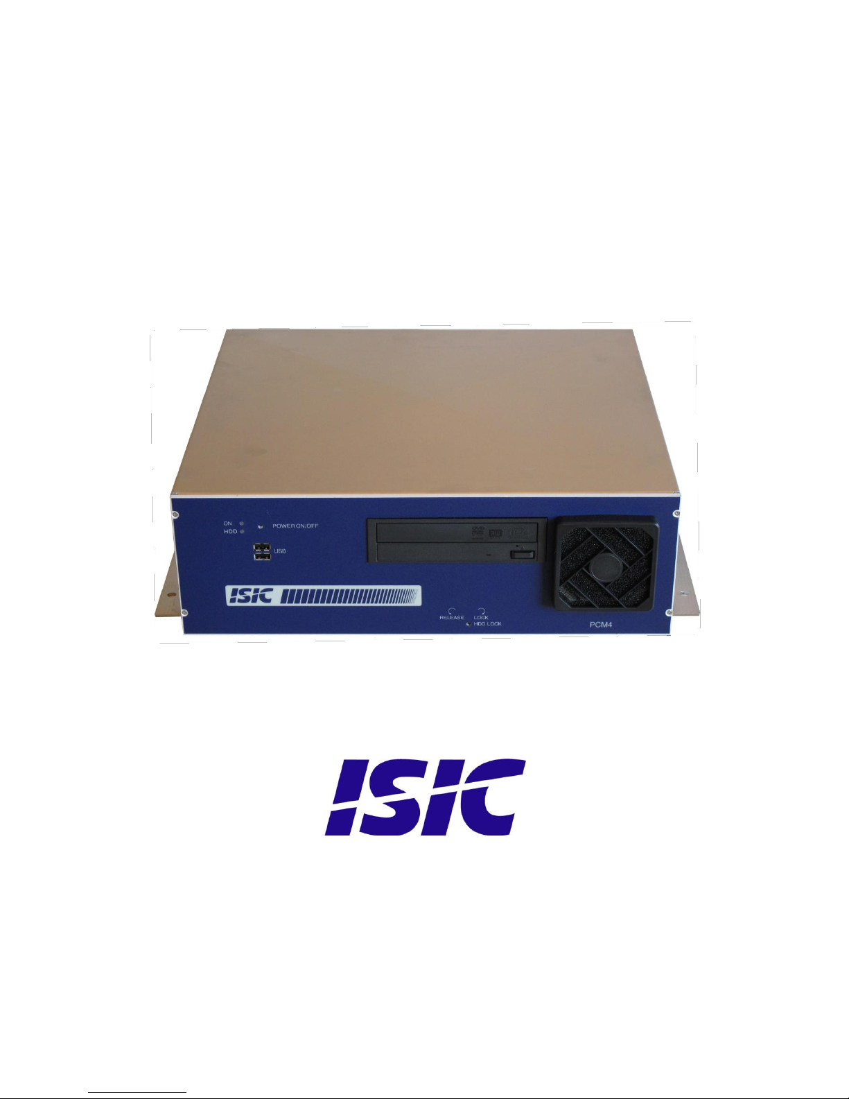
PCM4 manual
G43 version
Page 2

User Reference Manual, P/N:04868-000 Rev C Page 2
Disclaimer
ISIC A/S makes no representation or warranties with respect to the contents or use of this
manual, and specifically disclaims any express or implied warranties of merchantability or
fitness for any particular purpose. Further, ISIC A/S reserves the right to revise this
publication and to make changes to its content at any time, without obligation to notify any
person or entity of such revisions or changes.
FCC Warning
Computing devices and peripherals generate, use, and can radiate radio frequency energy, and
if not installed and used in accordance with the instructions advised by ISIC A/S, may cause
interference to radio communication.
The PCM4 series of PC‟s, manufactured by ISIC A/S, is designed to comply with the emerging
generic EEC standards, that cover applications in maritime environment.
Classification
The display is classified as Environmental condition “protected” acc. to EN60945 ed. 4
Approvals
Approval according to EN60945 ed. 4; Maritime navigation and radio communication
equipment and systems – General requirements.
ISIC A/S is complying with the WEEE directive within the European Union, stating that
electronic and electric products must be collected separately.
Products are marked according to the directive
Copyright 2009 ISIC A/S
ISIC P/N: 04868-000 Rev C
ISIC A/S
Edwin Rahrsvej 54
DK-8220 Brabrand
Denmark
Phone: +45 70 20 70 77
Fax: +45 70 20 79 76
Web: http://www.isic.dk
Page 3

User Reference Manual, P/N:04868-000 Rev C Page 3
ISIC PCM4 User Manual
Congratulations on your purchase of ISIC PCM4. This short form manual is designed to get you
started working with your new PCM4. It is not meant to cover all possible options or situations.
For a more detailed description of the PCM4 motherboard, please read the fully comprehensive
Main Board Manual obtainable on the CDROM.
Package contents:
1 PCM4
1 CDROM containing PCM4 Manual and Main Board Manual (optional)
1 Power cable (optional)
If any of these items are not present, please contact ISIC.
Page 4

User Reference Manual, P/N:04868-000 Rev C Page 4
Table of Contents
ISIC PCM4 USER MANUAL ......................................................................................................................................... 3
TABLE OF CONTENTS ................................................................................................................................................. 4
PCM4 OVERVIEW (DG43NB VERSION) ................................................................................................................... 5
MOTHERBOARD CONNECTION OVERVIEW (DG43NB VERSION) .................................................................. 6
PCM4 OVERVIEW (DP43TF VERSION)..................................................................................................................... 7
MOTHERBOARD CONNECTION OVERVIEW (DP43TF VERSION) ................................................................... 8
GETTING STARTED ...................................................................................................................................................... 9
BEFORE INSTALLING AT END CUSTOMER (HDD TRANSPORTATION LOCK) .......................................... 9
INSTALLING ADDITIONAL EXPANSION CARDS ............................................................................................... 10
MECHANICAL DIMENSIONS ................................................................................................................................... 11
MOUNTING POSITIONS ............................................................................................................................................. 12
PCM4 SYSTEM INDICATORS ................................................................................................................................... 13
TROUBLESHOOTING ................................................................................................................................................. 14
GENERAL NOTES ON USB ........................................................................................................................................ 14
SUPPORT........................................................................................................................................................................ 14
TECHNICAL SPECIFICATIONS (DG43NB VERSION) ......................................................................................... 15
TECHNICAL SPECIFICATIONS (DP43TF VERSION) .......................................................................................... 15
REVISION LOG ............................................................................................................................................................. 16
Page 5
User Reference Manual, P/N:04868-000 Rev C Page 5
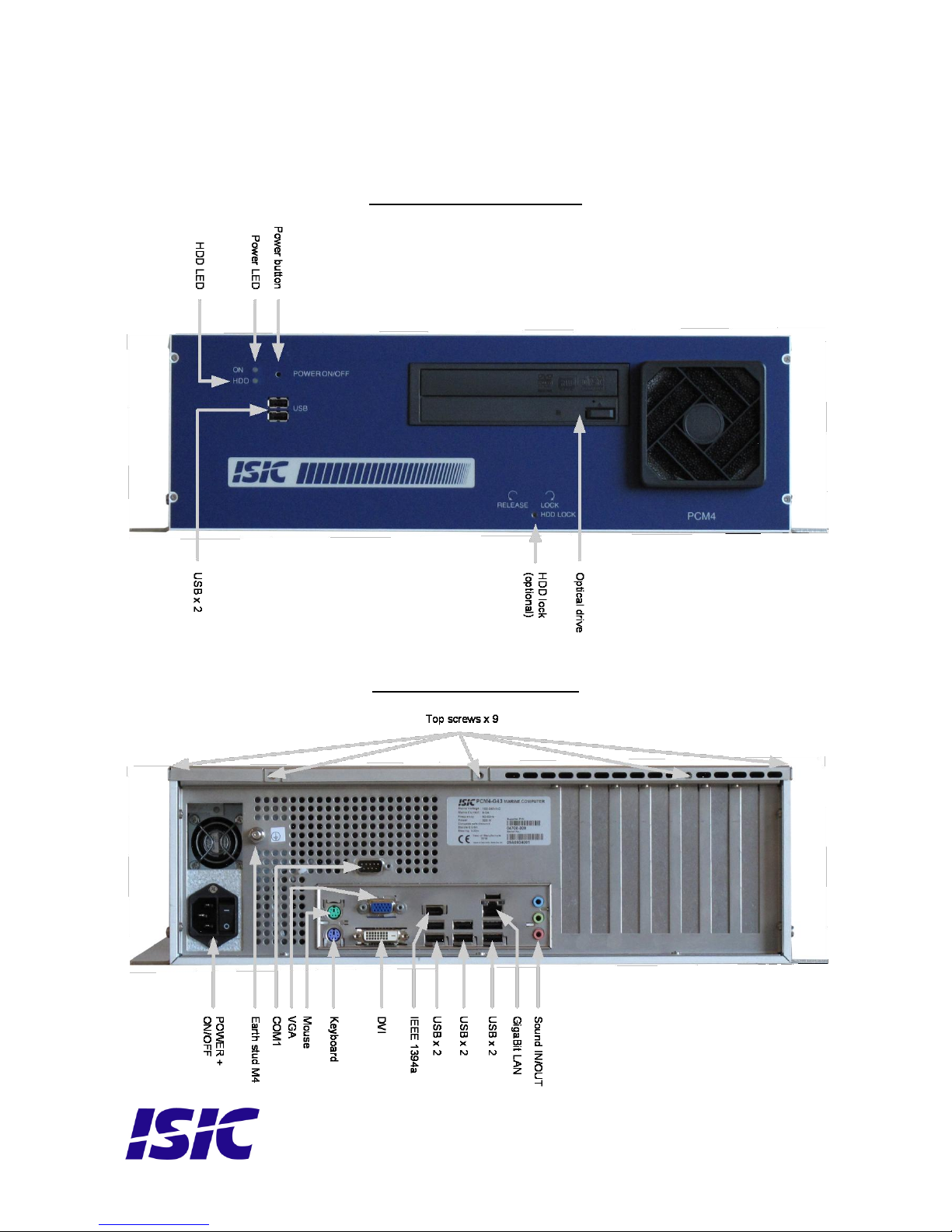
PCM4 overview (DG43NB version)
Front view PCM4-G43
Rear view PCM4-G43
Page 6
User Reference Manual, P/N:04868-000 Rev C Page 6
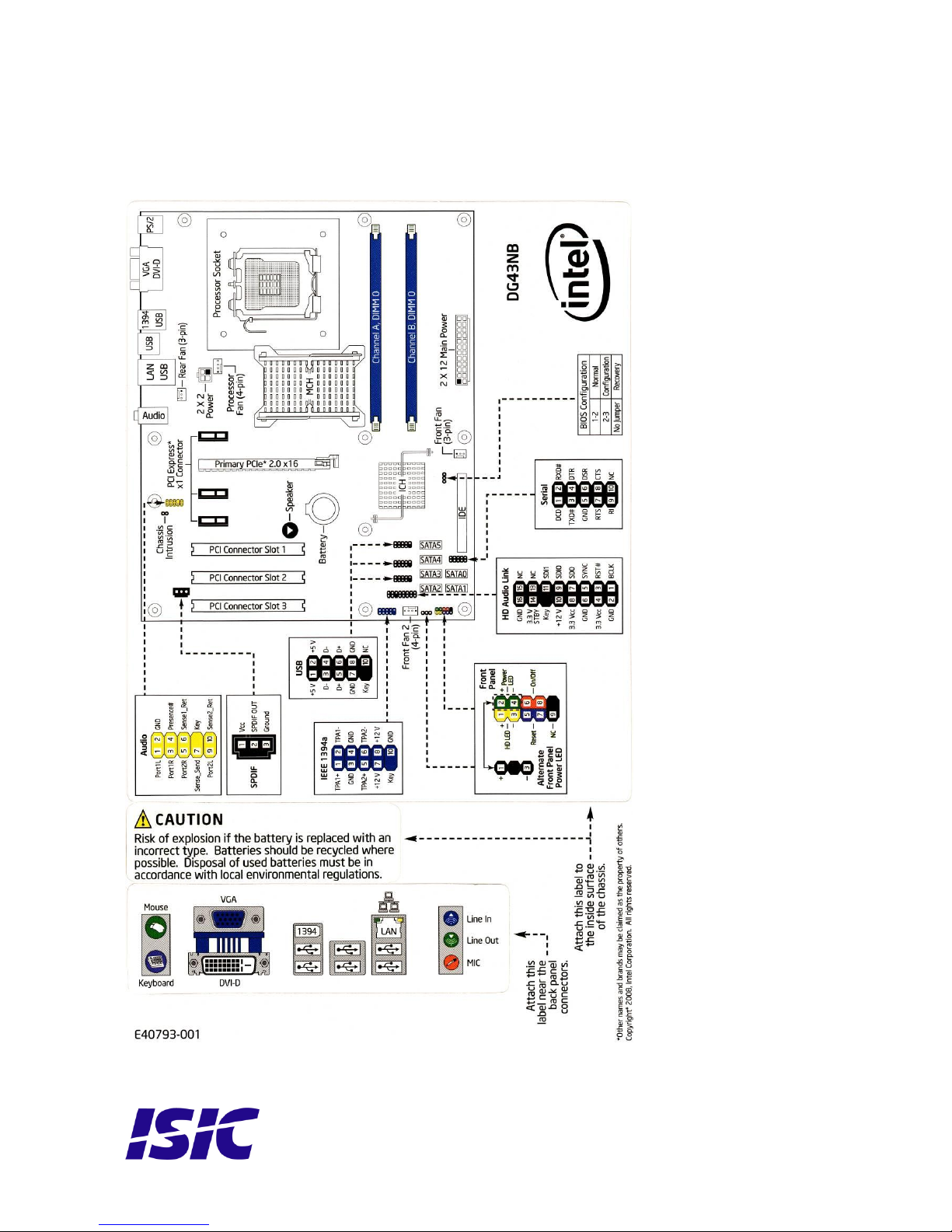
Motherboard connection overview (DG43NB version)
Below is an overview of motherboard connections and pin-out of the same.
Page 7
User Reference Manual, P/N:04868-000 Rev C Page 7
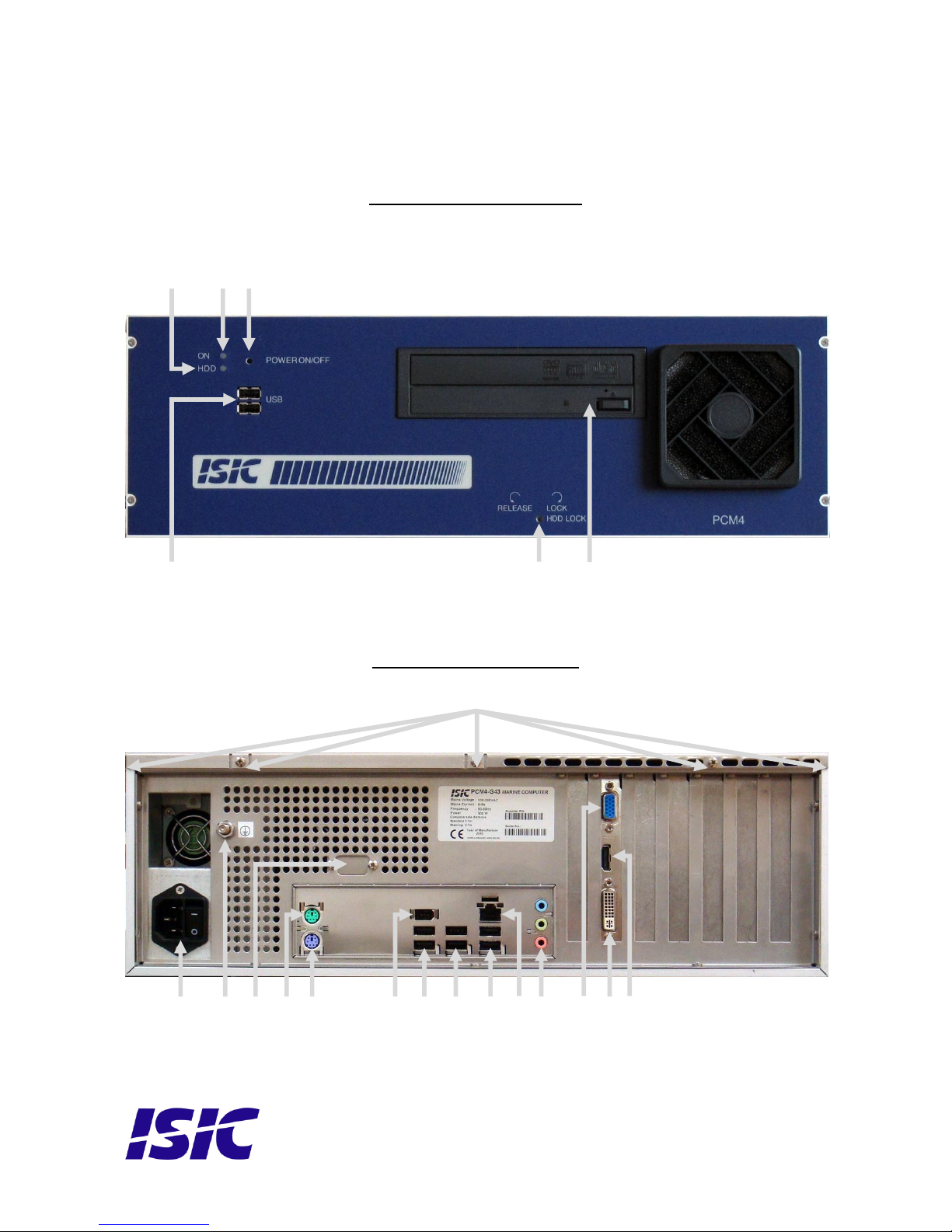
PCM4 overview (DP43TF version)
Front view PCM4-G43
Rear view PCM4-G43
USB x 2
HDD lock
(optional)
Optical drive
HDD LED
Power LED
Power button
POWER +
ON/OFF
Earth stud M4
COM1 (Optional)
Mouse
Keyboard
IEEE 1394a
USB x 2
USB x 2
USB x 2
GigaBit LAN
Sound IN/OUT
VGA
DVI
HDMI
Top screws x 9
Page 8
User Reference Manual, P/N:04868-000 Rev C Page 8
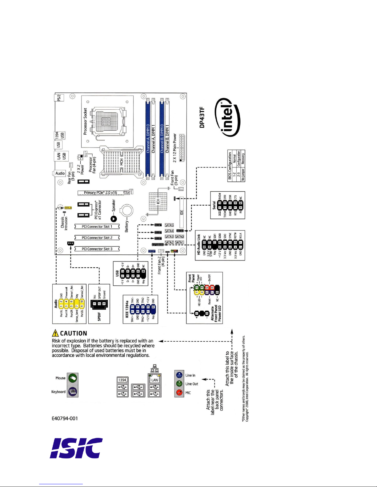
Motherboard connection overview (DP43TF version)
Below is an overview of motherboard connections and pin-out of the same.
Page 9
User Reference Manual, P/N:04868-000 Rev C Page 9
Getting started
Please refer to the PCM4 overview for location of connectors specified in this section.
Connect Keyboard/Mouse to the connectors specified in PCM4 overview or connect to the USB
connectors.
Connect the monitor to the RGB or DVI connector.
Connect all other needed connectors ending with the Power outlet.
Press the ON/OFF button to “I” position.
To power up the PCM4, you need to press the power button. Use a pencil or similar for that
purpose. If the temperature is very cold (below approx. 1.5°C) and the PCM4 has the special
ISIC HPC option (Heater Power Controller) the PCM4 will automatically begin warming the
components inside. That process will take some minutes. During that process, the power LED
will flash green to indicate the warming process. When the PCM4 has reached the sufficient
temperature, it will automatically start to boot.
Please refer to PCM4 system indicators on page 10 for an in-depth description.
The PCM4 will be in standby mode when you power down. To restart the PCM4 again, use a
pencil on the power button.
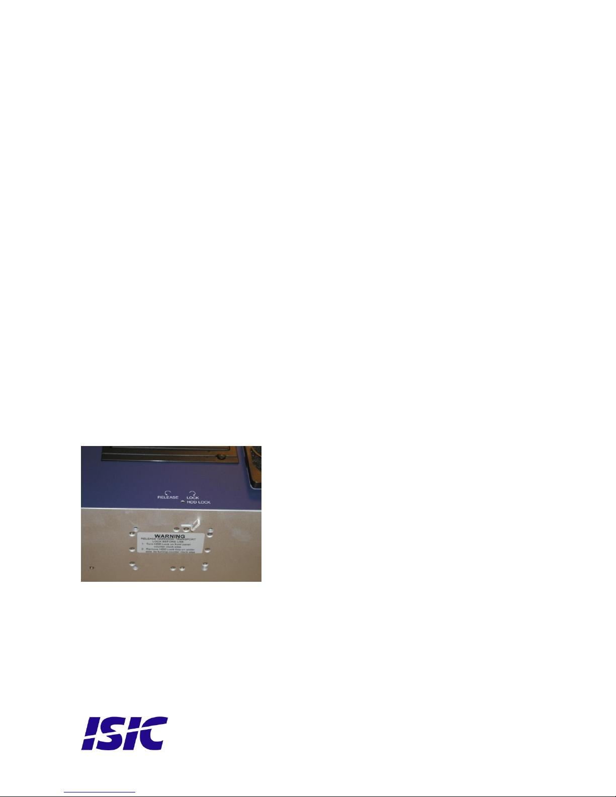
Before installing at end customer (HDD transportation lock)
First release the HDD transportation lock (optional) at the front of the PCM4. Rotate the screw
counter clock-wise until loose (about 8 full turns), then it is possible to remove the plastic key
in the bottom.
IMPORTANT: always lock the Hard Drive before shipping the PCM4.
Failing to lock the Hard Drive will void warranty!
The plastic key in the bottom of the cabinet is not needed to ship the PCM4
Page 10
User Reference Manual, P/N:04868-000 Rev C Page 10
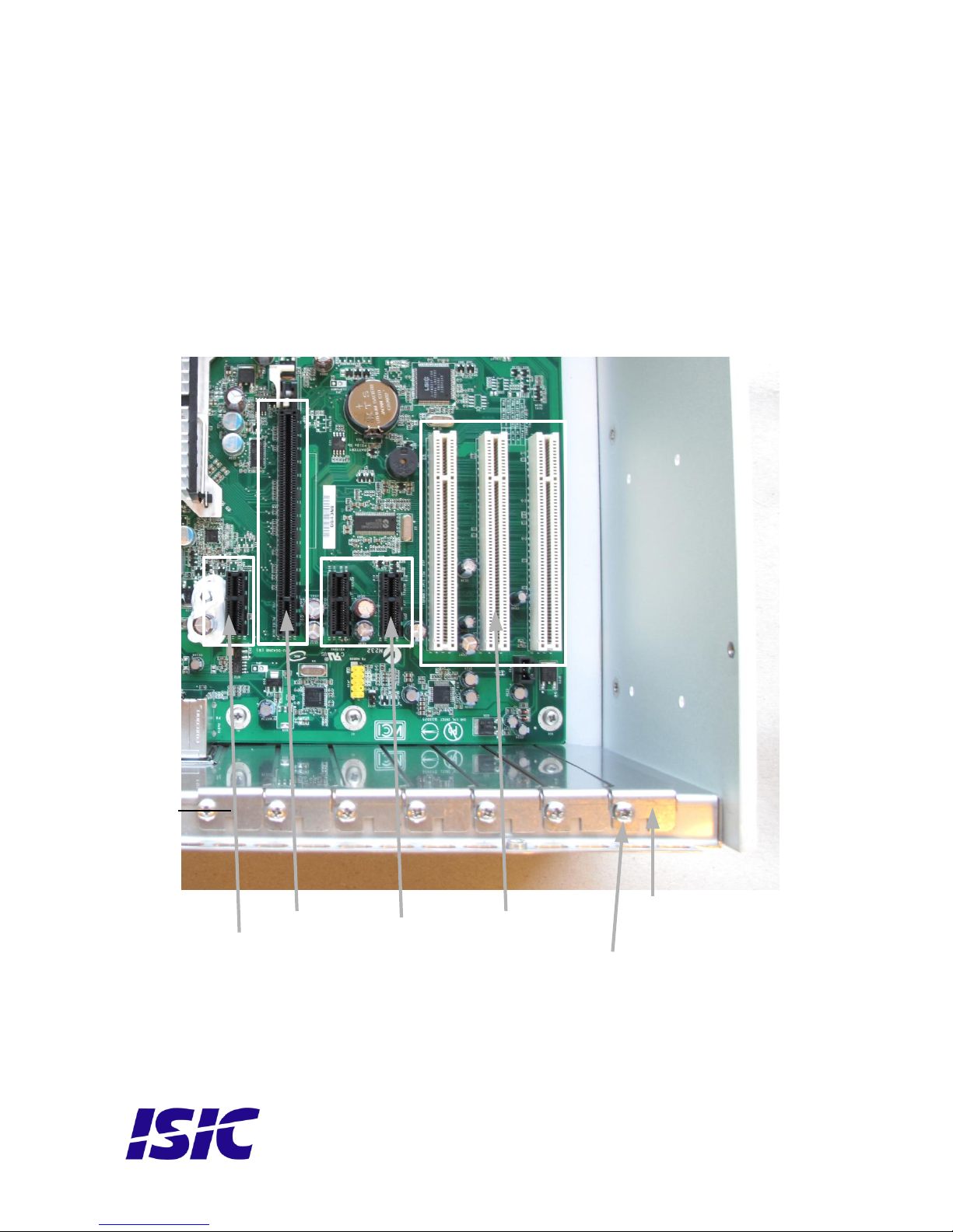
Installing additional expansion cards
Always disconnect the Power outlet before removing the top cover.
Remove the 9 overhead screws and top cover.
Remove the slot screw and remove the blind bracket. Install the add-on card in the slot and
then replace the slot screw. Replace the top cover and the 9 overhead screws.
PCM4-G43 motherboard
ATTENTION - This marine computer is covered by ISIC warranty, and any alterations
may render marine certificate and warranty invalid
PCIe x 1
PCIe x 16
2 times
PCIe x 1
3 times PCI
Blind
Bracket
Slot
screws
Page 11
User Reference Manual, P/N:04868-000 Rev C Page 11
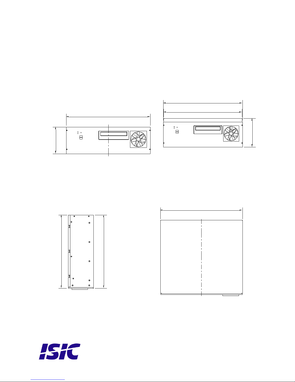
Mechanical dimensions
The cabinet is available in 2 heights, standard and extra high (for some oversize add-on cards)
Standard model Extra high model
152
414,5
418
132,5
418
381
Cover = 381,8
Cover = 420,5
Page 12
User Reference Manual, P/N:04868-000 Rev C Page 12
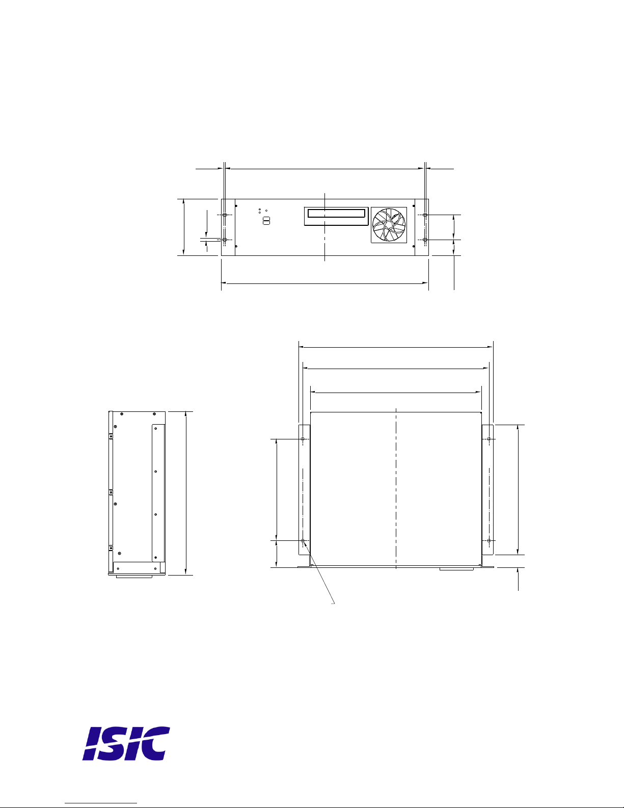
Cabinet with 19” brackets and rails.
Mounting positions
The PCM4 can be mounted in horizontal and vertical positions, but NOT upside down.
If needed, it is also possible to mount the PCM4 with the DVD drive facing downwards.
462,5 3,53,5
37,7 57,2
482,6 = 19''
6,8
132,5
32031
420,5
478
458
66 250
4 piece ø8
381
Page 13
User Reference Manual, P/N:04868-000 Rev C Page 13
PCM4 System Indicators
The PCM4 is equipped with two LED‟s, located on the case front.
Having a version without the ISIC HPC option (Heater Power Control), the upper LED is used to
simply indicate if the system is on or off, while the lower LED indicated Hard Disk activity.
In a PCM4 having the ISIC HPC option the display capability has been extended to provide an
indication of the current PCM4 system state. The lower LED still indicates Hard Disk activity;
the upper LED has been reconfigured as described in the following table:
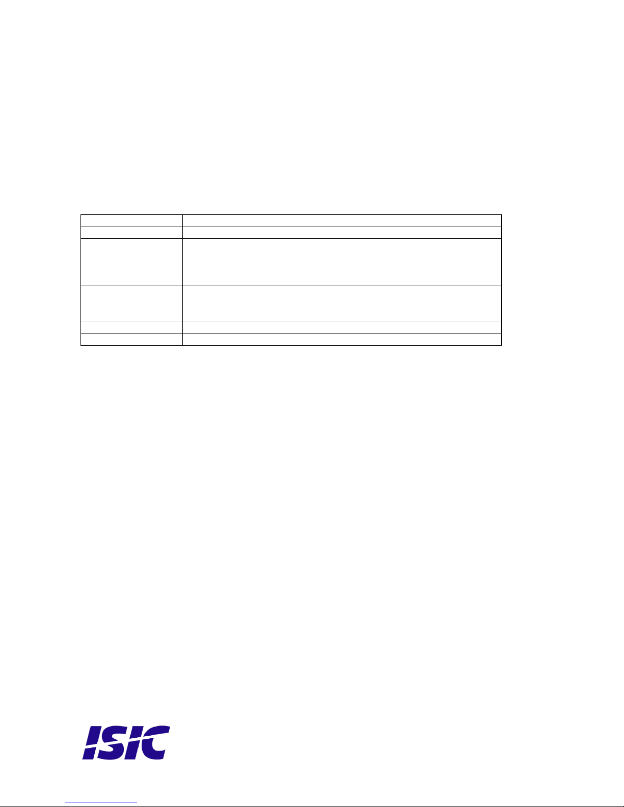
LED Indication
Description
Off
Power is removed from the system.
Red
Flashing
Boot sequence is delayed while the Hard Disk Drive is heated.
1.25 Hz : HDD Temperature is below -5°C
2.5 Hz : HDD Temperature is between -5°C and +5°C
5 Hz : HDD Temperature is above +5°C
Green
Flashing
The system is monitored for 10 seconds to ensure valid boot-up.
If the motherboard shuts down as a consequence of BIOS “Last
State” settings, it will be forced to reboot.
Green
System is on.
Red
System is in standby mode.
Page 14
User Reference Manual, P/N:04868-000 Rev C Page 14
Troubleshooting
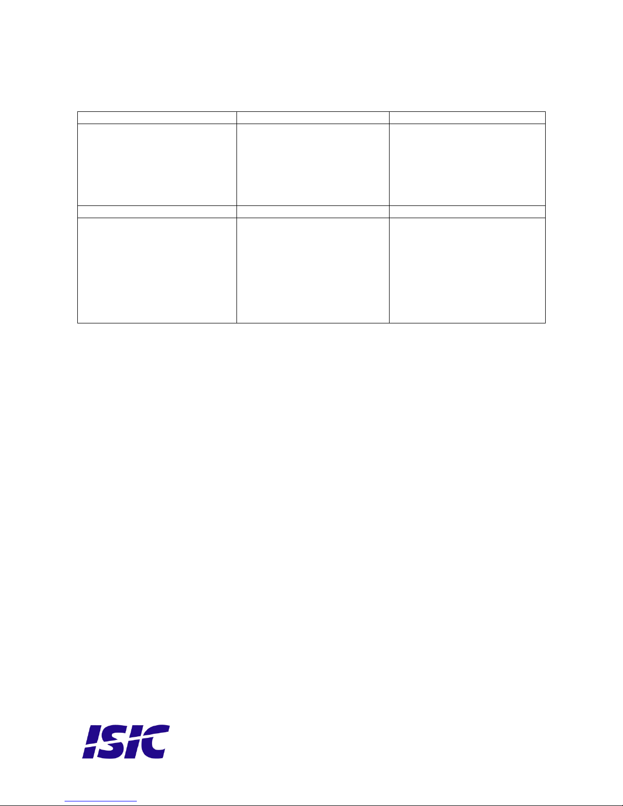
Problem
Cause
Solutions
The PCM4 won‟t start
- There is no power
connected
- Connect the power cord
- The ON/OFF button at the
rear side is in the „O‟ position
(ac version only)
- Push the ON/OFF button to
the „I‟ position
- The power button on the
front has not been pressed
- Use a pencil on the power
button
- USB power overload
- Read paragraph below
The PCM4 starts, but there is
no picture on the screen
- The display cable is not
connected, or have fallen out
- Connect the display cable
- The Power LED is flashing
green (HPC option only)
- The temperature is low and
the PCM4 is warming up. This
process will take about 5
minutes.
- Your brightness/contrast on
the monitor is either at max
or min level.
- Turn the brightness/contrast
to the correct levels.
General notes on USB
In the USB specification a max power consumption of 500mA on each USB port is specified.
If you experience start up problems, start by removing all USB devices, and then try to restart
the PCM4 again.
Faulty USB devices can also cause malfunction of your PCM4.
Support
In case you have problems with your PCM4, you have a number of possibilities to get support.
Visit our web site: www.isic.dk
Email us: [email protected]
Call during normal business hours (CET): +45 70 20 70 77
Page 15
User Reference Manual, P/N:04868-000 Rev C Page 15
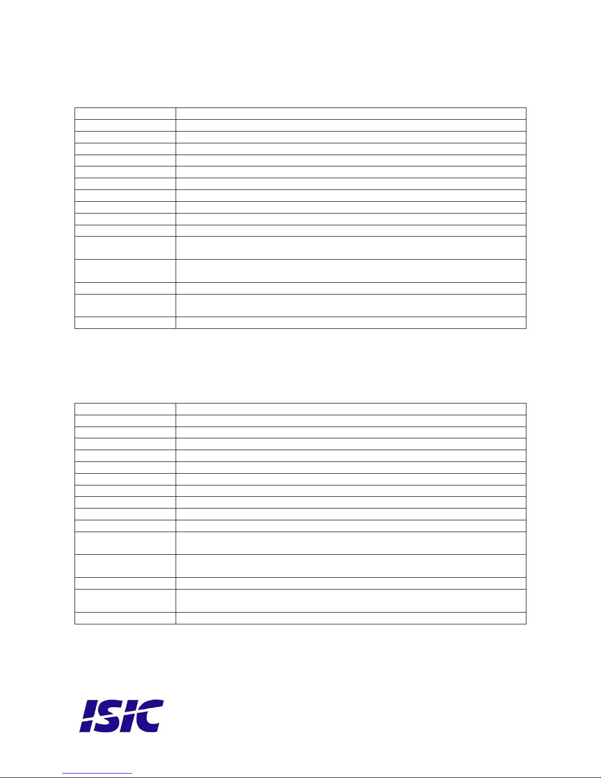
Technical specifications (DG43NB version)
CPU
Intel Core2Quad 2.66GHz or Intel Core2Duo 2.8GHz
Memory
256MB+ DDR2 SDRAM (4GB maximum)
Video
VGA x 1 and DVI x 1 (see details in your motherboard manual)
LAN
Gigabit LAN x 1 (see details in your motherboard manual)
Audio
5.1 + 2-channel (see details in your motherboard manual)
COM ports
RS232 x 1
Harddisk
40 GB+ SATA, 5400RPM, shock protected (several possibilities e.g. SSD)
CD-ROM
DVD ROM, CD-RW SATA drive
USB 2.0
2 x USB on front and 6 x USB on back
Power supply
90-265 VAC 300 Watt
Power consumption
100-150 watt typical (depending on processor type and add on cards)
Operation
temperature
-15 to 55°C
Storage
temperature
-25 to 70°C
Relative humidity
10 – 80 % (non-condensing)
Dimensions
(H/W/D)
132.5mm x 420.5mm x 381mm (without mounting brackets)
132.5mm x 478 mm x 381mm (with mounting brackets)
Weight
10.75 kg
Technical specifications (DP43TF version)
CPU
Intel Core2Quad 2.66GHz or Intel Core2Duo 2.8GHz
Memory
256MB+ DDR2 SDRAM (8GB maximum)
Video
VGA x 1, DVI x 1 and HDMI x 1
LAN
Gigabit LAN x 1 (see details in your motherboard manual)
Audio
5.1 + 2-channel (see details in your motherboard manual)
COM ports
RS232 x 1 (optional)
Harddisk
40 GB+ SATA, 5400RPM, shock protected (several possibilities e.g. SSD)
CD-ROM
DVD ROM, CD-RW SATA drive
USB 2.0
2 x USB on front and 6 x USB on back
Power supply
90-265 VAC 300 Watt
Power consumption
100-150 watt typical (depending on processor type and add on cards)
Operation
temperature
-15 to 55°C
Storage
temperature
-25 to 70°C
Relative humidity
10 – 80 % (non-condensing)
Dimensions
(H/W/D)
132.5mm x 420.5mm x 381mm (without mounting brackets)
132.5mm x 478 mm x 381mm (with mounting brackets)
Weight
10.75 kg
Page 16
User Reference Manual, P/N:04868-000 Rev C Page 16
Revision log
Revision
Date
Changes
A
Aug 2009
First release
B
Feb 2010
- Motherboard connection overview added
- Note added: “ATTENTION - This marine computer is covered by
ISIC warranty, and any alterations may render marine certificate
and warranty invalid”
C
Sep 2010
- DP43TF version added.
- Maximum RAM size added.
- Small typos fixed.
Page 17

 Loading...