

Page 1
User Reference Manual – DuraMON GLASS series
PN: 08186-000 Rev B Page 1
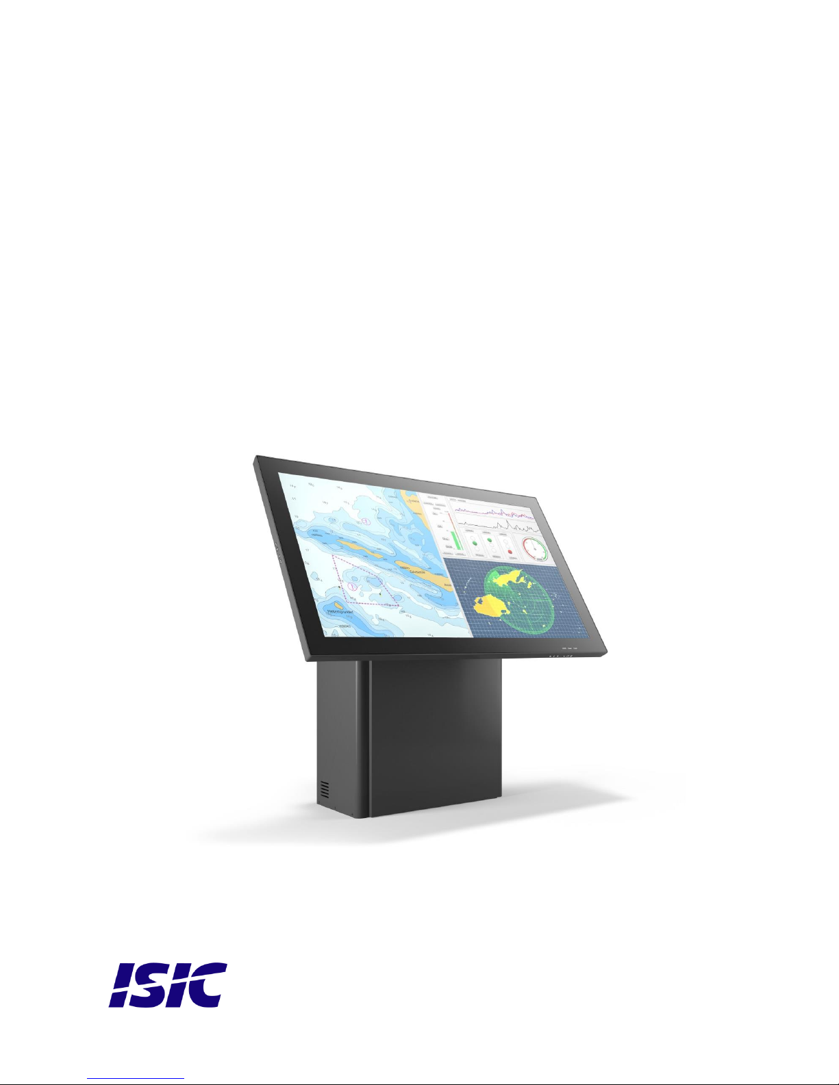
DuraMON 55 GLASS
User Reference Manual
Page 2

User Reference Manual – DuraMON GLASS series
PN: 08186-000 Rev B Page 2
Disclaimer
ISIC A/S makes no representation or warranties with respect to the contents or use of this manual,
and specifically disclaims any express or implied warranties of merchantability or fitness for any
particular purpose. Further, ISIC A/S reserves the right to revise this publication and to make
changes to its content at any time, without obligation to notify any person or entity of such revisions
or changes.
Image sticking: If the monitor is operated with static images (logo’s etc.) it will inevitably lead to
images sticking on the display. This is not a permanently situation and can be removed by
operating the monitor with a video that is created for this purpose.
FCC Warning
Computing devices and peripherals generate and radiate radio frequency energy, and if not
installed and used in accordance with the instructions advised by ISIC A/S, it may cause
interference to radio communication.
The DuraMON series, manufactured by ISIC A/S, is designed to comply with the emerging generic
EEC standards, that cover applications in maritime environment.
Classification
The monitor is classified as “protected from the weather” according to IEC 60945 ed.4 (former class
b).
Approvals
Approval according to IACS E10 ed. 6 and IEC 60945 ed. 4, Maritime navigation and radio
communication equipment and systems – General requirements.
ECDIS IEC 61174 ed. 4 compliant.
Radar IEC 62288 ed. 2 compliant.
Radar IEC 62388 ed. 2 compliant.
ISIC A/S is complying with the WEEE directive within the European Union, stating that electronic and
electric products must be collected separately.
Products are marked according to the directive.
Copyright 2017 ISIC A/S
ISIC A/S
Edwin Rahrs Vej 54
DK-8220 Brabrand
Denmark
Phone: +45 70 20 70 77
Fax: +45 70 20 79 76
Web: http://www.isic-systems.com
Page 3

User Reference Manual – DuraMON GLASS series
PN: 08186-000 Rev B Page 3
Table of Contents
1 FEATURES ............................................................................................................................................................... 4
2 GENERAL CONSIDERATIONS ON INSTALLATION AND OPERATION .................................................. 5
3 DURAMON 55 GLASS CONNECTIONS ............................................................................................................. 5
4 DURAMON 55 GLASS FRONT PANEL CONTROLS (ECDIS AND RADAR) ............................................... 6
4.1 DURAMON 55 GLASS FRONT: ................................................................ ........................................................... 6
5 SERIAL CONNECTION PIN-OUT ....................................................................................................................... 7
6 CONSOLE UP/DOWN/TILT CONNECTION PIN-OUT .................................................................................... 7
7 TECHNICAL SPECIFICATIONS DURAMON 55 GLASS ................................................................................ 8
8 MECHANICAL OUTLINE DURAMON 55 GLASS ............................................................................................ 9
9 MECHANICAL OUTLINE WALL MOUNT ..................................................................................................... 10
10 ECDIS MODE ..................................................................................................................................................... 11
11 DURA SERIAL COMMUNICATION PROTOCOL ...................................................................................... 11
12 COMPASS SAFE DISTANCE .......................................................................................................................... 11
13 POWER CONSUMPTION ................................................................................................................................ 11
14 INRUSH CURRENT .......................................................................................................................................... 12
1 POPUP MENU ........................................................................................................................................................ 13
2 ADVANCED OSD .................................................................................................................................................. 14
2.1 PICTURE............................................................................................................................................................. 14
2.2 PICTURE IN PICTURE .......................................................................................................................................... 16
2.3 SETUP ................................................................................................................................................................ 17
2.4 MONITOR INFO .................................................................................................................................................. 19
2.5 OSD SETTINGS .................................................................................................................................................. 19
3 TROUBLESHOOTING ......................................................................................................................................... 21
4 SERVICING THE UNIT ....................................................................................................................................... 21
5 TERMS, ACRONYMS AND ABBREVIATIONS ............................................................................................... 21
6 ISIC INFO / SUPPORT ......................................................................................................................................... 22
7 REVISION HISTORY ........................................................................................................................................... 23
8 APPENDIX A: PIXEL POLICY ........................................................................................................................... 24
Page 4

User Reference Manual – DuraMON GLASS series
PN: 08186-000 Rev B Page 4
1 Features
Congratulations on your purchase of a DuraMON 55 GLASS. This short form manual is designed to
get you started working with your new DuraMON 55 GLASS.
The DuraMON 55 GLASS monitor is made as rugged monitors especially designed for the
demanding operating conditions at sea.
The DuraMON 55 GLASS is tested for full compliance to marine-standards IACS E10 and IEC 60945.
The monitor comes with excellent brightness and contrast levels that, together with wide viewing
angles, ensure a good readability thus making it very eye-friendly. For the best picture quality,
always use a double shielded cable with ferrites, like the one supplied with the monitor.
Direct dimming control (1cd to100%) from UP/DOWN buttons (except ECDIS models).
Full settings control via menu or serial link.
IP65 protected front.
Multiple connections to cover the widest range of signal sources:
Display Port x 2
HDMI x 2
DVI-D
VGA
Optional Touch Screen available, but has to be ordered with the monitor.
Page 5
User Reference Manual – DuraMON GLASS series
PN: 08186-000 Rev B Page 5
2 General considerations on Installation and
Operation
The DuraMON GLASS is designed to work at conditions according to IEC 60945. However, keeping
the temperature and vibration level at a minimum will extend the life time of the product. ISIC
recommend operating this product at normal room temperature (20-25 °C), with the minimum of
direct sunlight, vibration and humidity.
Operation of the DuraMON 55 GLASS
To ensure that colors and luminance on the display are correct in ECDIS applications, do not use
the monitor until the warm-up period has completed.
The warm-up period is as follows:
Day mode
Dusk mode
Night mode
DuraMON 55 GLASS
30 min
30 min
30 min
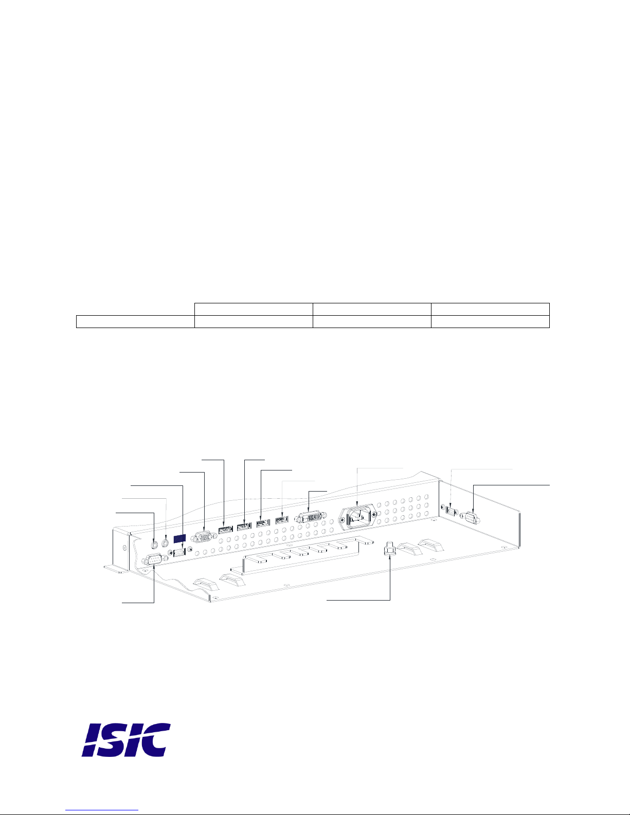
3 DuraMON 55 GLASS connections
Below is a view of optional connections to the monitor. The default inputs are: power, RS-232,
DP / HDMI, DVI and VGA.
Audio in
Audio out
Touch USB
VGA
DP1
HDMI2
DVI
Power AC
USB extern in
Lift and tilt control
M6 ground pin
DP2
HDMI1
RS232
Page 6
User Reference Manual – DuraMON GLASS series
PN: 08186-000 Rev B Page 6
4 DuraMON 55 GLASS front panel controls
(ECDIS and Radar)
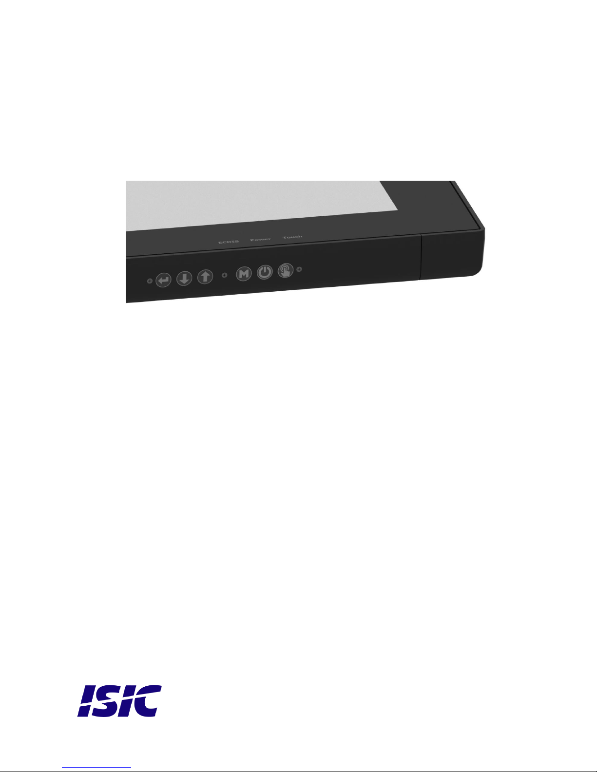
The front panel is illuminated and will follow the brightness level of the monitor backlight.
4.1 DuraMON 55 GLASS front:
STATUS:
This LED will illuminate green when the monitor is powered on and red when the monitor is powered
down. The LED will be red if no active signal is found.
ECDIS:
The LED will ONLY illuminate when the backlight level is at calibrated setting AND ONLY on an ECDIS
calibrated port.
Touch On/Off:
This button will activate or disable the touch sensor, there will be a text “Touch” that will light when
the touch is in-active. Be aware that it might take some seconds from enabling the touch to
computer detects it.
ON/OFF:
This key is used to turn the product on or off. Pressing it will turn the power on, while holding it
pressed down for 5 seconds will turn the power off. The status light will change from green to red to
indicate it’s powered down. It is important to notice that, when powered off, the product still
consumes some power from the mains. To cut off the power from the product it is necessary to
unplug its power cord from the mains.
Enter:
Use this to select the highlighted item in OSD menu.
UP/DOWN:
Used to adjust backlight or to navigate and adjust settings in menus. Pressing UP and DOWN
together will restore the backlight level to the last selected ECDIS mode by the serial link. (See
document 04924-001 for protocol details).
Menu:
To activate the OSD menu, press “Menu”.
See Popup Menu section for details.
Page 7
User Reference Manual – DuraMON GLASS series
PN: 08186-000 Rev B Page 7
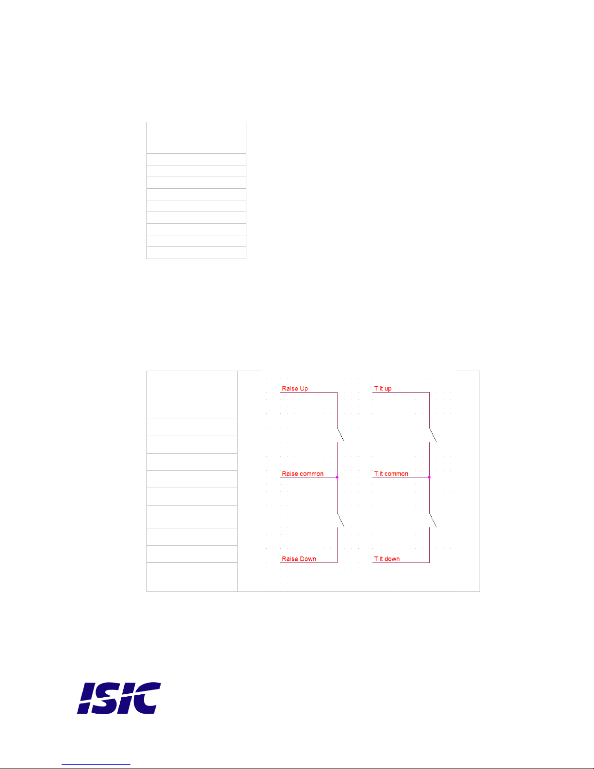
5 Serial connection pin-out
Pin
RS-232
SUB-D 9-pol female
1 2
RX 3 TX 4 5 GND 6 7 8 9
Mating connector 9 pin D-Sub male.
6 Floor stand Up/Down/Tilt connection pin-
out
Pin
Function
SUB-D 9-pol
male
1
Tilt Down
2
Raise Down
3
Raise Up
4
Tilt Up
5
Gnd
6
Raise
Common
7
Tilt Common
8
NC
9
NC
Mating connector 9 pin D-Sub female.
Page 8

User Reference Manual – DuraMON GLASS series
PN: 08186-000 Rev B Page 8
7 Technical specifications DuraMON 55
GLASS
DuraMON GLASS I/O
Video inputs:
1 x VGA: Up to 1920 x 1080 @ 60Hz
1 x DVI: Up to 1920 x 1080 @ 60Hz
2 x Display Port 1.2a: Up to 3840 x 2160 @ 60Hz
2 x HDMI 1.4: Up to 3840 x 2160 @ 30Hz
Recommended resolution is 3840 x 2160
Generally all VESA compatible video modes are supported.
External USB
Control inputs:
1x RS-232 – for remote control.
1x USB for touch sensor (optional).
1 x Raise up/down & tilt
DuraMON GLASS Power Supply Options
Standard:
90-260Vac 50-60Hz Input
DuraMON GLASS Environmental Conditions
Operating Temperature:
-15 to 55 °C
Storage Temperature:
-25 to 70 °C
Relative Humidity:
8 to 90 %
DuraMON GLASS Approvals
Marine:
ECDIS, Radar:
Type Approvals:
IEC 60945 Ed. 4, 2002-08 & IACS E10 Rev. 6 Oct. 2014
IEC 61174 ed. 4, IEC 62288 ed. 2, IEC 62388 ed. 2
For marine class approvals – see www.isic-systems.com
DuraMON55 specification
Resolution:
3840 x 2160
Active Area
1209.6mm x 680.4mm (55” diagonal)
Pixel Pitch:
0.315 mm x 0.315 mm
View angle:
89° (L/R/T/B) (typical)
Viewing distance:
1.10 m
Luminance:
450 cd/m2 (typical)
Contrast ratio:
4000:1 (typical)
Colors:
16.7 mill. (24-bit)
Response Time:
6.5 ms (GtG) (typical)
Protection:
IP65 front – IP20 rear
Weight:
75 kg
Dimensions (WxHxD):
1348,5 cm x 819,4 x 95 cm
Page 9
User Reference Manual – DuraMON GLASS series
PN: 08186-000 Rev B Page 9
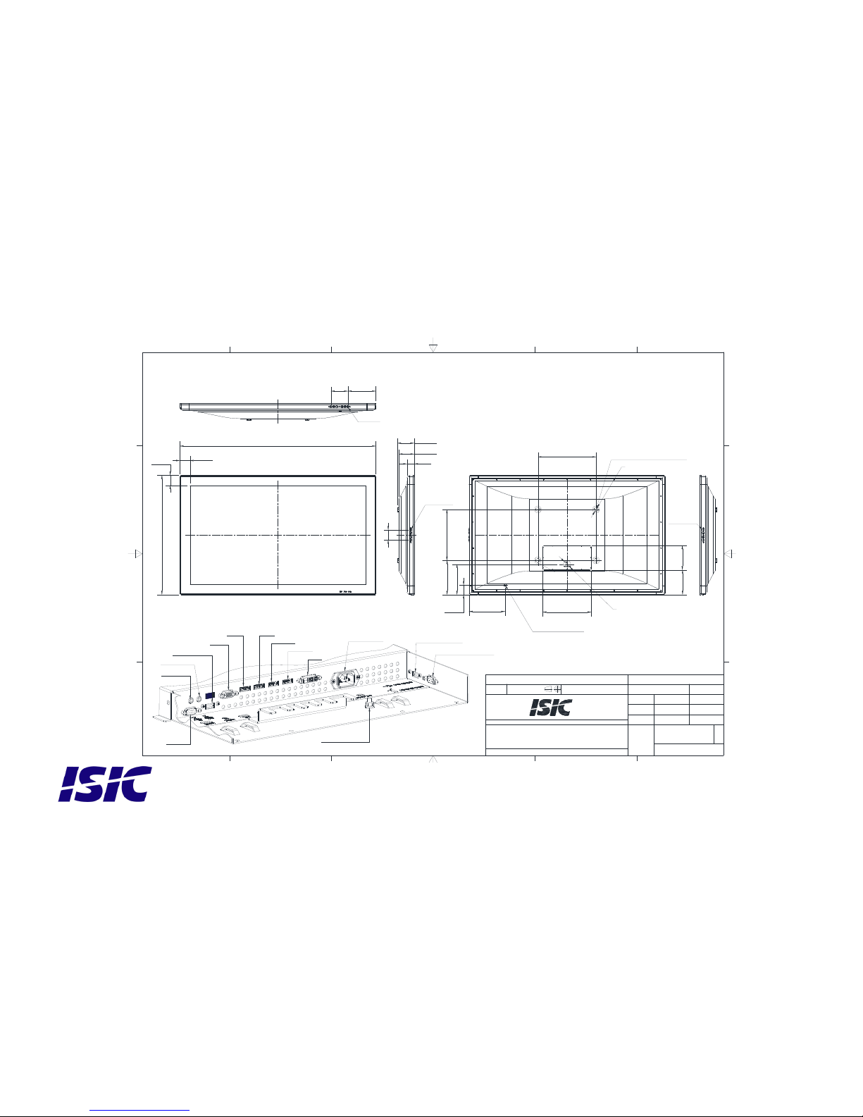
8 Mechanical outline DuraMON 55 GLASS
106,5
117
192,2
247,9
64,8
Lift and tilt buttons
Ø51,5 hole for connection cables
208,7
115,9
VESA 400
VESA 350
169,7
334
168
Ø29
50
70
4x M8x1.25 - 6H - 17
234,7
1348,4
819,4
69,4
69,2
1
1
2
2
3
3
4
4
5
5
6
6
A A
B B
C C
D D
Approved by
Projection method:
Drawing size:
Units: mm
Designed by
General tolerances: 0,2
Hole position: 0,1
Angle, straightness and flatness: DS/ISO 2768-H
Scale:
Drawing no.
Replaces:
Rev.
Subject:
ISIC A/S, Edwin Rahrs Vej 54, DK-8220 Brabrand. Tlf.: +45 70207077. Web: www.isic.dk
This docoment contains proprietary information and is not to be
used or reproduced without the written permission of ISIC A/S
Material:
Surface:
Sheet: 1 of 1
ksc 25-09-2017
A3
Mechanical outline DuraMON WS Glass 55''
AC
NHL
25-09-2017
1:5
08207-000
B
ECO
2319
USB extern out
Audio in
Audio out
Touch USB
VGA
DP1
HDMI2
DVI
Power AC
USB extern in
Lift and tilt control
M6 ground pin
DP2
HDMI1
Lift and tilt buttons
Menu buttons
RS232
Monitor 65kg
Page 10
User Reference Manual – DuraMON GLASS series
PN: 08186-000 Rev B Page 10
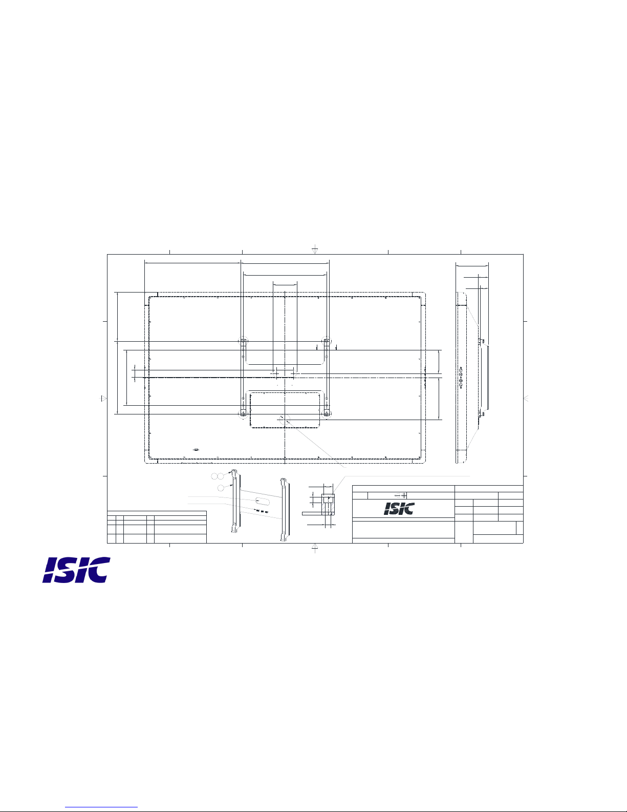
9 Mechanical outline Wall Mount
Countersunk Mounting holes for 4x bolt M10 ISO 4762
425
1
3x Cable anchor
Cable access
201
Ø51,5 hole for connection cables
350
40
Ø18
10,5
Ø11
Mounting holes 265
Mounting holes 400
49,9
156,4
(461,7)
(234,7)
Cable access 115
Cable access 35
112,5
A-A ( 1 : 2 )
1
1
2
2
3
3
4
4
5
5
6
6
A A
B B
C C
D D
Approved by
Projection method:
Drawing size:
Units: mm
Designed by
General tolerances: 0,2
Hole position: 0,1
Angle, straightness and flatness: DS/ISO 2768-H
Scale:
Drawing no.
Replaces:
Rev.
Subject:
ISIC A/S, Edwin Rahrs Vej 54, DK-8220 Brabrand. Tlf.: +45 70207077. Web: www.isic.dk
This docoment contains proprietary information and is not to be
used or reproduced without the written permission of ISIC A/S
Material:
Surface:
Sheet: 1 of 1
ksc 25-09-2017
A3
DuraMON Glass 55 Wall Mount outline
NHL
25-09-2017
1:5
08361-000
B
ECO
2319
A A
Parts List
DESCRIPTION
REVPART NUMBER
QTY
ITEM
DuraMON Glass 55 Wall Mount
A08360-00011
SCREW 6KT M8x30 DIN 933 A4
(ISO 4017)
00233-00142
SKIVE PLAN Ø8,4X16X1,6 RF
DIN125A A2
00238-00544
24
Page 11

User Reference Manual – DuraMON GLASS series
PN: 08186-000 Rev B Page 11
10 ECDIS mode
Be aware that use of the backlight, brightness or contrast controls in ECDIS mode may inhibit
visibility of information particularly at night!
To setup ECDIS on the system a color map must be downloaded from the monitor to the ECDIS
application. Please see the Dura Serial Communication protocol for details.
11 Dura Serial Communication protocol
See document 04924-001 for protocol details.
The type of the product can be queried by sending the ‘TYP’ command, ref. the Serial Protocol
Document
Monitor
Response from monitor
DuraMON 55 GLASS
DuraMON 55 GLASS
12 Compass safe distance
Test object / condition
Minimum Compass safe
distance [cm]
(5.4°/H deviation or a
horizontal magnetic flux of
0.094µT)
Minimum Compass safe
distance [cm]
(18°/H deviation or a horizontal
magnetic flux of 0.313µT)
DuraMON 55 GLASS
560 cm
360 cm
13 Power Consumption
Test object / condition
Ptyp [W]
Pmax [W]
DuraMON 55 GLASS
125
200
Page 12

User Reference Manual – DuraMON GLASS series
PN: 08186-000 Rev B Page 12
14 Inrush current
Test object /
condition
100
[VAC]
240
[VAC]
DuraMON 55 GLASS
45
108
Page 13
User Reference Manual – DuraMON GLASS series
PN: 08186-000 Rev B Page 13
Check OSD menu
1 Popup Menu
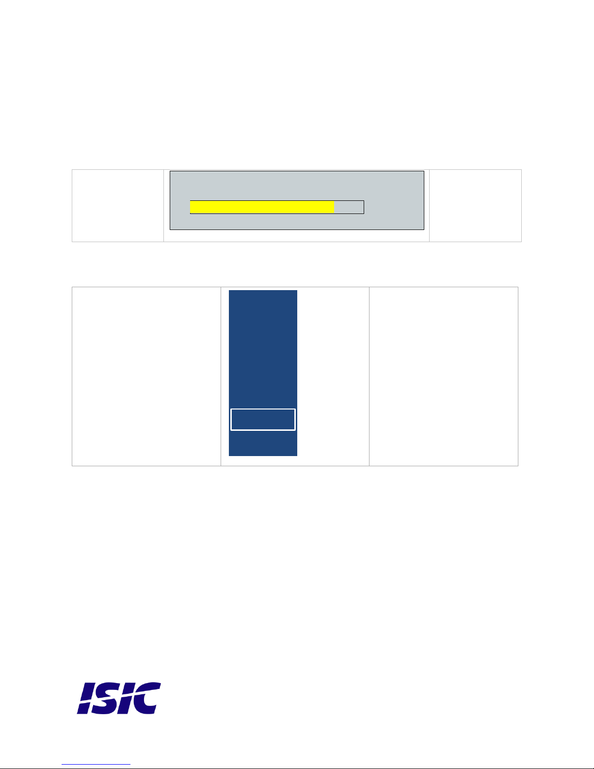
Without entering the OSD menu it is possible to adjust brightness by pressing “up” or “down” key.
Press “up” or
“down”
It is now possible to
adjust the backlight
level by pressing
either up- or down
key.
Without entering the OSD menu it is possible to select which input is active by pressing “Enter”.
Press “Enter” to activate this
menu.
Input
VGA
DVI
HDMI1
HDMI2
DP1
DP2
Use “up” or “down” key and
then press enter to select
another input channel.
Backlight
80
Page 14
User Reference Manual – DuraMON GLASS series
PN: 08186-000 Rev B Page 14
2 Advanced OSD
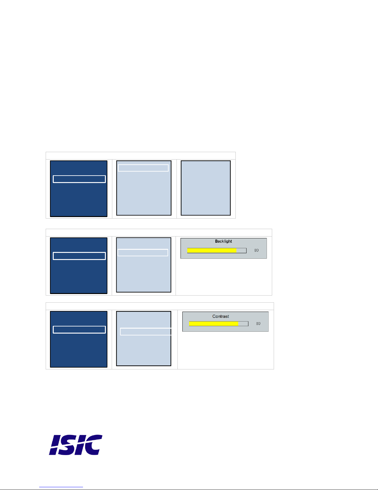
With the Advanced OSD (On Screen Display) you can modify the settings and control the special
features of the DuraMON as described on the next pages.
To enter the Advanced OSD, press “MENU” button.
To navigate the Advanced OSD use the “UP” and “DOWN” buttons and press “ENTER” to select a
specific setting. To get back to the previous menu point, press the “MENU” button.
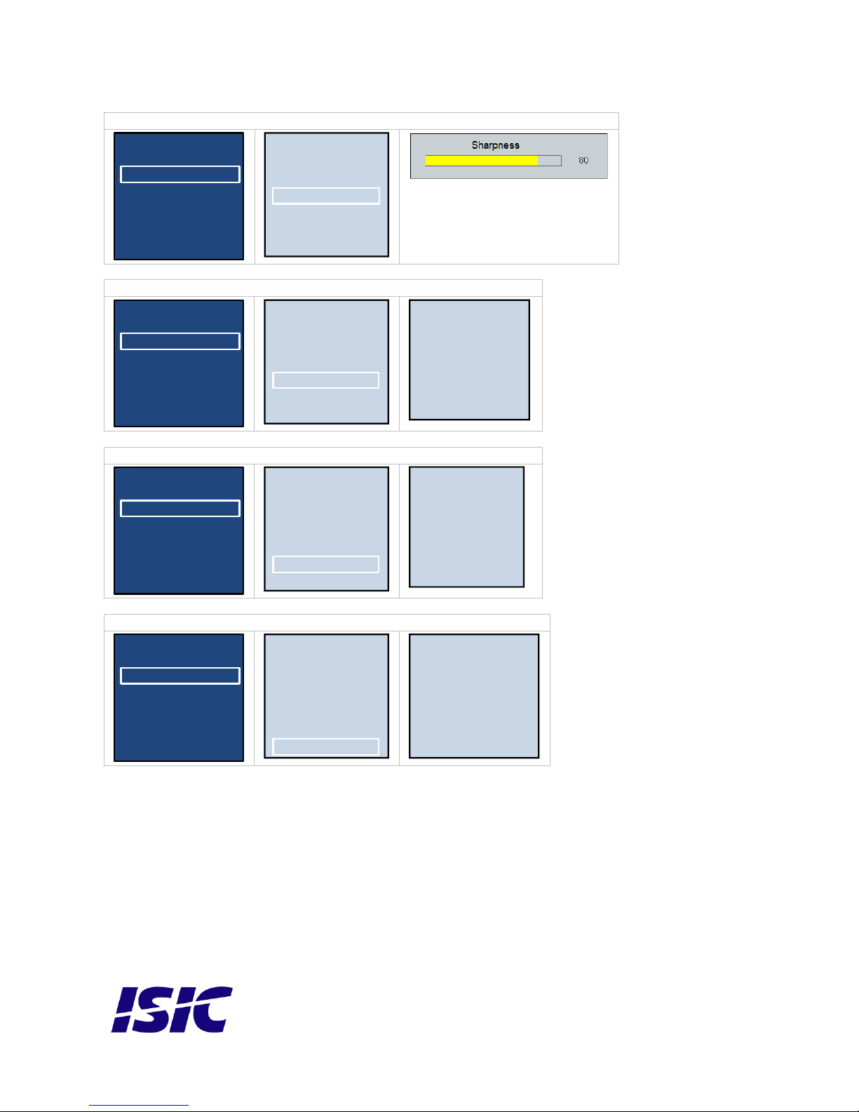
2.1 Picture
Picture – Picture format
Main Menu
Picture
PIP PBP
Audio
Setup
Monitor Info
OSD Settings
Picture Format
Brightness
Contrast
Sharpness
Gamma
Color Temp
User
Wide Screen
4:3
1:1
Picture – Picture Brightness
Main Menu
Picture
PIP PBP
Audio
Setup
Monitor Info
OSD Settings
Picture Format
Brightness
Contrast
Sharpness
Gamma
Color Temp
User
Picture – Picture Contrast
Main Menu
Picture
PIP PBP
Audio
Setup
Monitor Info
OSD Settings
Picture Format
Brightness
Contrast
Sharpness
Gamma
Color Temp
User
Page 15
User Reference Manual – DuraMON GLASS series
PN: 08186-000 Rev B Page 15
Picture – Picture Sharpness
Main Menu
Picture
PIP PBP
Audio
Setup
Monitor Info
OSD Settings
Picture Format
Brightness
Contrast
Sharpness
Gamma
Color Temp
User
Picture – Picture Gamma
Main Menu
Picture
PIP PBP
Audio
Setup
Monitor Info
OSD Settings
Picture Format
Brightness
Contrast
Sharpness
Gamma
Color Temp
User
1.8
2.0
2.2
2.4
2.6
Picture – Picture Color Temp
Main Menu
Picture
PIP PBP
Audio
Setup
Monitor Info
OSD Settings
Picture Format
Brightness
Contrast
Sharpness
Gamma
Color Temp
User
Warm
Normal
Cool
User
Picture – Picture User
Main Menu
Picture
PIP PBP
Audio
Setup
Monitor Info
OSD Settings
Picture Format
Brightness
Contrast
Sharpness
Gamma
Color Temp
User
Green 50
Blue 50
Red 50
Page 16
User Reference Manual – DuraMON GLASS series
PN: 08186-000 Rev B Page 16
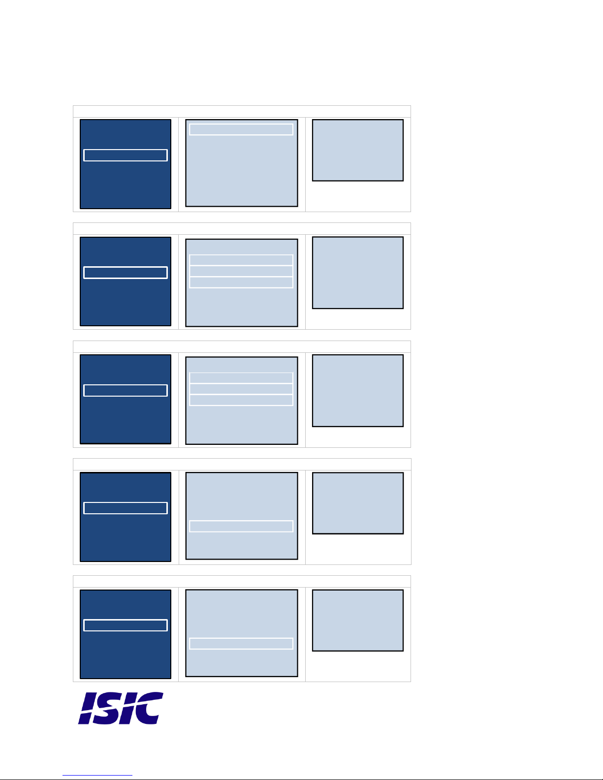
2.2 Picture in Picture
PIP PBP PIP/PBP Mode
Main Menu
Picture
PIP PBP
Audio
Setup
Monitor Info
OSD Settings
Win1 Input Sub DVI
Win2 Input Sub DVI
Win3 Input Sub DVI
PIP Size Small
PIP Position Top-Right
PIP/PBP Mode PBP 4Win
Swap
Off
PIP
PBP 2Win
PBP 3Win
PBP 4Win
PIP PBP Win1 Input Sub
Main Menu
Picture
PIP PBP
Audio
Setup
Monitor Info
OSD Settings
Win1 Input Sub DVI
Win2 Input Sub DVI
Win3 Input Sub DVI
PIP Size Small
PIP Position Top-Right
PIP/PBP Mode PBP 4Win
Swap
VGA
DVI
HD1
HD2
DP2
DP1
PIP PBP Win1 Input Sub
Main Menu
Picture
PIP PBP
Audio
Setup
Monitor Info
OSD Settings
Win1 Input Sub DVI
Win2 Input Sub DVI
Win3 Input Sub DVI
PIP Size Small
PIP Position Top-Right
PIP/PBP Mode PBP 4Win
Swap
VGA
DVI
HD1
HD2
DP2
DP1
PIP PBP PIP Size
Main Menu
Picture
PIP PBP
Audio
Setup
Monitor Info
OSD Settings
Win1 Input Sub DVI
Win2 Input Sub DVI
Win3 Input Sub DVI
PIP Size Small
PIP Position Top-Right
PIP/PBP Mode PBP 4Win
Swap
Small
Middle
Large
PIP PBP PIP Size
Main Menu
Picture
PIP PBP
Audio
Setup
Monitor Info
OSD Settings
Win1 Input Sub DVI
Win2 Input Sub DVI
Win3 Input Sub DVI
PIP Size Small
PIP Position Top-Right
PIP/PBP Mode PBP 4Win
Swap
Small
Middle
Large
Page 17
User Reference Manual – DuraMON GLASS series
PN: 08186-000 Rev B Page 17
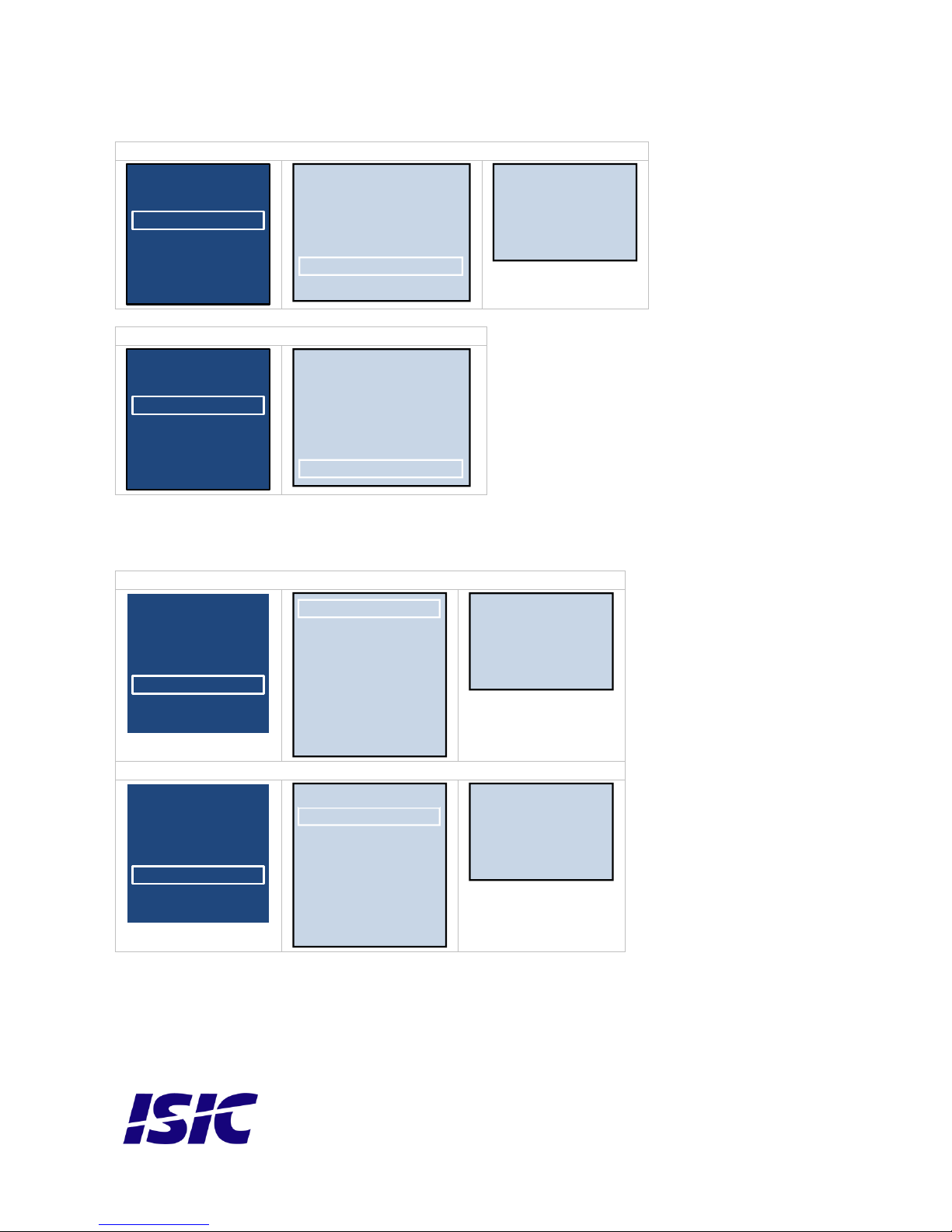
PIP PBP PIP Position
Main Menu
Picture
PIP PBP
Audio
Setup
Monitor Info
OSD Settings
Win1 Input Sub DVI
Win2 Input Sub DVI
Win3 Input Sub DVI
PIP Size Small
PIP Position Top-Right
PIP/PBP Mode PBP 4Win
Swap
Top-Right
Top-Left
Bottom-Right
Bottom-Left
PIP PBP Swap
Main Menu
Picture
PIP PBP
Audio
Setup
Monitor Info
OSD Settings
Win1 Input Sub DVI
Win2 Input Sub DVI
Win3 Input Sub DVI
PIP Size Small
PIP Position Top-Right
PIP/PBP Mode PBP 4Win
Swap
2.3 Setup
Setup - DisplayPort
Main Menu
Picture
PIP PBP
Audio
Setup
Monitor Info
OSD Settings
Input Scan Yes
Reset No
Auto
H. Position
V. Position
DisplayPort 1.2
Phase
Clock
1.1
1.2
Setup – Input Scan
Main Menu
Picture
PIP PBP
Audio
Setup
Monitor Info
OSD Settings
Input Scan Yes
Reset No
Auto
H. Position
V. Position
DisplayPort 1.2
Phase
Clock
Yes
No
Page 18
User Reference Manual – DuraMON GLASS series
PN: 08186-000 Rev B Page 18
Setup – Reset
Main Menu
Picture
PIP PBP
Audio
Setup
Monitor Info
OSD Settings
Input Scan Yes
Reset No
Auto
H. Position
V. Position
DisplayPort 1.2
Phase
Clock
Yes
No
Setup – Auto
Main Menu
Picture
PIP PBP
Audio
Setup
Monitor Info
OSD Settings
Input Scan Yes
Reset No
Auto
H. Position
V. Position
DisplayPort 1.2
Phase
Clock
Only available for VGA
Setup – H. Position
Main Menu
Picture
PIP PBP
Audio
Setup
Monitor Info
OSD Settings
Input Scan Yes
Reset No
Auto
H. Position
V. Position
DisplayPort 1.2
Phase
Clock
Only available for VGA
Setup – V. Position t
Main Menu
Picture
PIP PBP
Audio
Setup
Monitor Info
OSD Settings
Input Scan Yes
Reset No
Auto
H. Position
V. Position
DisplayPort 1.2
Phase
Clock
Only available for VGA
Page 19
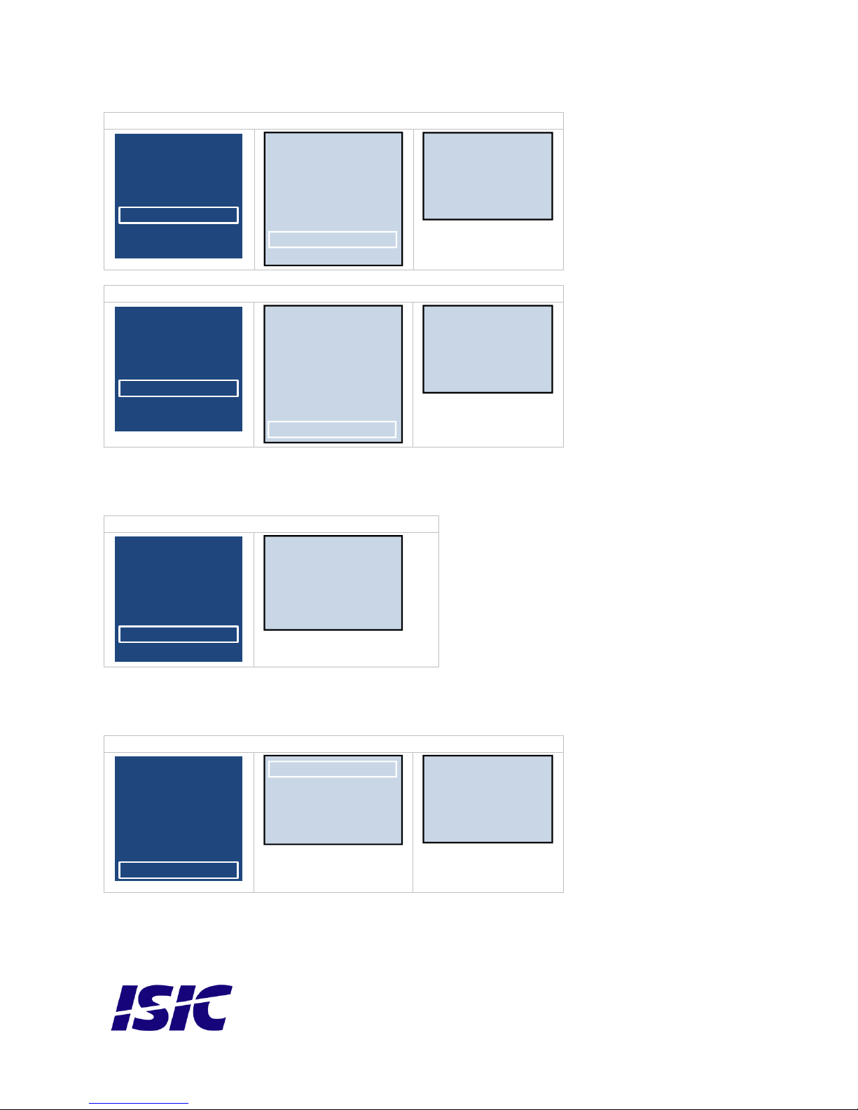
User Reference Manual – DuraMON GLASS series
PN: 08186-000 Rev B Page 19
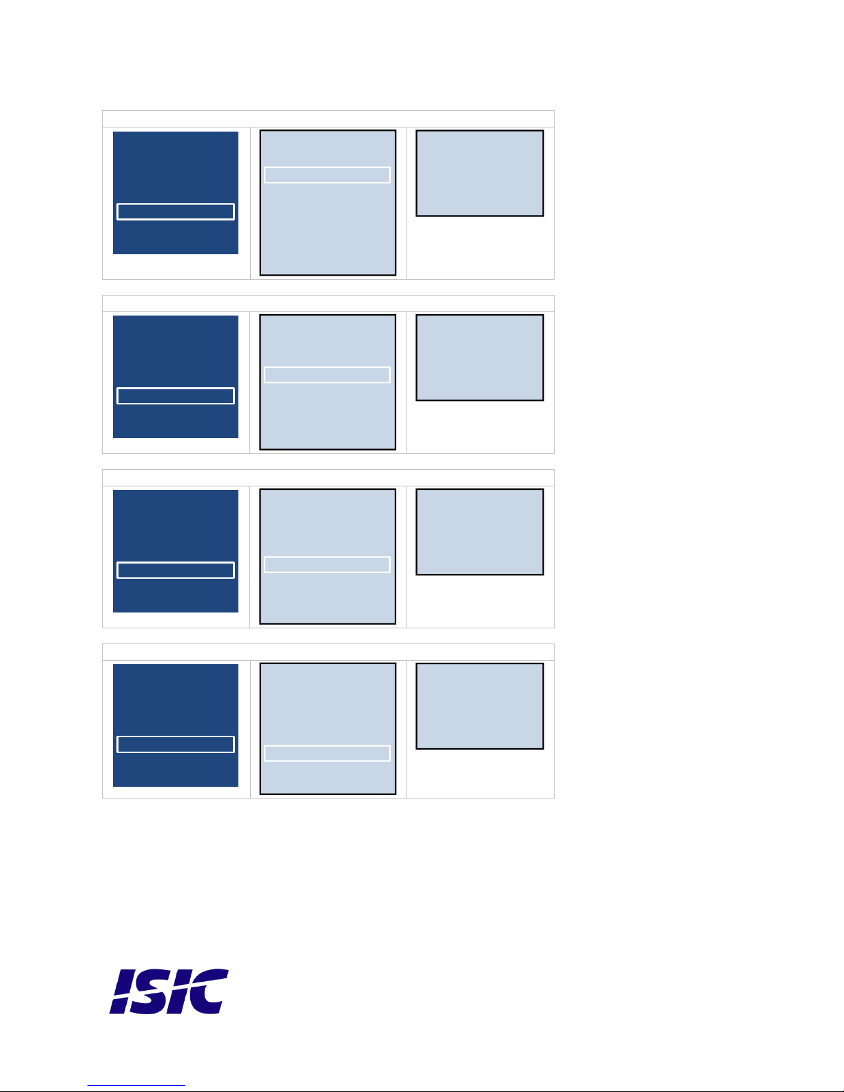
Setup – Phase
Main Menu
Picture
PIP PBP
Audio
Setup
Monitor Info
OSD Settings
Input Scan Yes
Reset No
Auto
H. Position
V. Position
DisplayPort 1.2
Phase
Clock
Only available for VGA
Setup – Clock
Main Menu
Picture
PIP PBP
Audio
Setup
Monitor Info
OSD Settings
Input Scan Yes
Reset No
Auto
H. Position
V. Position
DisplayPort 1.2
Phase
Clock
Only available for VGA
2.4 Monitor Info
Monitor Info
Main Menu
Picture
PIP PBP
Audio
Setup
Monitor Info
OSD Settings
FW Part no: xx
Compas Safe Distance xx
Standard: xx
Steering: xx
DuraMon xx
2.5 OSD Settings
Setup – Horizontal
Main Menu
Picture
PIP PBP
Audio
Setup
Monitor Info
OSD Settings
Vertical 50
Transparency Off
OSD Time Out 20s
Upgrade Sw
Horizontal 50
Value from 0 to 100
Page 20
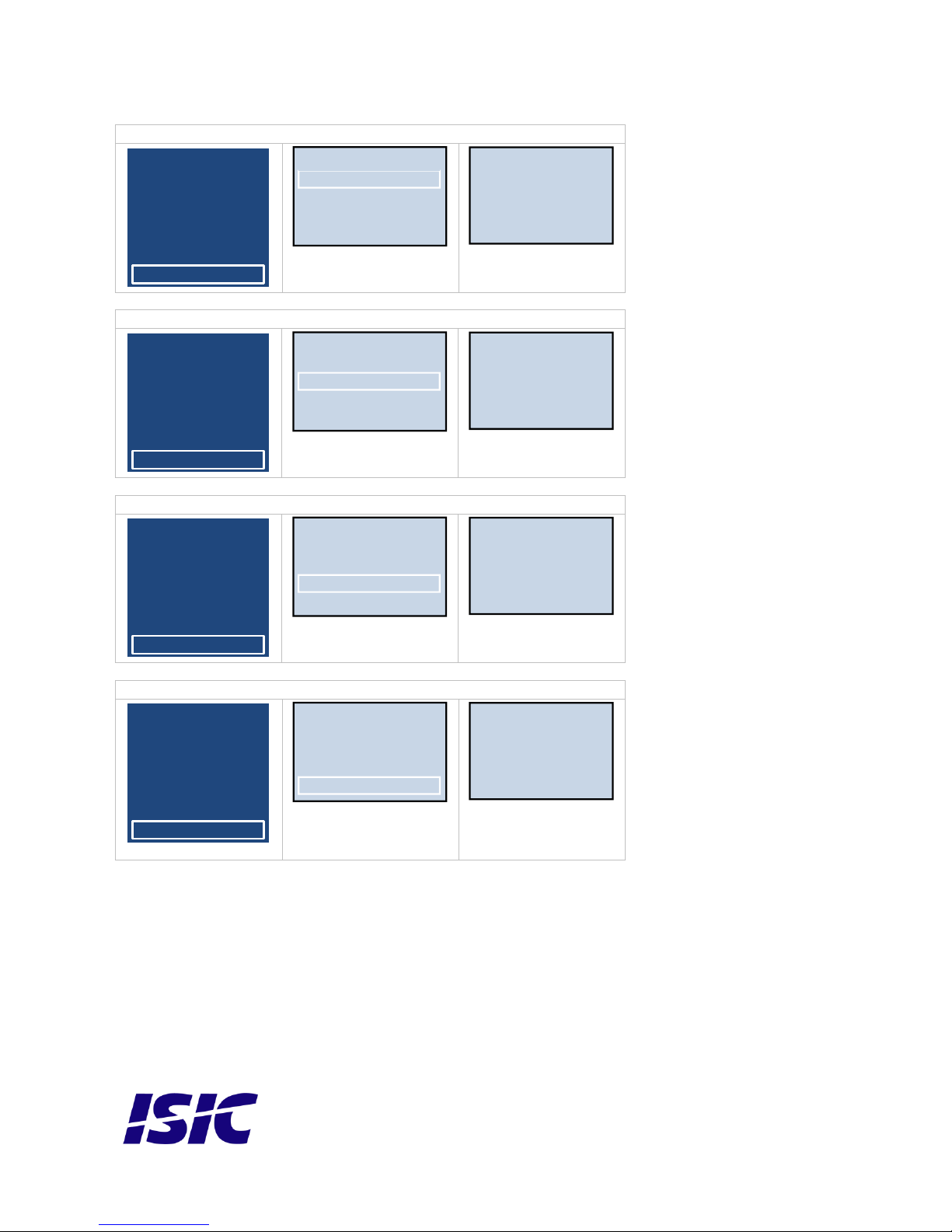
User Reference Manual – DuraMON GLASS series
PN: 08186-000 Rev B Page 20
Setup – Vertical
Main Menu
Picture
PIP PBP
Audio
Setup
Monitor Info
OSD Settings
Vertical 50
Transparency Off
OSD Time Out 20s
Upgrade Sw
Horizontal 50
Value from 0 to 100
Setup – Transparency
Main Menu
Picture
PIP PBP
Audio
Setup
Monitor Info
OSD Settings
Vertical 50
Transparency Off
OSD Time Out 20s
Upgrade Sw
Horizontal 50
Off
1
2
3
4
Setup – OSD Time Out
Main Menu
Picture
PIP PBP
Audio
Setup
Monitor Info
OSD Settings
Vertical 50
Transparency Off
OSD Time Out 20s
Upgrade Sw
Horizontal 50
5s
10s
20s
30s
60s
Setup – Upgrade SW
Main Menu
Picture
PIP PBP
Audio
Setup
Monitor Info
OSD Settings
Vertical 50
Transparency Off
OSD Time Out 20s
Upgrade Sw
Horizontal 50
On
Off
Page 21

User Reference Manual – DuraMON GLASS series
PN: 08186-000 Rev B Page 21
3 Troubleshooting
Problem
Cause
Solutions
No picture on display
Backlight level set to minimum
Increase backlight
Monitor turned off
Turn on the monitor
No input signal present
Apply signal
No power cord connected
Apply power
Buttons on front doesn’t work
Unit in ECDIS mode
Press Menu + Enter to unlock
the monitor
Keypad defect
Please do not try to open the
unit. Send it to ISIC A/S for
repair.
The unit will not turn on.
Unknown
Please do not try to open the
unit. Send it to ISIC A/S for
repair.
4 Servicing the unit
In case that the unit still fails after following the troubleshooting send the unit to ISIC for repair. There
are no user serviceable parts inside and to ensure ECDIS compliance the monitor has to be
recalibrated at ISIC.
5 Terms, Acronyms and abbreviations
Communication protocol:
Use a serial link to control various settings in the monitor
DVI-D:
Digital Visual Interface
ECDIS:
Electronic Chart Display and Information System
IP65:
International Protection Rating (dust tight and protected
against water jets)
OSD:
On Screen Display
VGA:
DP:
HDMI:
Video Graphics Array
Display Port
High-Definition Multimedia Interface
Page 22

User Reference Manual – DuraMON GLASS series
PN: 08186-000 Rev B Page 22
6 ISIC info / Support
In case you have inquiries or problems with your DuraMON GLASS, you have a number of
possibilities to get support.
Company name: ISIC A/S
Head office: Edwin Rahrs Vej 54
DK – 8220 Brabrand
Denmark
Shipping address: Holmstrupgaardvej 5
DK-8220 Brabrand
Denmark
Telephone: +45 70 20 70 77
Fax: +45 70 20 79 76
VAT number: DK 16 70 45 39
Bank Address: Handelsbanken A/S
Havneholmen 29
DK-1561 København V
Denmark
Bank Code: 0892
IBAN DKK: DK53 0892 0001 0159 69
IBAN EUR: DK48 0892 0003 0026 19
IBAN USD: DK26 0892 0003 0026 27
SWIFT: HANDDKKK
Support: Via homepage www.isic-systems.com under aftersales
By mail to [email protected]
During office-hours (Mo-Fr: CET 0800 - 1600) at +45 70 20 70 77
Service: Before shipment for service Request Return Material Authorization number at
homepage http://www.isic-systems.com/aftersales/tech-support-rma/
By mail to [email protected]
Page 23

User Reference Manual – DuraMON GLASS series
PN: 08186-000 Rev B Page 23
7 Revision history
Rev A
July 2017
First release
Rev B
September
Page 6, Corrected button drawing
Page 9, Mechanical outline updated
Page 10, Mechanical outline updated
Page 24
User Reference Manual – DuraMON GLASS series
PN: 08186-000 Rev B Page 24
8 Appendix A: Pixel policy
ISO 9241-307:2008 guidelines for LCD pixel defects
Introduction
TFT displays consist of a set number of pixels. Each pixel consists of 3 sub-pixels also called dots (one red, one blue
and one green). Every sub-pixel is addressed by its own transistor. As a result, the manufacturing of glass substrate is
very complex.
Due to the nature of this manufacturing process, occasional defects can occur. Pixel defects or failures cannot be fixed
or repaired and may occur at any stage during the service life of the TFT display.
To regulate the acceptability of defects and protect the end user, ISIC A/S complies with the ISO 9241-307:2008
standard. This standard recommends how many defects are considered acceptable in a display, before it should be
replaced within the terms of the warranty.
Monitor classification
ISO 9241-307:2008
Allowed defects per type per million pixels
Defect classes
Pixel defects
Cluster defect
Type 1
Type 2
Type 3 total
(2xN3a + N3b)
Type 1
Type 2
Type 3
Class: 0
0 0 0 0 0 0 Class: I
1 1 5 0 0 0 Class: II
2 2 10 0 0
1
Class: III
5
15
100 0 0
5
ISIC TFT monitors comply with ISO 9241-307:2008 Class II.
Special agreements about other classifications can be made between ISIC A/S and the customer.
Measurement method/monitoring conditions for pixel defects
In compliance with the ISO-9241-307:2008 standard, the following conditions are observed:
Final check for pixel fault undertaken right after burn-in, i.e. with pre-heating of the display.
Surrounding temperature 25ºC ± 5ºC
Relative air humidity 40–70%
Pixel definition
Every pixel consists of three sub-pixels/dots (red, blue, green).
Every sub-pixel has its own transistor.
The three sub-pixels/dots must be considered as one unit.
Page 25
User Reference Manual – DuraMON GLASS series
PN: 08186-000 Rev B Page 25
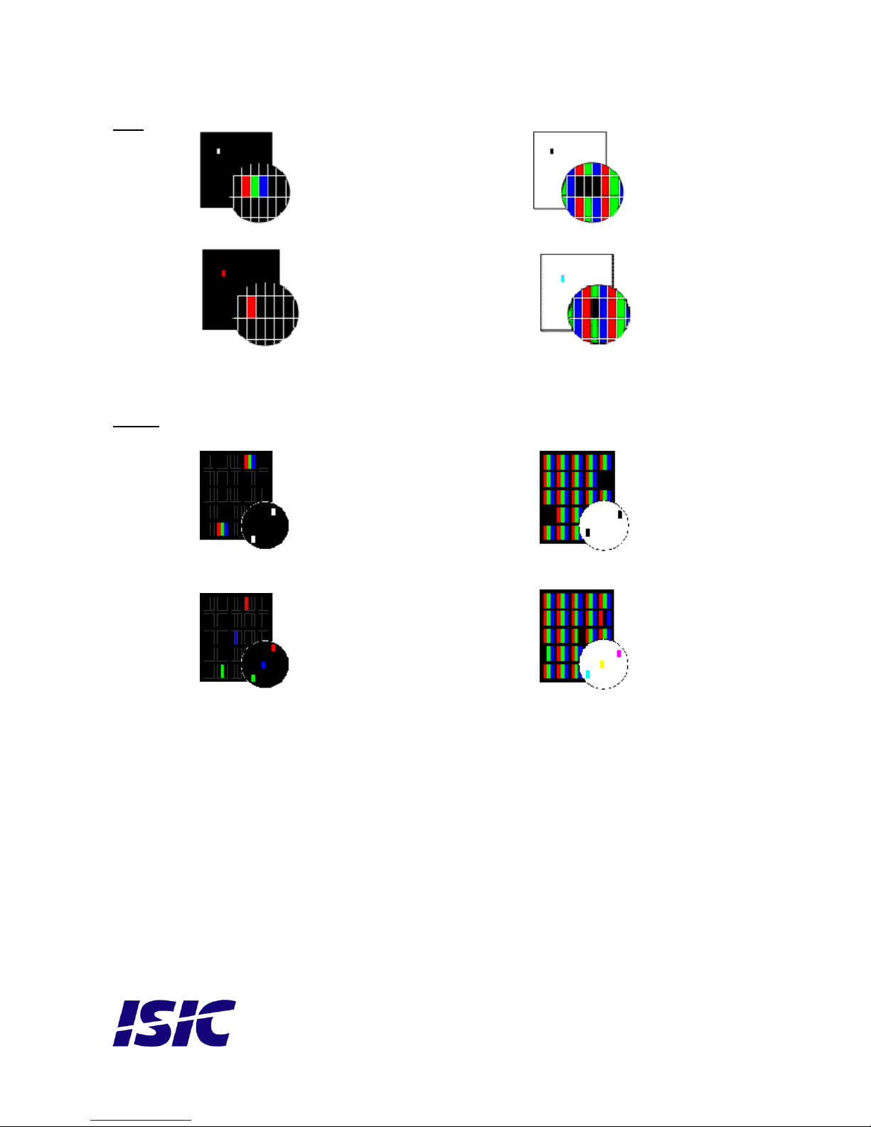
Pixel
Pixel defect type 1 Pixel constantly lit Pixel defect type 2 Pixel constantly dark
Pixel defect type 3a Pixel defect type 3b
Sub-pixel/dot (red, blue, green) constantly lit Sub-pixel/dot (red, blue, green) constantly dark
Cluster
A cluster consists of 5 x 5 pixels.
Cluster pixel defect type 1 Cluster pixel defect type 2
Pixels in a cluster area constantly lit Pixels in a cluster area constantly dark
Cluster pixel defect type 3a Cluster pixel defect type 3b
Sub-pixels/dots in a cluster area constantly lit Sub-pixels/dots in a cluster area constantly dark
Page 26
User Reference Manual – DuraMON GLASS series
PN: 08186-000 Rev B Page 26
Pixel faults accepted by ISIC A/S
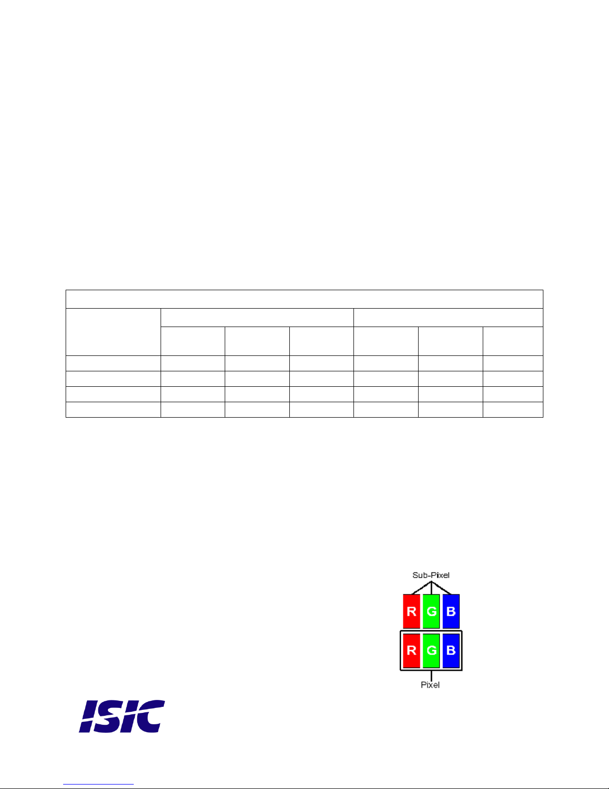
The maximum number of pixel faults that is considered acceptable at different screen resolutions is shown in the
table below.
This is the native resolution and not the resolution as adjusted by user.
Class II
Allowable number of pixel faults in monitor applications
Screen
type
Native
resolution
Number of
pixels
Pixel defect
type 1
Pixel defect
type 2
Pixel defect
Type 3 total
(2xN3a + N3b)
Cluster
defect type
1 and 2
Cluster
defect
type 3
WVGA
800x480
384,000
0 0 3
0
0
XGA
1024x768
768,432
1 1 7
0
0
WXGA
1280x800
1,024,000
2 2 10
0
1
SXGA
1280x1024
1,310,720
2 2 13
0
1
UXGA
1600x1200
1,920,000
3 3 19
0
1
FHD
1920x1080
2,073,600
4 4 20
0
2
WUXGA
1920x1200
2,304,000
4 4 23
0
2
UHD
3840x2160
8,294,400
16
16
83
0
8
Page 27

User Reference Manual – DuraMON GLASS series
PN: 08186-000 Rev B Page 27
Edwin Rahrs Vej 54
DK-8220 Brabrand
Denmark
Web: http://www.isic-systems.com
Email: [email protected]
 Loading...