


User Reference Manual
DuraMON15 LED
User Reference Manual – DuraMON15 LED
PN: 05587-000 Rev A Page 1

Disclaimer
ISIC A/S makes no representation or warranties with respect to the contents or use of this manual,
and specifically disclaims any express or implied warranties of merchantability or fitness for any
particular purpose. Further, ISIC A/S rese rves the rig h t to revise this p ublicatio n a n d to make
changes to its conte nt at any time, without obligation to notify any person or entity of such revisions
or changes.
Image sticking: If the monitor is operated with static images (logo’s etc) it will inevitably lead to
images sticking on the display (like on old CRT’s). This is not a permanently situation and can be
removed by operating the monitor with a completely black screen.
FCC Warning
Computing devices and peripherals generate and radiate radi o frequency energy, and if not
installed and used in accordance with the instructions advised by ISIC A/S, it may cause
interference to radio communication.
The DuraMON series, manufactured by ISIC A/S, is designed to comply with the emerging generic
EEC standards, that cover applications in maritime environment.
Classification
The monitor is classified as “protected from the weather” according to IEC 60945 ed.4 (former class
b).
Approvals
Approval according to IACS E10 ed. 5 and IEC 60945 ed. 4, Maritime na vi gation and radio
communication equipment and systems – General requi re m en ts.
ISIC A/S is complying with the WEEE directive within the European Union, stating that electronic and
electric products must be collected separately.
Products are marked according to the directive.
Copyright 2012 ISIC A/S
ISIC PN: 05587-000 rev. A
ISIC A/S
Edwin Rahrsvej 54
DK-8220 Brabrand
Denmark
Phone: +45 70 20 70 77
Fax: +45 70 20 79 76
Web: http://www.isic-systems.com
User Reference Manual – DuraMON15 LED
PN: 05587-000 Rev A Page 2

User Reference Manual – DuraMON15 LED
PN: 05587-000 Rev A Page 3
Table of Contents
1 FEATURES ............................................................................................................................................................... 4
2 GENERAL CONSIDERATIONS ON INSTALLATION AND OPERATION .................................................. 5
3 DURAMON CONNECTIONS ................................................................................................................................ 6
4 DURAMON FRONT PANEL CONTROLS .......................................................................................................... 6
5 OSD ............................................................................................................................................................................ 7
6 SERIAL CONNECTION PIN-OUT ..................................................................................................................... 11
7 DURAMON COMMUNICATION PROTOCOL ................................................................................................ 11
8 DDC/CI COMMANDS ........................................................................................................................................... 12
8.1 VCP FUNCTIONS ................................................................................................................................................ 12
9 TECHNICAL SPECIFICATIONS DURAMON15 LED .................................................................................... 13
10 MECHANICAL OUTLINE DURAMON15 LED ............................................................................................ 14
11 COMPASS SAFE DISTANCE .......................................................................................................................... 15
12 POWER CONSUMPTION ................................................................................................................................ 15
13 TROUBLESHOOTING ..................................................................................................................................... 15
14 SERVICING THE UNIT ................................................................................................................................... 15
15 TERMS, ACRONYMS AND ABBREVIATIONS ........................................................................................... 16
16 ISIC INFO / SUPPORT ..................................................................................................................................... 17
17 REVISION HISTORY ....................................................................................................................................... 18
18 APPENDIX A: PIXEL POLICY ....................................................................................................................... 19

User Reference Manual – DuraMON15 LED
PN: 05587-000 Rev A Page 4
1 Features
Congratulations on your purchase of a DuraMON product. This short form manual is designed to get
you started working with your new DuraMON.
The DuraMON series of monitors are all made as rugged monitors especially designed for the
demanding operating conditions at sea.
The DuraMON series are tested for full comp liance to marine-standards IACS E10 and IEC 60945.
The monitor comes with excellent brightness and contrast levels that ensure a good readability thus
making it very eye-friendly. For the best picture quality, always use a double shielded DVI cable
with ferrites, like the one supplied with the monitor.
Backlight LED technology
Direct dimming control (0-100%) from UP/DOWN buttons.
Full settings control via menu and limited settings over serial link or DDC.
Anti-glare coated glass.
IP65 protection and liquid resistant front.
It is important to notice that, when powered off, the product still consumes some power from the
mains. To cut off the power from the product it is necessary to unplug its power cord from the
mains.

User Reference Manual – DuraMON15 LED
PN: 05587-000 Rev A Page 5
2 General considerations on Installation and
Operation
The DuraMON is designed to work at conditions according to IEC 60945. However, keeping the
temperature and vibration level at a minimum will extend the life time of the product. ISIC
recommend operating this product at normal room temperature (20-25 ° C ), with the lowest level of
vibration and humidity.
Installation of the DuraMON
In order to obtain the best possible operating conditions, please note the following precautions.
- Room for cooling.
When designing the cabinet/console for the Dur a MON, please ensure that air can flow
freely around the cabinet, in order to avoid any unnecessary rise in temperature. If it is
not possib le to have an adequate natural airflow, use a fan to force the airflow to be
higher.
- Mounting positions
To obtain adequate cooling by convection ISI C r e c o mmends tha t the DuraMON is
mounted at least 30 degrees from horizontal. If this is not possible, forced cooling must
be applied directly to the unit in order not to overheat it.
- Sunlight
If the unit can be exposed to direct sunlight, there is a potential risk that the unit can be
overheated. Please take measures to prevent direct sunlight. Do also consider forced
cooling on the back of the unit.

3 DuraMON connections
Below is a view of connections to the monitor. The default inpu ts are: power, RS-232, DVI and
VGA.
RS‐232 VGA DVI POWER
4 DuraMON front panel controls
ON/OFF LED MENU DOWN UP ENTER
ON/OFF:
This button is used to turn the product on or off. Pressing it will toggle the power.
.
LED:
The LED will change color from green to red to indicate power down. LED brightness will decrease
with decreasing backlight brightness.
If there is no active input signal, the monitor will display a dialog box to inform the user to check the
signal cable.
MENU:
Pressing this button the OSD menu will appear. See OSD section for details.
UP/DOWN:
Used to adjust backlight brightness or to navigate and adjust settings in menus.
ENTER:
This button is used to confirm selections in the OSD menu. If Source isn’t set to AUTO in the OSD, use
this button to switch to an active source.
User Reference Manual – DuraMON15 LED
PN: 05587-000 Rev A Page 6

5 OSD
With the OSD (On Screen Display) you can modify the setti ngs and control the special features of
the DuraMON as described on the next pages.
To enter the OSD press “MENU” button.
To navigate the OSD use the “UP” and “DOWN” buttons and press “ENTER” to select a specific
setting. To return a previous menu point, press the “MENU” button.
PICTURE
Brightness:
Use to adjust the Backlight Brightness.
Increasing the value will increase the
luminance. Decreasing it will decrease the
luminance. Be aware that low luminance
may inhibit visibility of information on the
screen, particularly at night.
Default value = 90
Contrast:
Use to adjust the Contrast. Increasing the
value will increase the visibility of dark
details in the picture. Decreasing the value
will decrease the visibility of dark details in
the picture. Be aware that too high or low
contrast may inhibit visibility of information
on the screen, particularly at night.
Default value = 50
Sharpness:
Use to adjust the Sharpness of the picture.
Increasing the value will make the picture
more detailed. Decreasing the value will
make the picture less detailed.
Default value = 2
H Position (VGA only):
Use to adjust the pos ition of the signal left
or right. Increase the value to move the
picture right. Decrease the value to move
the picture left.
Default value = 50
V Position (VGA only):
Use to adjust the pos ition of the signal up
or down. Increase the value to move the
picture up. Decrease the value to move
the picture down.
Default value = 50
User Reference Manual – DuraMON15 LED
PN: 05587-000 Rev A Page 7

Clock (VGA only):
Use to adjust the frequency of the clock
signal.
Default value = 50
Phase (VGA only):
Use to adjust the clock phase. Adjusting
this value will remove shadows in the
picture.
Default value = Auto detected
COLOR
Color Status Management
Use to adjust the color temperature of the
picture.
Default value = User
Red (VGA only):
Use to adjust the Red gain. Increase the
value to make the picture more reddish.
Decrease to make it less reddish.
Default = 50
Green (VGA only):
Use to adjust the Green gain. Increa se the
value to make the picture more greenish.
Decrease to make it less greenish.
Default = 50
Blue (VGA only):
Use to adjust the Blue gain. Increase the
value to make the picture more bluish.
Decrease to make it less bluish.
Default = 50
Auto Color (VGA only):
Use to auto adjust the ADC values for Red,
Green and Blue.
User Reference Manual – DuraMON15 LED
PN: 05587-000 Rev A Page 8

OSD
Language:
Use to change the OSD language.
Default: English
H Position:
Use to adjust the pos ition of the OSD menu
left or right. Increase the value to move the
OSD right. D ec r ease the value to m o v e t h e
OSD left.
Default value = 50
V Position:
Use to adjust the pos ition of the OSD menu
up or down. Increase the value to move
the OSD up. Decrease the value to move
the OSD down.
Default value = 50
Transparency:
Use to adjust the transparency of the OSD
menu. Decreasing the value will make the
OSD more tr a n s p a rent. Incr e asing the
value will make the OSD more solid.
Default value = 33
OSD Time:
Use to select how long time the OSD menu
will be displayed. When no actions have
been carried out in the specified time, the
OSD menu will be removed.
Default value = 10 seconds
SETUP
Source:
Use to change the active source. Selecting
AUTO will scan for an active signal. If both
VGA and DVI signal are found, DVI will be
preferred.
Default = Auto
Factory Reset:
Use to restore all settings to the default
values. By activating this function, all
settings made by the user will be lost and
the monitor will be brought back to known
operating conditions.
User Reference Manual – DuraMON15 LED
PN: 05587-000 Rev A Page 9

User Reference Manual – DuraMON15 LED
PN: 05587-000 Rev A Page 10
Aspect:
Use to select if aspect ratio should be
applied to the picture. Off will s tretch the
picture to fill the screen. On will fill the
screen, but keep the aspect ratio. This will
result in black bands on the border of the
screen.
Default = Off
Set ID:
Use to enable/disable serial
communication through the RS-232 port.
Enabling it will allow th e user to control
settings in the monitor. See the “DuraMON
communication protocol” section for
details.
Default = Off

User Reference Manual – DuraMON15 LED
PN: 05587-000 Rev A Page 11
6 Serial connection pin-out
The pin-out of the serial port SUB-D connector on the rear side of the DuraMON is as below:
Pin
RS-232
SUB-D 9-pol female
1
2 TX
3 RX
4
5 GND
6
7
8
9
7 DuraMON communication protocol
To control the DuraMON from a PC the commands below has to be used.
Function BYTE0 BYTE1 BYTE2 BYTE3 BYTE4 BYTE5
Length Set ID CMD1 CMD2 CMD3 Checksum
POWER BUTTON Power On/Off 6 0 ‘K’ (0x4B) ‘P’ (0x50) ‘W’ (0x57) 0x08
MENU BUTTON Menu/Exit 6 0 ‘K’ (0x4B) ‘M’ (0x4D) ‘N’ (0x4E) 0x14
ENTER BUTTON Enter 6 0 ‘K’ (0x4B) ‘M’ (0x4D) ‘O’ (0x4F) 0x13
UP BUTTON Up 6 0 ‘K’ (0x4B) ‘M’ (0x4D) ‘U’ (0x55) 0x0D
DOWN BUTTON Down 6 0 ‘K’ (0x4B) ‘M’ (0x4D) ‘D’ (0x44) 0x1E
Checksum : BYTE0 + BYTE1 + BYTE2 + BYTE3 + BYTE4 + BYTE5 = 0
Example:
Decrement backlight level one step (when no OSD is active):
BYTE0 BYTE1 BYTE2 BYTE3 BYTE4 BYTE5
0x06 0x00 0x4B 0x4D 0x44 0x1E
Reply from Monitor:
BYTE0 BYTE 1 BYTE2 BYTE3 BYTE4 BYTE5
0x64 0x6F 0x77 0x6E 0x0D 0x0A

User Reference Manual – DuraMON15 LED
PN: 05587-000 Rev A Page 12
8 DDC/CI commands
To avoid the additional serial cable it is also possible to control the DuraMON through a DDC/CI
(Display Data Channel Command Interface) integrated in the DVI cable/connector.
Data format:
BYTE0 BYTE 1 BYTE2 BYTE3 BYTE4 BYTE5 BYTE6 BYTE7
DEST SOURCE LENGHT SET_VCP VCP R/W VALUE CHK
DEST Destination address
SOURCE Source address
LENGTH Length
SET_VCP Set VCP Featur e COMMAND
VCP VCP command to use
R/W Read or Write
VALUE Value
CHK Checksum
8.1 VCP functions
VCP 10h (Backlight brightness)
Value range: 0x00 – 0x5A
Example:
Set Backlight brightness to 0x5A (90%):
BYTE0 BYTE 1 BYTE2 BYTE3 BYTE4 BYTE5 BYTE6 BYTE7
0x6E 0x51 0x84 0x03 0x10 0x00 0x5A 0xF2
VCP 12h (Contrast)
Value range: 0x00 – 0x64
Example:
Set Contrast to 0x32 (50%):
BYTE0 BYTE 1 BYTE2 BYTE3 BYTE4 BYTE5 BYTE6 BYTE7
0x6E 0x51 0x84 0x03 0x12 0x00 0x32 0x98

9 Technical specifications DuraMON15 LED
DuraMON LED
Display sizes:
Display properties:
Standard Display:
Wide angle Display option:
15” LCD (TFT)
Size – Active area (Aspect) Luminance Contrast Resolution View angle
(L/R/T/B)
15” - 304 x 228 mm (4/3) 400 Cd/m2 700:1 1024 x 768 80/80/80/60
15” - 304 x 228 mm (4/3) 350 Cd/m2 1000:1 1024 x 768 85/85/85/85
Materials: Front: Sea Water Resistant Aluminium w. black power coating RAL 9005
Rear: Sea Water Resistant Aluminium w. black power coating RAL 9005
Window: Anti Reflection coated front glass
Protection: IP65 front – IP20 rear
DuraMON LED I/O
Video inputs:
RGB : Analogue 0.7 Vpp positive at 75Ω
,
Separate sync or sync on green
Generally all VESA compatible video modes are supported up to
165MHz (up to UXGA 60Hz and WUXGA 60Hz reduced
blanking).
Horizontal sync: 15-100 kHz (automatic)
Vertical sync: 30-85 Hz up to 1280x1024
30-60 Hz up to 1920x1200
DVI: Generally all VESA compatible video modes are supported up to
160MHz (up to UXGA 60Hz and WUXGA 60Hz reduced blanking).
Special modes supported on request.
Option available for extra DVI, RGB (in/out) and/or S-video and Composite video
Control inputs: 1x RS232 – for remote control
Option available for Touch 1x RS232
User Reference Manual – DuraMON15 LED
PN: 05587-000 Rev A Page 13
DuraMON LED Power Supply Options
Standard: 90-264Vac. 50-60Hz Input
Optional:
Power Consumption:
18-36Vdc Input
Size P
TYP
(Watt) P
MAX
(Watt)
15” 20
35
DuraMON LED Environmental Conditions
Operating Temperature: -15 to 55 °C
Storage Temperature: -25 to 70 °C
Relative Humidity: 8 to 90 %
DuraMON LED Approvals
CE Mark: EN61000-6-2 & EN61000-6-4
Marine: IACS E10 Rev. 5 & IEC 60945 Ed. 4
For marine class approvals – see www.isic-systems.com
DuraMON LED Physical dimensions
2 page flyer rev. 3.12.2012. Technical specifications are subject to
chan
g
e without
p
rior notice. For drawin
g
s and full technical
Size:
406 (W) x 342 (H) x 64 (D)
Weight: 4.1 kg.
Bracket: Desk / wall / roof bracket and IP22 rear-cover available (optional extra)
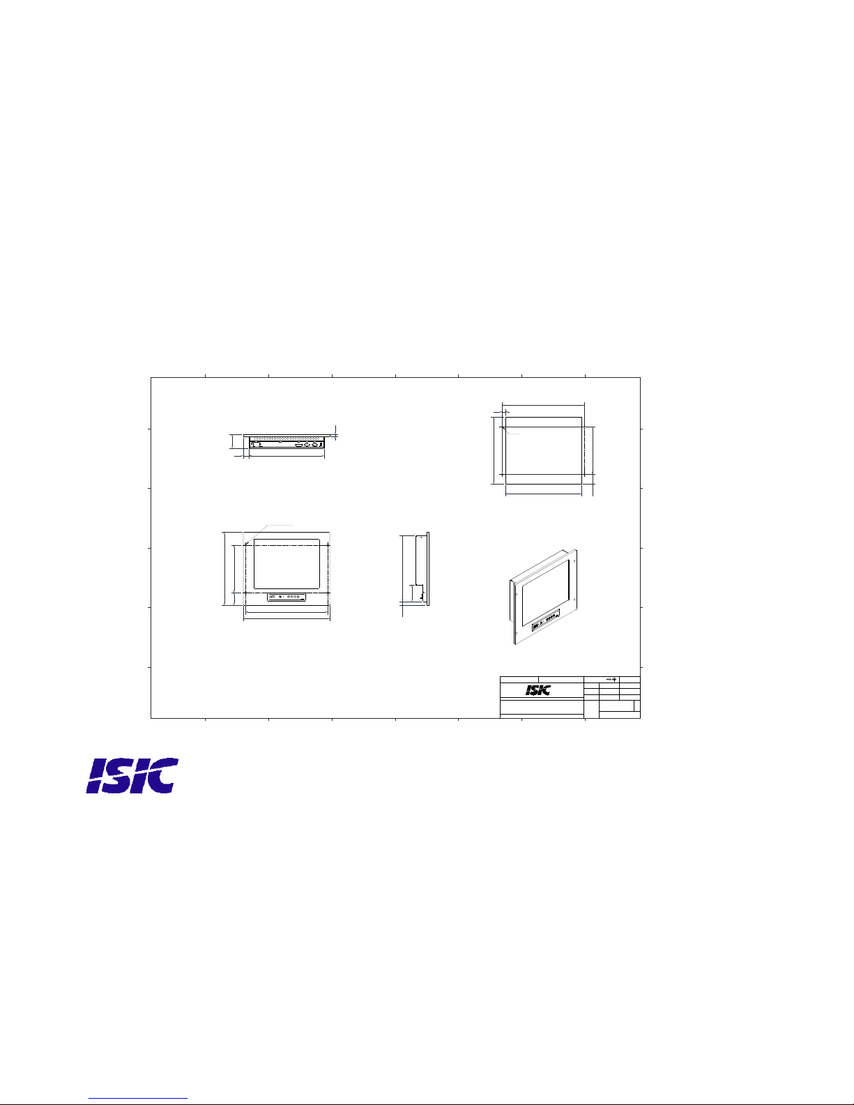
10 Mechanical outline DuraMON15 LED
406
Recommended panel cut out
4 x M6
4 x n7
v n12 x 6,5
1
1
2
2
3
3
4
4
5
5
6
6
7
7
8
8
A A
B B
C C
D D
E E
F F
Approved by
Projection method:
Drawing size:
Units: mm
Designed by
General tolerances:
`0,2
Hole position:
`0,1
Scale:
Drawing no.
Replaces:
Rev.Subject:
ISIC A/S, Edwin Rahrs Vej 54, DK-8220 Brabrand. Tlf.: +45 7020707 7. Web: www.isic.dk
This docoment contains propri etary information and is not to be
used or reproduced without the wri tten permission of ISIC A/S
Angle, straightness and flatness: DS/ISO 2768-H
pas
29-02-2012
A2
Mechanical outline 15'' DuraMON LED
PAS 01-10-2012
1:4
05536-000
A
342
222
386
60
63,9
10
352
27
309
80
16,5
356
313
45,5
222
386
15
User Reference Manual – DuraMON15 LED
PN: 05587-000 Rev A Page 14

User Reference Manual – DuraMON15 LED
PN: 05587-000 Rev A Page 15
11 Compass safe distance
Test object / condition Minimum Compass safe
distance [cm]
(5.4°/H deviation or a
horizontal magnetic flux of
0.094µT)
Minimum Compass safe
distance [cm]
(18°/H deviation or a horizontal
magnetic flux of 0.313µT)
DuraMON15 LED 165 110
12 Power Consumption
Test object / condition Ptyp
Pmax
DuraMON15 LED 20 35
In rush current ac: 100A max at 240 VA C.
13 Troubleshooting
Problem Cause Solutions
No picture on display Backlight level set to mini mum Increase backlight
Monitor turned off Turn on the monitor
No input signal present Apply signal
No power cord connected Apply power
Buttons on front doesn’t work No power cord connected Apply power
Keypad defect Please do not try to open the
unit. Send it to ISIC A/S for
repair.
14 Servicing the unit
In case that the unit still fails after following the troubleshooting send the unit to ISIC for repair. There
are no user serviceable parts inside.

User Reference Manual – DuraMON15 LED
PN: 05587-000 Rev A Page 16
15 Terms, Acronyms and abbreviations
Communication protocol: A serial link to control various settings in the monitor
DVI: Digital Visual Interface
IP20: International Protection Rating (protected against objects with
a size larger than 12.5mm)
IP65: International Protection Rating (dust tight and protected
against water jerks)
OSD: On Screen Display
VGA: Video Graphics Array

User Reference Manual – DuraMON15 LED
PN: 05587-000 Rev A Page 17
16 ISIC info / Support
In case you have inquiries or problems with your DuraMON, you have a number of possibilities to
get support.
Company name: ISIC A/S
Head office: Edwin Rahrs Vej 54
DK – 8220 Brabrand
Denmark
Shipping address: Holmstrupgaardvej 5
DK-8220 Brabrand
Denmark
Telephone: +45 70 20 70 77
Fax: +45 70 20 79 76
Mail: mail@isic-systems.com
www: www.isic-systems.com
VAT number: DK 16 70 45 39
Bank Name/Address: Handelsbanken A/S
Havneholmen 29
DK – 1561 København V
Denmark
Bank Code: 0892
SWIFT: HANDDKKK
IBAN for DKK: DK53 0892 0001 0159 69
IBAN for EUR: DK48 0892 0003 0026 19
IBAN for USD: DK26 0892 0003 0026 27
Contacts:
RFQ’s: By fax to +45 70 20 79 76
By mail to sales@isic-systems.com
Orders: By fax to +45 70 20 79 76
By mail to orders@isic-systems.com
Support: Via homepage www.isic-systems.com
under aftersales
By mail to service@isic-systems.com
During office-hours (Mo-Fr: CET 0800 - 1600) at +45 70 20 70 77
Service: Before shipment for service Request Return Material Authorisation number
at homepage www.isic-systems.com
under RMA
By mail to service@isic-systems.com

User Reference Manual – DuraMON15 LED
PN: 05587-000 Rev A Page 18
17 Revision history
Rev A Dec 2012 Release

18 Appendix A: Pixel policy
ISO 9241-307:2008 guidelines for LCD pixel defects
Introduction
TFT displays consist of a set number of pixels. Each pixel consists of 3 sub-pixels also called dots (one red,
one blue and one green). Every sub-pixel is addressed by its own transistor. As a result, the manufacturing
of glass substrate is very complex.
Due to the nature of this manufacturing process, occasional defects can occur. Pixel defects or failures
cannot be fixed or repaired and may occur at any stage during the service life of the TFT display.
To regulate the acceptability of defects and protect the end user, ISIC A/S complies with the ISO 9241307:2008 standard. This standard recommends how many defects are considered acceptable in a display,
before it should be replaced within the terms of the warranty.
Monitor classification
ISO 9241-307:2008
Allowed defects per type per million pixels
Defect classes
Pixel defects Cluster defect
Type 1 Type 2
Type 3 total
(2xN
3a
+ N3b)
Type 1 Type 2 Type 3
Class: 0 0 0 0 0 0 0
Class: I 1 1 5 0 0 0
Class: II 2 2 10 0 0 1
Class: III 5 15 100 0 0 5
ISIC TFT monitors comply with ISO 9241-307:2008 Class II.
Special agreements about other classifications can be made between ISIC A/S and the customer.
Measurement method/monitoring conditions for pixel defects
In compliance with the ISO-9241-307:2008 standard, the following conditions are observed:
• Final check for pixel fault undertaken right after burn-in, i.e. with pre-heating of the display.
• Surrounding temperature 25ºC ± 5ºC
• Relative air humidity 40–70%
Pixel definition
Every pixel consists of three sub-pixels/dots (red, blue, green).
Every sub-pixel has its own transistor.
The three sub-pixels/dots must be considered as one unit.
User Reference Manual – DuraMON15 LED
PN: 05587-000 Rev A Page 19

Pixel
Pixel defect type 1 Pixel constantly lit Pixel defect type 2 Pixel constantly dark
Pixel defect type 3a Pixel defect type 3b
Sub-pixel/dot
(red, blue, green) constantly lit Sub-pixel/dot (red, blue, green) constantly dark
Cluster
A cluster consists of 5 x 5 pixels.
Cluster pixel defect type 1 Cluster pixel defect type 2
Pixels in a cluster area constantly lit Pixels in a cluster a rea constantly dark
Cluster pixel defect type 3a Cluster pixel defect type 3b
Sub-pixels/dots in a cluster area constantly lit Sub-pixels/dots in a cluster area constantly dark
User Reference Manual – DuraMON15 LED
PN: 05587-000 Rev A Page 20

User Reference Manual – DuraMON15 LED
PN: 05587-000 Rev A Page 21
Pixel faults accepted by ISIC A/S
The maximum number of pixel faults that is considered acceptable at different screen resolutions is shown in
the table below.
This is the native resolution and not the resolution as adjusted by user.
Class II
Allowable number of pixel faults in monitor applications
Screen
type
Native
resolution
Number of
pixels
Pixel defect
type 1
Pixel defect
type 2
Pixel defect
Type 3 total
(2xN
3a
+ N3b)
Cluster
defect type
1 and 2
Cluster
defect
type 3
XGA 1024x768 768,432 1 1 7 0 0
SXGA 1280x1024 1,310,720 2 2 13
0 1
UXGA 1600x1200 1,920,000 3 3 19 0 1
FHD 1920x1080 2,073,600 4 4 20
0 2
WUXGA 1920x1200 2,304,000 4 4 23
0 2

Edwin Rahrs Vej 54
DK-8220 Brabrand
Denmark
Web: http://www.isic-systems.com
Email: service@isic-systems.c om
User Reference Manual – DuraMON15 LED
PN: 05587-000 Rev A Page 22
 Loading...