

ISHIDA BC-300 Service Manual

Retail Scale
BC-3000
SERVICE MANUAL
Manual No. 0141A
ISHIDA CO., LTD.
48775

Contents
HARDWARE SECTION
1. INTRODUCTION ................................................................................................. 1-1
1.1 Main Components .................................................................................................. 1-1
1.2 Characteristics........................................................................................................ 1-2
2. SET UP................................................................................................................ 2-1
2.1 Parts Check ............................................................................................................ 2-1
2.2 Installation Site Check ............................................................................................ 2-1
2.3 Assembly ................................................................................................................ 2-1
2.4 Set Up Sequence ................................................................................................... 2-2
3. PARTS DISASSEMBLY & REPLACEMENT ...................................................... 3-1
3.1 Disassembly View and Part Names ....................................................................... 3-1
3.2 Upper Cover Removal ............................................................................................3-3
3.3 Circuit Board Replacement.....................................................................................3-6
3.4 Display Unit Replacement ...................................................................................... 3-7
3.5 Load Cell Replacement .......................................................................................... 3-8
4. ELECTRONIC CONFIGURATIONS.................................................................... 4-1
4.1 Connector Configuration.........................................................................................4-1
4.2 Power Unit .............................................................................................................. 4-2
4.3 Main Board (P-864) ................................................................................................ 4-3
4.4 A/D Board (P-830) .................................................................................................. 4-5
4.5 Keyboard ................................................................................................................ 4-5
4.6 Display Unit (P-856) ............................................................................................... 4-6
4.7 DC/DC Converter ................................................................................................... 4-7
4.8 Connector Bracket.................................................................................................. 4-7
4.9 Label Sensor .......................................................................................................... 4-8
5. THERMAL HEAD ................................................................................................ 5-1
5.1 Overview.................................................................................................................5-1
5.2 Specifications ......................................................................................................... 5-1
5.3 Thermal Head Adjustment...................................................................................... 5-2
5.4 Thermal Head Cleaning.......................................................................................... 5-3
5.5 Other Adjustments (Label sensor).......................................................................... 5-3
6. TROUBLESHOOTING ........................................................................................ 6-1
6.1 Periodic Parts Replacement (MTBF*) .................................................................... 6-1
6.2 Malfunction Troubleshooting Chart......................................................................... 6-2
6.3 Error Messages ...................................................................................................... 6-3
BC-3000
• Service Manual • Rev. 1 Contents - i

SOFTWARE SECTION
S1. OUTLINE OF SOFTWARE................................................................................ S1-1
S1.1 Memory Map.........................................................................................................S1-1
S2. PRINT FORMAT MODIFICATION..................................................................... S2-1
S2.1 Print Format Overview..........................................................................................S2-1
S2.2 Label Format Modification Range.........................................................................S2-1
S2.3 Format Modification Method .................................................................................S2-1
S3. DISPLAY MODULE ........................................................................................... S3-1
S3.1 Display Module Overview .....................................................................................S3-1
S3.2 Root and SUB Menu Selection.............................................................................S3-1
S4. SETTING MODE ............................................................................................... S4-1
S4.1 Menu Schematic...................................................................................................S4-1
S4.2 Setting Procedures ...............................................................................................S4-3
1. Label Format (b01) ........................................................................................S4-3
2. Bar Code (b02) ..............................................................................................S4-4
3. Code (b03).....................................................................................................S4-4
4. Initial Data Setting (b04) ................................................................................S4-5
5. PLU File (b08) ...............................................................................................S4-6
6. Registration Select (b11) ...............................................................................S4-7
7. Total Mode Select (b12).................................................................................S4-8
8. Password (b13) .............................................................................................S4-8
9. Default PLU (b14)..........................................................................................S4-8
S5. TEST MODE...................................................................................................... S5-1
S5.1 Menu Schematic...................................................................................................S5-1
S5.2 Test Mode Procedures..........................................................................................S5-2
1. Hardware Test (C01) (Calibration) .................................................................S5-2
2. RAM Clear (C02) ...........................................................................................S5-6
3. Thermal Head (C03)......................................................................................S5-7
4. Sensor Check (C04) ......................................................................................S5-8
5. Memory Check (C05) ....................................................................................S5-9
6. ROM Switch Number Select (C06)................................................................S5-9
7. Label Format (C07) .....................................................................................S5-10
8. Sales Mode (C08)........................................................................................S5-11
10. Preset Function Key (C10) ..........................................................................S5-12
99. Data Send/Load (C99).................................................................................S5-13
S6. IF-21FD ERRORS .............................................................................................S6-1
A1. DC/DC Converter Schematic Diagram............................................... Appendix-1
A2. P-864A Circuit Diagram....................................................................... Appendix-3
A3. BC to BC System Setup...................................................................... Appendix-5
A4. Korean Language Firmware ............................................................... Appendix-7
A5. Chinese/Japanese Language Firmware ............................................Appendix-9
A6. Label Format Worksheets ................................................................. Appendix-11
A7. Dual Weight Range Notice................................................................ Appendix-19
Contents - ii
BC-3000
• Service Manual • Rev. 1

HARDWARE SECTION

1INTRODUCTION
1.1 MAIN COMPONENTS
Chapter 1. Introduction
BC-3000
• Service Manual • Rev. 1 1 - 1

Chapter 1. Introduction
1.2 CHARACTERISTICS
■ 16-Bit microprocessor
The BC-3000 scale is equipped with a 16-bit microprocessor unit (V-40) which enables processing of large
quantities of data.
■ E2ROM
The use of E2ROM ensures that important data is not lost.
■ Resistance value and printing density settable via key entry
The thermal head resistance value as well as printing density can be set by key entry.
■ Settable sales mode
For supermarket specifications, there are operator and non-operator selections.
Differences from the AC-2000
• Data transmission to the IF-21FD is via I2NET (9P) instead of RS-232C used by the AC-2000.
• An inspection mode has been added. Verification can be made during totaling.
Mode Key Function
Enter the pass code (4 digits), then press MODE to change modes. If MODE is pressed without
entering a pass code, then normal operation mode is returned.
Pass Code Mode
9000 Registration
8000 Totals
7000 Subtraction
6000* Setting
5000* Checking
*Fixed
1 - 2
BC-3000
• Service Manual • Rev. 1

2 SET UP
2.1 PARTS CHECK
Open the shipping carton and confirm the following:
• No parts are missing.
• No parts are damaged.
2.2 INSTALLATION SITE CHECK
Check that the installation site conforms to the following conditions:
• Site is stable and level.
• Scale will not be exposed to water or other liquids.
• Scale will not be exposed to direct sunlight for long periods.
• Scale will not be exposed to wind or strong vibration.
• Installation site should be sufficiently spacious.
• Dedicated, grounded circuit is available.
Chapter 2. Set Up
2.3 ASSEMBLY
Assemble the display components as follows:
1. Thread the display connector cable through the display pole.
2. Attach display pole to the plastic display housing with 2 screws (M4).
3. Connect cables.
4. Attach the display to the main body with 2 screws (M4).
5. Cover the screws with the plastic screw caps.
BC-3000
• Service Manual • Rev. 1 2 - 1

Chapter 2. Set Up
2.4 SET UP SEQUENCE
1. Perform RAM clear sequence.
Insert the power plug into an outlet. Referring to Chapter S5 (Test Mode 2: RAM Clear), initialize all the
RAM data.
2. Set print format, label length and sales mode according to user's specifications.
Service manual reference sections:
• Print format setting : Chapter S5 (Test Mode7: Label Format)
• Label length setting : Chapter S4 (Setting Mode 1: Label Format)
• Sales mode setting : Chapter S5 (Test Mode 8: Sales Mode)
3. Register date and time.
Referring to the programming manual, enter the date and time.
4. Register PLU.
Referring to the programming manual, enter PLU data registration in Registration mode.
5. Perform print test.
Load a roll of labels or receipts, and confirm that printing is correct. Refer to Chapter S5 (Test Mode 3:
Thermal Head).
6. Perform totals clear.
Refer to the operation manual.
7. Back up data.
Back up the registration data on a floppy disk. Refer to Chapter S5 (Test Mode 99: Data Transmission.)
2 - 2
BC-3000
• Service Manual • Rev. 1
Chapter 3. Parts Disassembly & Replacement
3PARTS DISASSEMBLY & REPLACEMENT
This chapter explains the procedures for disassembling and replacing the main components. Please be
careful not to drop or strongly impact fragile parts such as the display unit and circuit boards. Also, before
disassembly, be sure to turn off the power switch and unplug the power cord.
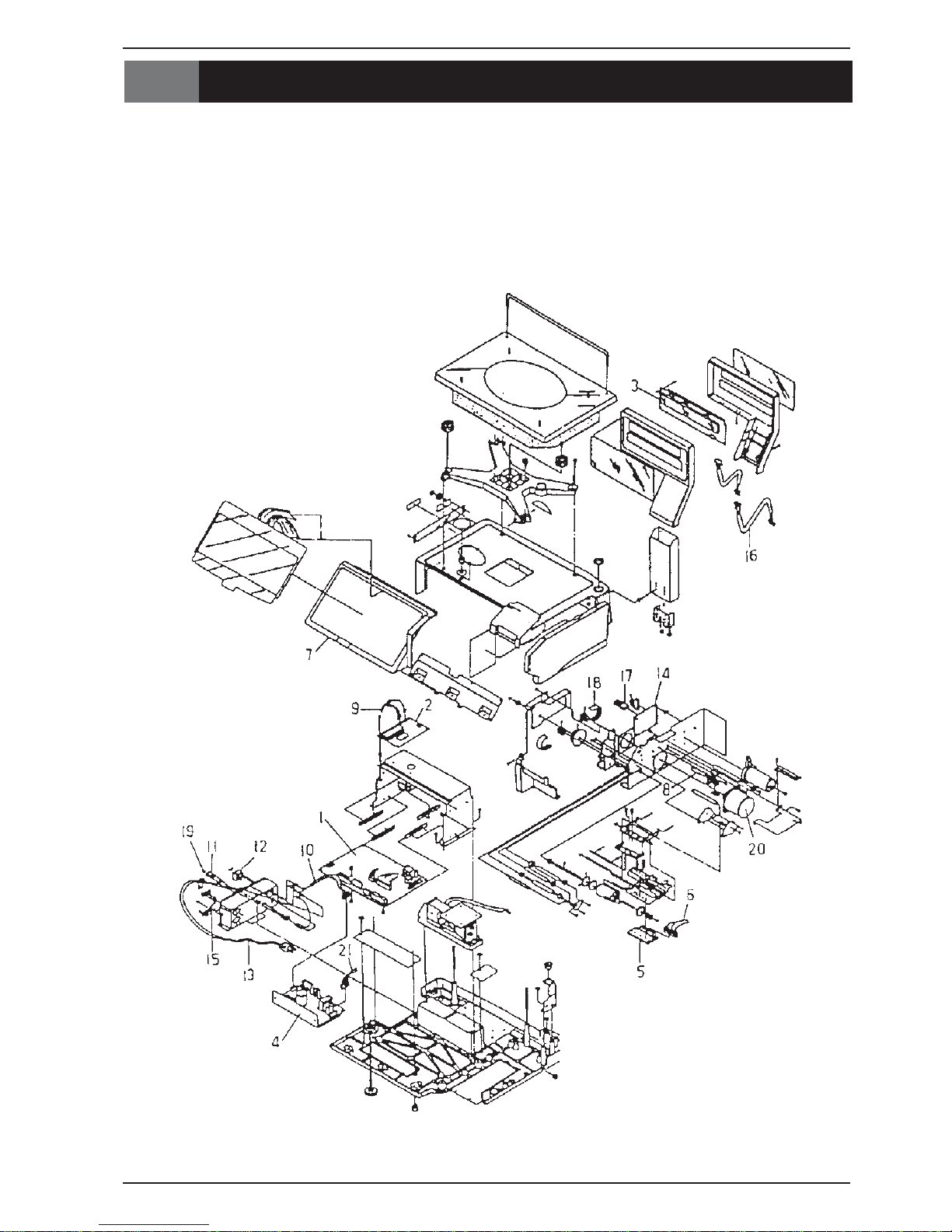
3.1 DISASSEMBLY VIEW AND PART NAMES
BC-3000
• Service Manual • Rev. 1 3 - 1
Chapter 3. Parts Disassembly & Replacement
*1UPC:468-P:BWP
2D/A:038-P:BWP
3yalpsiD:568-P:BWP
*4gnihctiwS:ylppuSrewoP
5daehlamrehT
6daehlamrehT:2S:ssenraH
7draobyeK:lenaP
8SA:rosneSlebaL
9elacS:3C:ssenraH
01rewoP:3C:ssenraH
11SA:esuF
21waseeS:hctiwS
Part Name Key
.oNtraPemaNtraP
*31drocrewoP:3C:ssenraH
41CD/CD:ylppuSrewoP
51I:3C:ssenraH
2
TEN
611yalpsiD:2C:ssenraH
711CD/CD:2S:ssenraH
81)Lx421(LX:tleBgnimiT
*91ebutssalG:esuF
02gnippetS:SA:rotoM
12rewoP:3S:ssenraH
* These parts vary with country. (Only the software of PWB: P-864 varies; the board itself is
common to all countries.)
Note: Only the main parts are listed here. For a complete listing of parts and their corresponding parts
numbers, refer to the BC-3000 parts list.
3 - 2
BC-3000
• Service Manual • Rev. 1
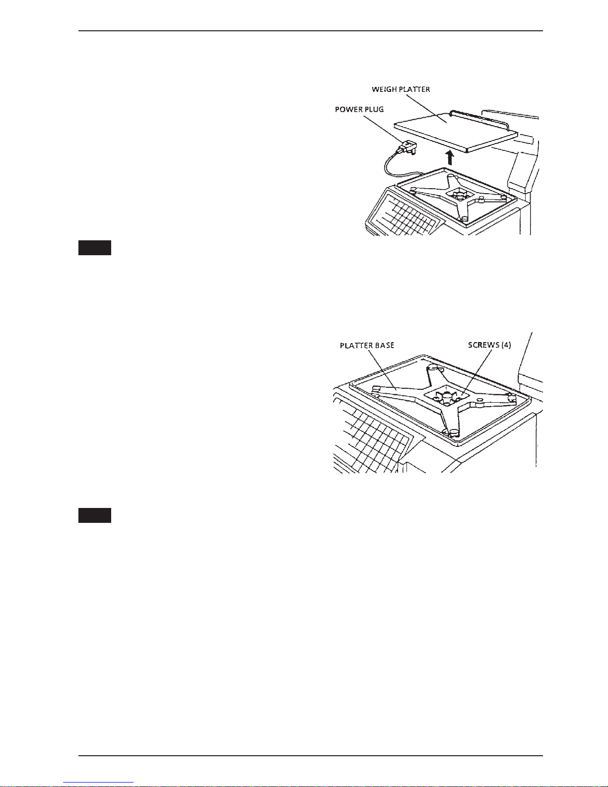
3.2 UPPER COVER REMOVAL
1. Remove the weigh platter.
1) Place the scale on a level surface.
Rotate the adjustment feet to level the scale if
necessary.
2) Unplug the power plug from its outlet.
3) Lift off the weigh platter, keeping it horizontal.
Chapter 3. Parts Disassembly & Replacement
Note:
2. Remove the platter base.
Note:
When replacing the weigh platter, align the platter pins with the rubber inserts on the platter base.
Remove the four attachment screws, then lift off the
platter base.
After replacing the platter base, perform four corner adjustment (Refer to Section 5.5).
BC-3000
• Service Manual • Rev. 1 3 - 3
Chapter 3. Parts Disassembly & Replacement
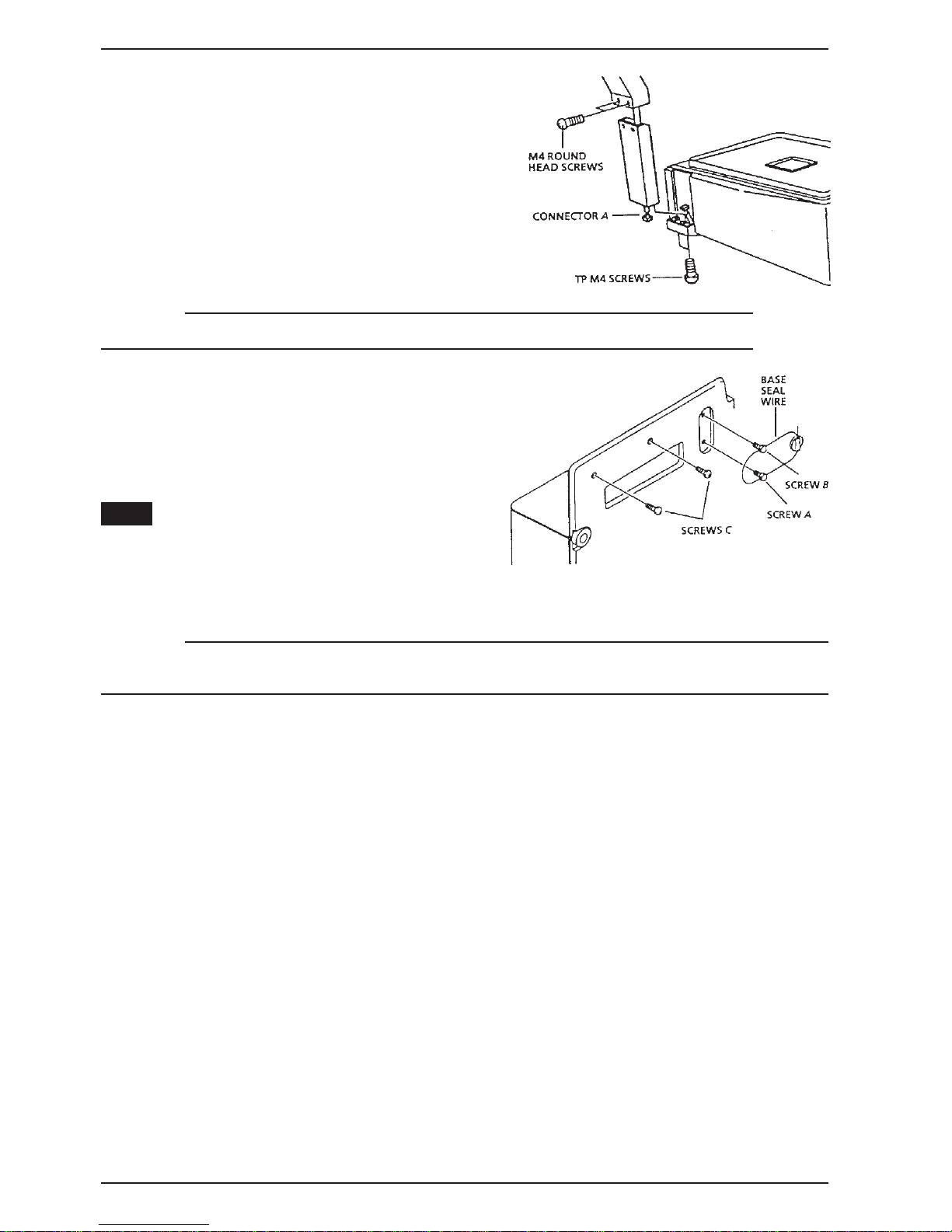
3. Remove display unit.
1) Remove the two screws (M4) that secure the
display pole to the main body.
2) Carefully lift up the display unit and disconnect
connector A.
3) Remove the two screws (M4) which secure the
plastic display housing to the display pole.
CAUTION!
In order to avoid damage to fragile components, be careful not to drop or strongly impact them.
4. Remove the operation keyboard panel.
1) Cut the base seal wire.
2) Remove base seal wire screw B.
3) Remove both screws C.
Note:
The base seal wire is only used for countries
requiring a base seal. For other specifications, remove
only screws B & C.
CAUTION!
After the base seal wire is cut, it is necessary to have the scale re-inspected and the seal replaced. Nev er cut
the base seal unless required.
3 - 4
BC-3000
• Service Manual • Rev. 1

Chapter 3. Parts Disassembly & Replacement
5. Remove the upper case.
1) Lower the side panel in the direction of the
arrow.
2) Cut the seal wire, and remove the seal wire
screws.
3) Remove the four screws which secure the
upper case, then carefully lift the cover off
the main body.
CAUTION!
After the base seal wire has been cut, it is necessary to have the scale re-inspected and the seal replaced.
Never cut the base seal unless required.
BC-3000
• Service Manual • Rev. 1 3 - 5
Chapter 3. Parts Disassembly & Replacement
3.3 CIRCUIT BOARD REPLACEMENT
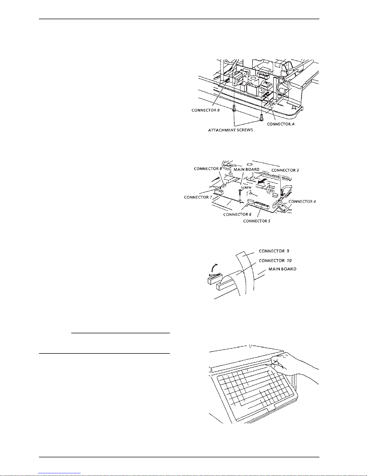
1. Remove the power unit.
1) Remove the two attachment screws from
the power unit located in the lower part of
the scale.
2) Remove connectors A & B.
2. Remove the main board.
1) Remove the attachment screw from the
main board.
2) Slide the main board toward you, and
remove connectors 3~8.
3. Remove the keyboard.
1) Remove connectors 9 and 10 located on
the main board beside the keyboard.
2) Peel off the keyboard starting from the
corner.
CAUTION!
If the keyboard is removed even once, it becomes
unusable. Never remove unless necessary.
4. Remove the A/D board.
Remove the A/D board referring to the
procedures described in Load Cell
Replacement section of this manual (Section
3.5).
3 - 6
BC-3000
• Service Manual • Rev. 1

3.4 DISPLAY UNIT REPLACEMENT
Replace display unit.
1) Carefully remove the cover.
2) Remove the four screws which secure the
display unit.
CAUTION!
•
To avoid damage to the cover, open it slowly and carefully.
•
Avoid touching the display unit.
Chapter 3. Parts Disassembly & Replacement
BC-3000
• Service Manual • Rev. 1 3 - 7
Chapter 3. Parts Disassembly & Replacement
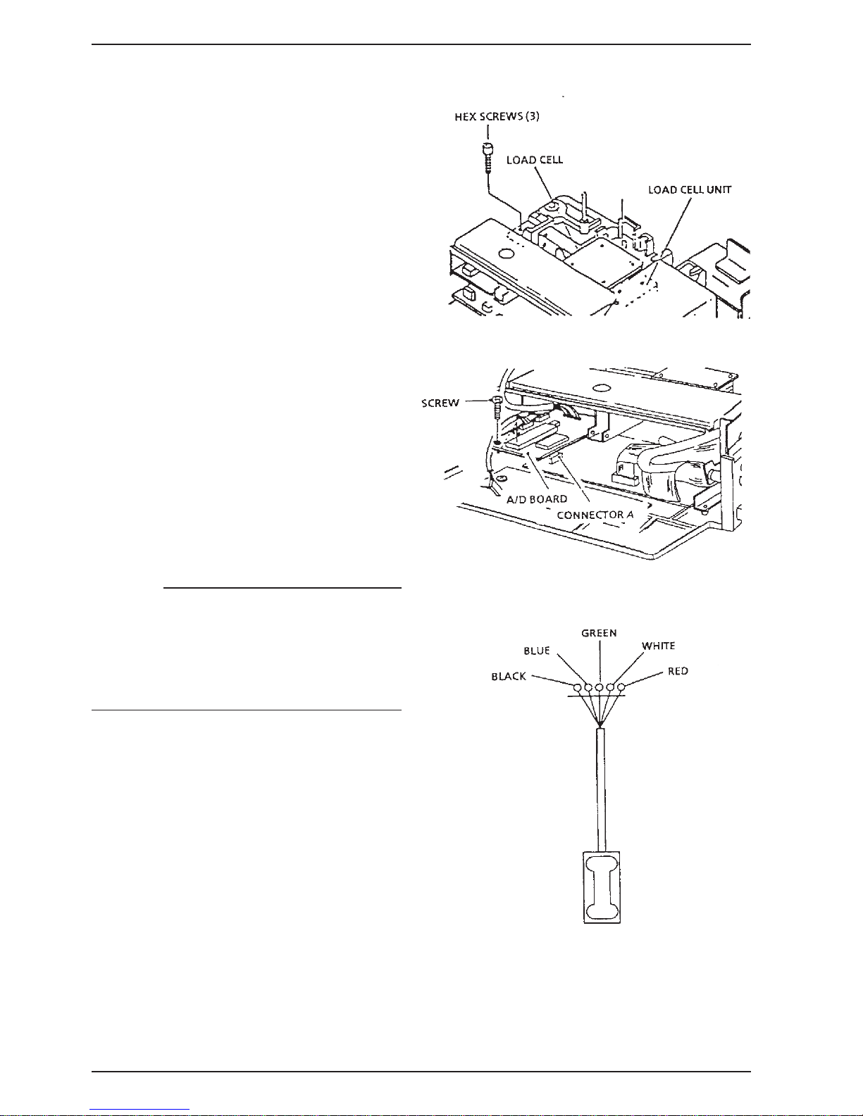
3.5 LOAD CELL REPLACEMENT
1. Remove the upper cover.
Refer to Section 3.2 of this manual for upper
cover removal procedure.
2. Remove the load cell unit.
1) Remove the three screws which secure
the load cell unit.
2) Remove the load cell unit.
3. Remove the A/D board.
1) Remove the screw which secures the A/D
board.
2) Slide the A/D board from its plastic bracket
and disconnect Connector A.
3) Remove the load cell output cable
(soldered in five places).
CAUTION!
•
The load cell output cable has five soldered
points. When replacing be sure that the wires
are in the correct order.
•
After replacing the load cell unit, perform a fourcorner test. (Reference: Section 5.5 of this
manual)
3 - 8
BC-3000
• Service Manual • Rev. 1
4 ELECTRONIC CONFIGURA TIONS
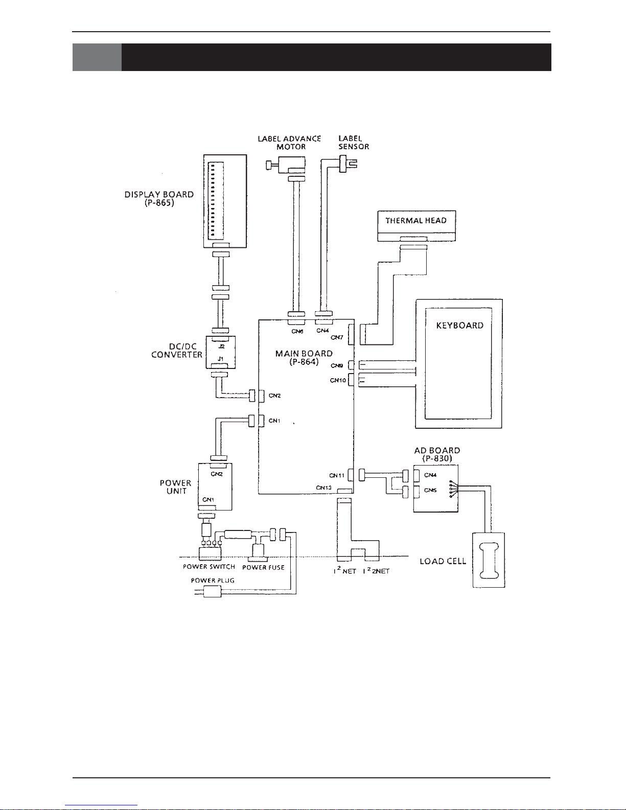
4.1 CONNECTOR CONFIGURATION
Chapter 4. Electronic Configurations
BC-3000
• Service Manual • Rev. 1 4 - 1
Chapter 4. Electronic Configurations
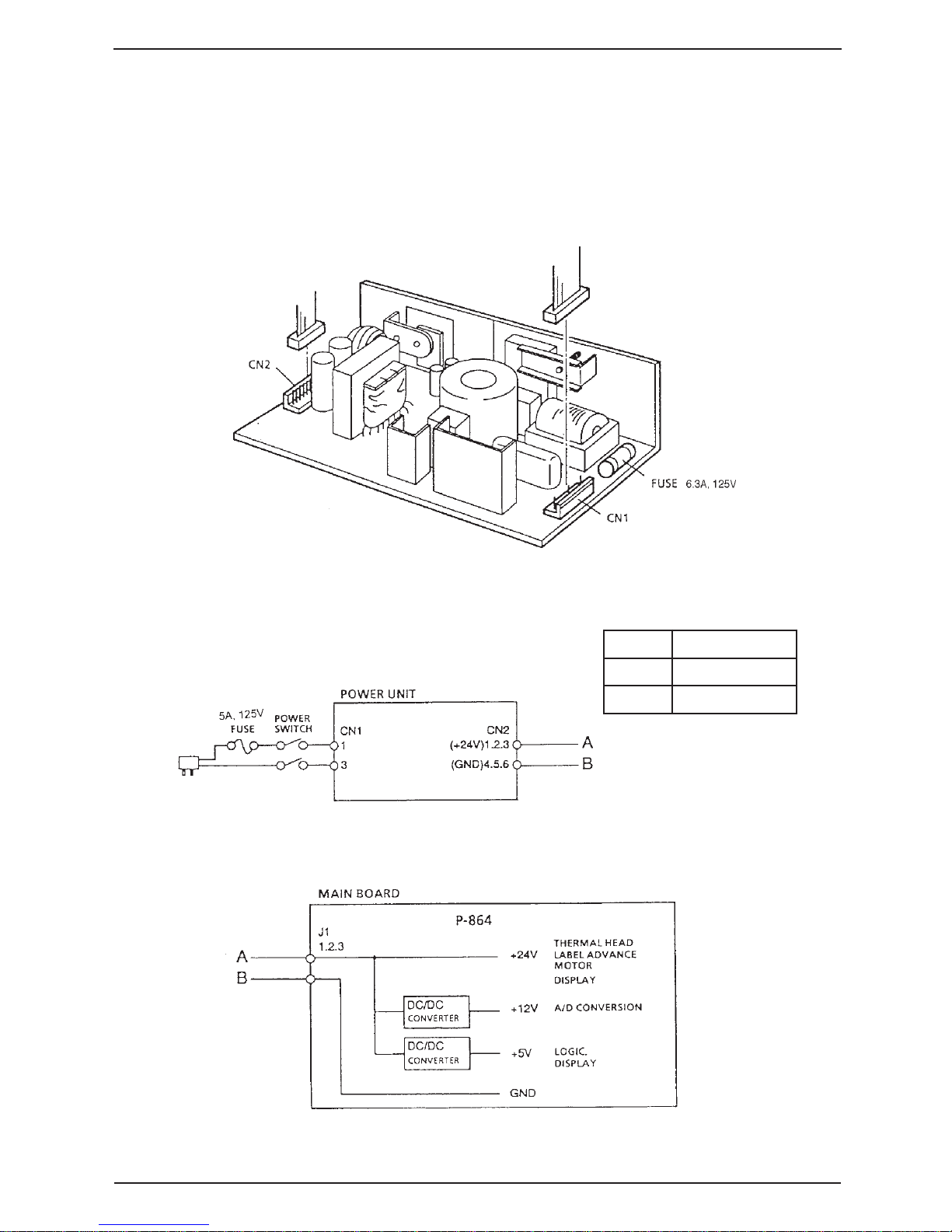
4.2 POWER UNIT
The power unit performs efficient voltage conversion, stabilizes low voltage, and supplies power to the
various units.
External View
Block Diagram
1NCP001SLS
1V511ot001CA
3V511ot001CA
4 - 2
BC-3000
• Service Manual • Rev. 1
Chapter 4. Electronic Configurations
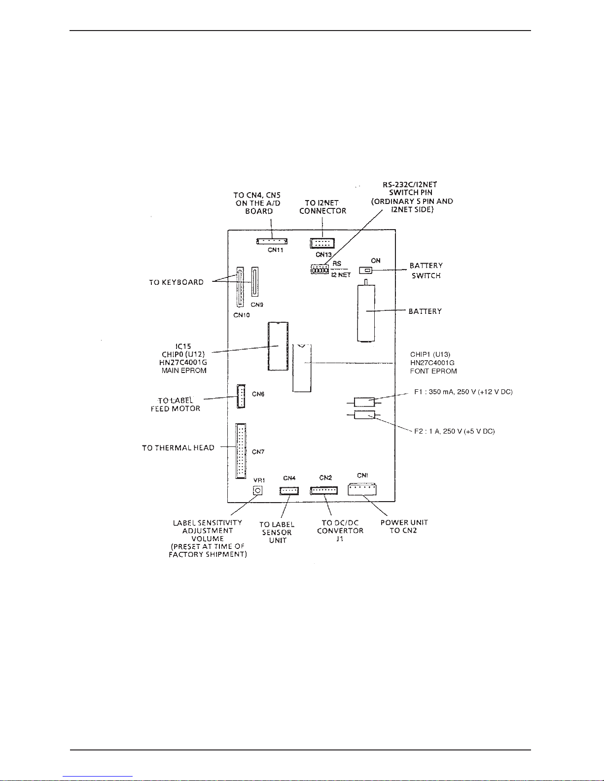
4.3 MAIN BOARD (P-864)
This board is equipped with a 16-bit microprocessor and is used to process scale data. The board is multilayered, and its high precision construction is designed to reduce electrical impedance, electrical noise, and
static electricity.
External View
BC-3000
• Service Manual • Rev. 1 4 - 3
Chapter 4. Electronic Configurations
Board Functions
• Control of overall unit via CPU (V40)
*EPROM (Program memory) 4 Meg type (2) are installed
• Process weight data from A/D board
• Key data input
• Price calculation
• Display of weight, price and unit price data
• Label advance motor output
• Thermal head printing output
2
• I
NET output
• Label sensor input
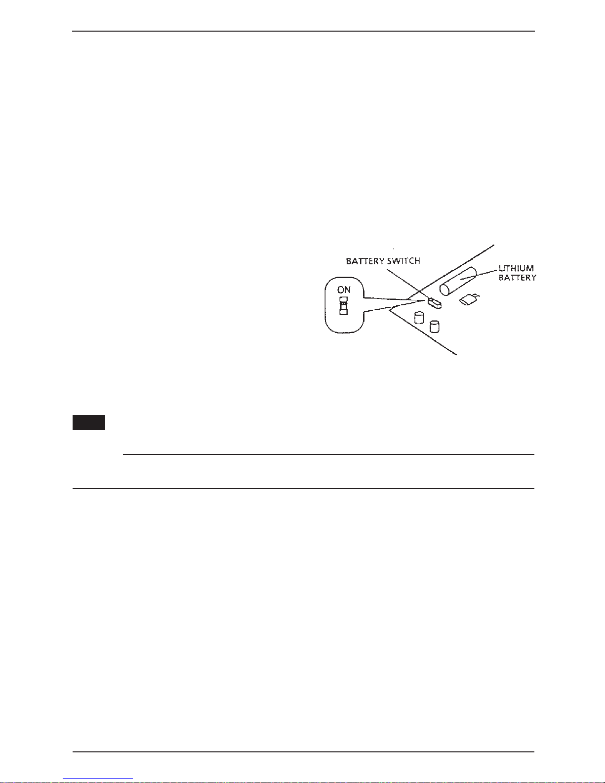
Battery Switch
A lithium memory backup battery is included
in these units.
After installation, make sure the battery switch
is set to ON.
Note:
This scale uses a rechargeable lithium battery . Normal charge is 3.6V . Battery switch is set to ON at
time of shipment from factory.
CAUTION!
There is danger of explosion if this battery is incorrectly replaced. Replace only with the same or equivalent
type recommended by the manufacturer . Discard used batteries according to the manufacturer's instructions .
4 - 4
BC-3000
• Service Manual • Rev. 1
Chapter 4. Electronic Configurations
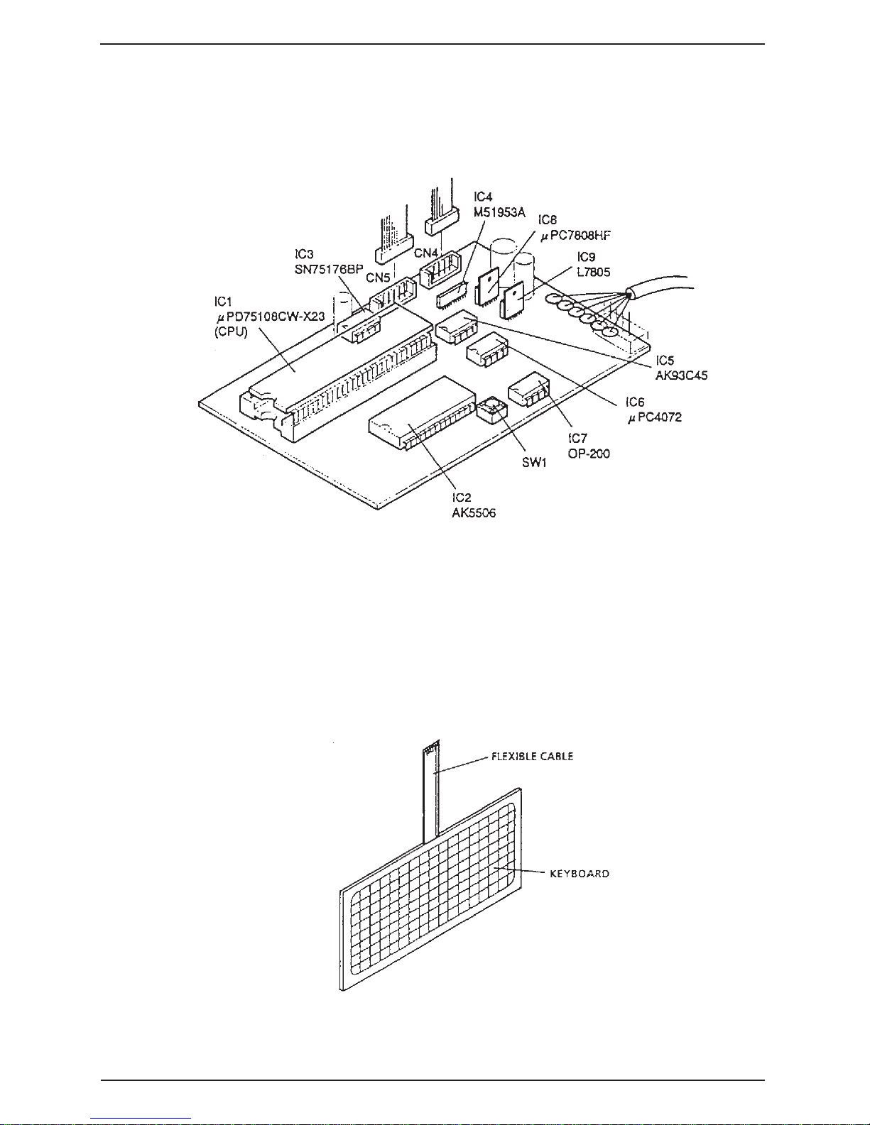
4.4 A/D BOARD (P-830)
The A/D board converts analog weight data from the load cell into digital data, and performs automatic span
control and zero compensation.
External View
4.5 KEYBOARD
This is a panel type keyboard.
A flexible cable connects it to the main keyboard (CN9 and CN10).
External View
BC-3000
• Service Manual • Rev. 1 4 - 5
Chapter 4. Electronic Configurations
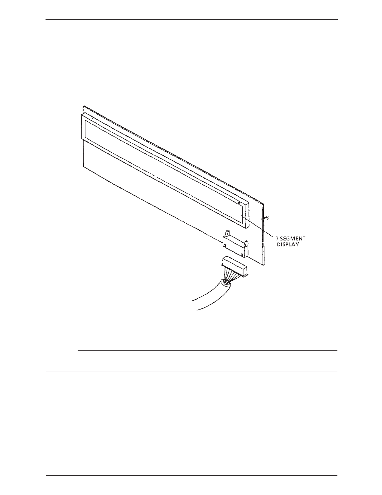
4.6 DISPLAY UNIT (P-856)
• The BC-3000 is equipped with a 7-segment display module.
• Weight, price, and unit price data are displayed.
External View
CAUTION!
•
The display modules are made of glass so care should be taken not to touch or impact the units.
•
Do not remove the connectors with the power ON.
4 - 6
BC-3000
• Service Manual • Rev. 1
4.7 DC/DC CONVERTER
The DC/DC converter transfers the voltage supplied to the display board.
External View
Chapter 4. Electronic Configurations
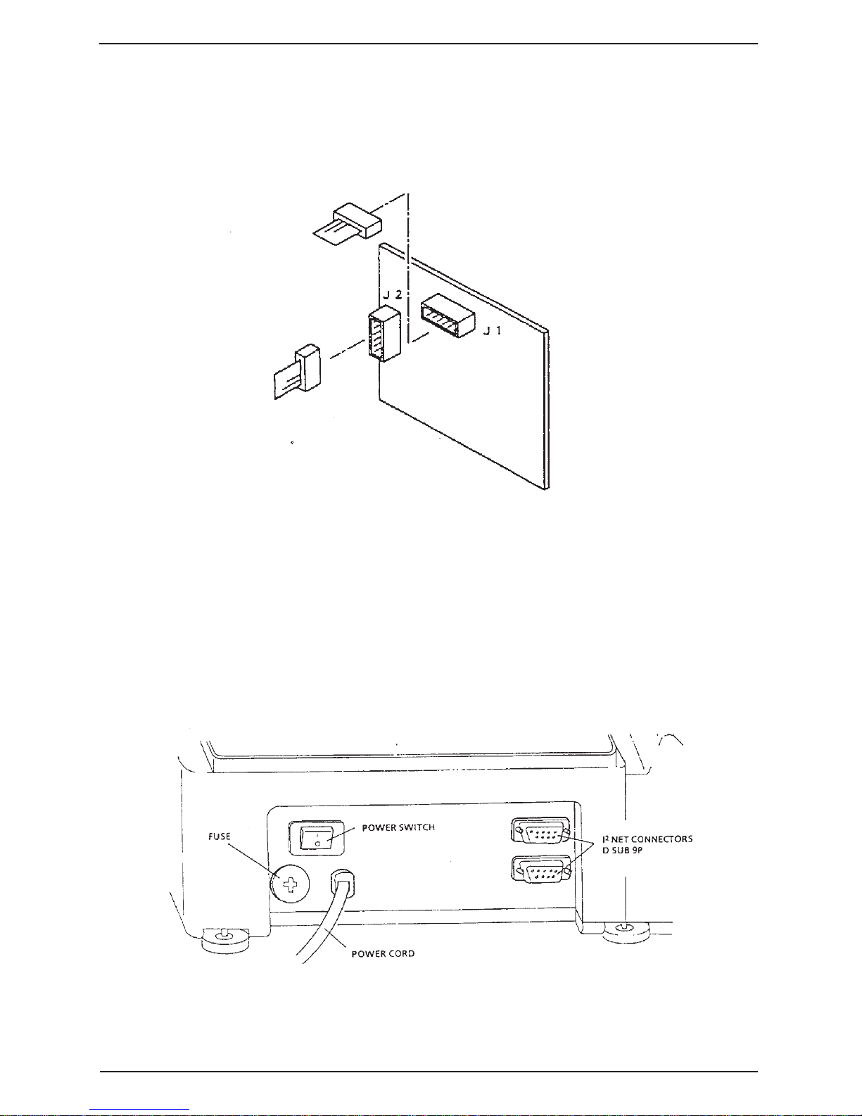
4.8 CONNECTOR BRACKET
Includes the power switch, power cord, fuse, and I2NET connectors.
External View
BC-3000
• Service Manual • Rev. 1 4 - 7
Chapter 4. Electronic Configurations
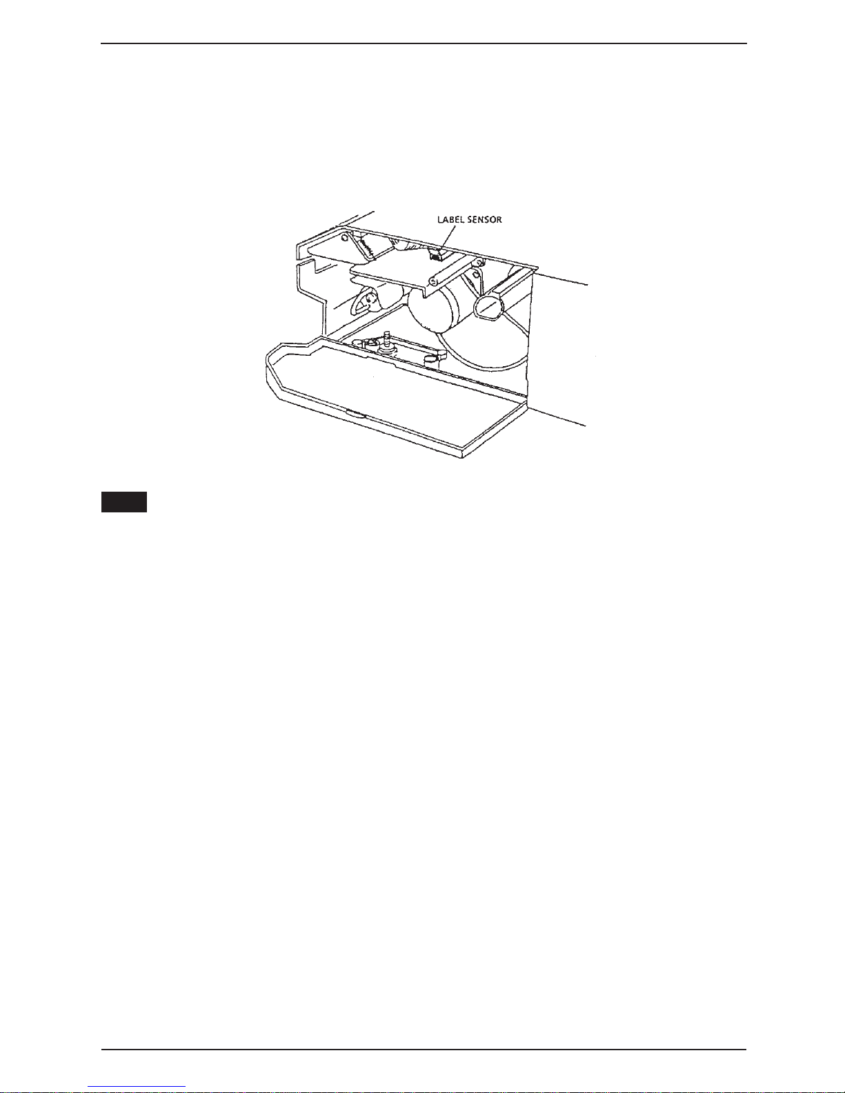
4.9 LABEL SENSOR
The label sensor utilizes a photo-interrupter to detect the gap between labels, and functions to ensure that
labels are printed correctly one at a time.
External View
Note:
See Section 5.5 for adjustment procedures.
4 - 8
BC-3000
• Service Manual • Rev. 1
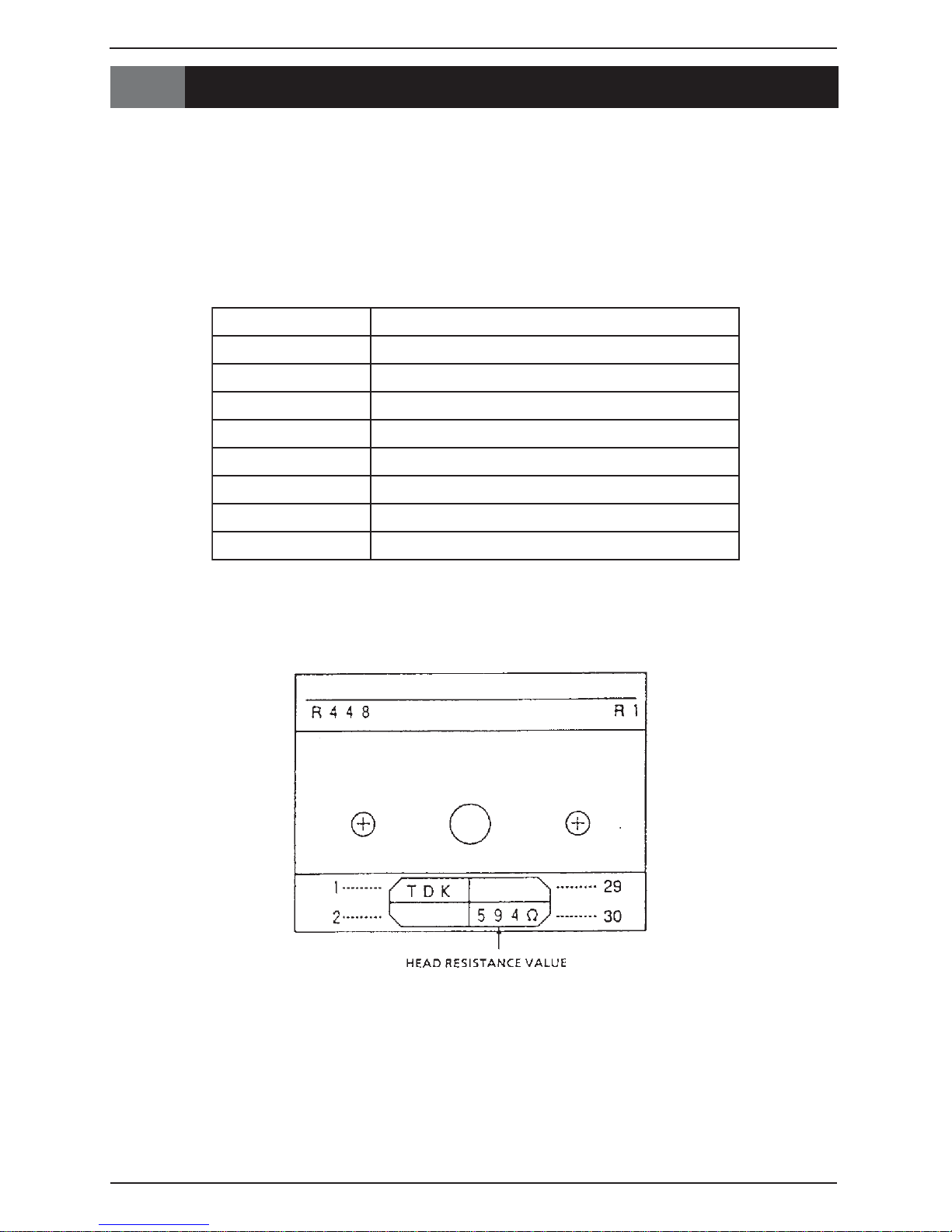
5 THERMAL HEAD
5.1 OVERVIEW
This 448 dot thermal head is specifically intended for use with label printers.
5.2 SPECIFICATIONS
Specification Sheet
epyTKDT)daehlamrehtytisnedelbuoD(I4213HL
tnuoctodllarevOstod844
hctiptoD)H(mm51.0x)W(531.0
ecnatsiserdaeH276ot825=R Ω
rewopderiuqeRtod/W88.0
egatlovdeilppAV42
Chapter 5. Thermal Head
Configuration
htdiwtnirpmumixaMmm5.06
noituloseR)mm/stod4.7(hcni/stod881
deepstnirP)ces/mm07(ces/hcni8.2
BC-3000
• Service Manual • Rev. 1 5 - 1
 Loading...