

Page 1
ISHIDA SCALES MFG.CO., LTD.
44
SANNO-CHO SHOGOIN SAKYO-KU KYOTO
606
JAPAN
REVISION
0
Page 2

You can help improve this manual by calling attention to errors and recommending improvements. Please convey your comments to the
nearest Ish ida Scales regional representative.
Thank
You!
Copyright0
1991
by
lshida Scales
Mf
.
Co., Ltd.
All
Rights Reserved.
No part of this manual may be repro
d
uced in any form, by mimeograph or any
other means, without permission in writing from the publisher.
Page 3
TABLE OF CONTENTS
H1 INTRODUCTION
1.1 External Views
1.2 Dimensions
1.3 Features
1.5 Key Switch and Reset Key
H2 MECHANICAL CONFIGURATION
2.1 Mechani'cal Components
2.2
Internal Components
H3 REPLACEMENT PROCEDURE
3.1 Outer Case Removal
3.2 Load Cell Replacement
3.3 Electrical Component Replacement
3.4 Display Panel Replacement
3.5 Cassette
'>d
H4 ELECTRICAL CONFIGURATION
Block Diagram
Connector Diagram
Power Unit
A/D Board (P704)
Main Board (P750)
Rom/Ram Board
(
P7
51
)
Battery Switch Check
Sensor Signal Relay Board (P755)
Display Unit
Peeling Sensor
Label Sensor
Cassette Sensor
B5
THERMAL
IIEAD
5.1 Outline
5.2 Specifications
5.3 Configuration
5.4 Adjustments
I16 ADJUSTMENTS
6.1 Overview
6.2 Adjustment Items
6.3 Four-Corner Limit Adjustments
6.4 Initial A/D Value Adjustment
6.5 Span Adjustment
6.6 Ad jus tlnent Sequence
6.7 Peeling Sensor Adjustment
H7 INSTALLAT'ION
7.1 Procedure For Installation
Page 4
MA1N1.L'ENANCJ<
8.1 Outline
8.2 When Replacing
A
Defective Unit
8.3
Cleaning
8.4 Daily Inspection
8.5 Preventive Maintenance
8.6 Troubleshooting
PARTS
9.1 Ovcrvicw
9.2 Parts List
OUTLINE OF SOPTWRRE
1.1 Memory
1.2 PLU File
1.3 Label Formatting
1.4
Non-Keyboard Characters
LABEL
F0KMATTING:USA
TOTALS
SET
UP
MODE
TEST MODE
Page 5
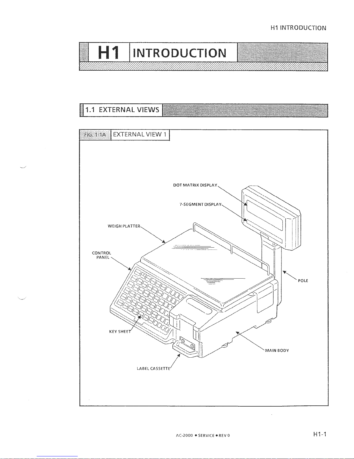
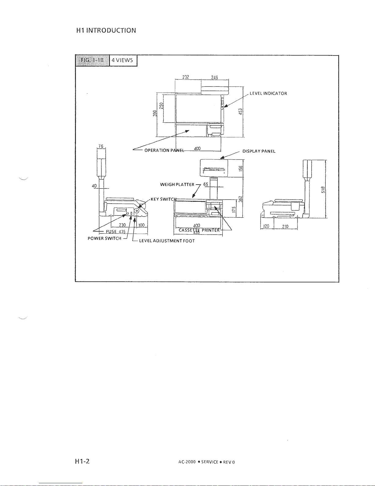
HI
INTRODUCTION
FIG.
1-1.4
EXTERNAL
VIEW
1
AC-2000 SERVICE REV 0
Page 6
HI INTRODUCTION
LEVEL INDICATOR
DISPLAY PANEL
WEIGH PLATTE
P
AC-2000 SERVICE 0 REV 0
Page 7
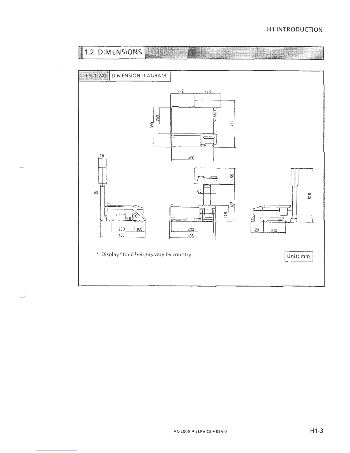
H1
INTRODUCTION
*
Display Stand heights vary by country
FIG,
t*2A
AC-2000
SERVICE REV
0
DIMENSION DIAGRAM
Page 8
HI
INTRODUCTION
The
AC-2000
includes the following features:
Two
16
bit microprocessors
(V-40)
to process weight data
Dot matrix display
)
FIP256X64AB Flourescent Display Panel, 256x64 dot
)
Commercial message display capability
E2
Prom (EP-ROM)
)
Electronically readlwritelerase ROM
)
Essential data initial setting
)
Data is maintained even when power is cut
Lithium battery
)
Lithium battery for memory backup power. No need to recharge the battery upon installation (battery has'sufficient reserve that the battery
switch
is
set to
ON
at time of factory shipment).
CAUTION: Danger of explosion if battery
is
incorrectly replaced. Replace only with the same or equivalent type recommended by the manufacturer. Discard used batteries according to the manufacturer's
instructions.
12
NET (INC
003
used for data transmission. lshida transmission specs)
Label Cassette for easy changeover and reduced storage space
Simplified adjustment of thermal head voltage via software parameters
)
Thermal head resistance value can be entered via key panel. Voltage can
be set to desired value.
Monitoring of peeling sensor
)
Standard peeling sensor detection voltage level is displayed
)
No need to measure voltage using a meter
Selling mode can be set to user's specifications.
e
System expansion
For further information on features please refer to the Operation Manual.
AC-2000
SERVICE REV
0
Page 9
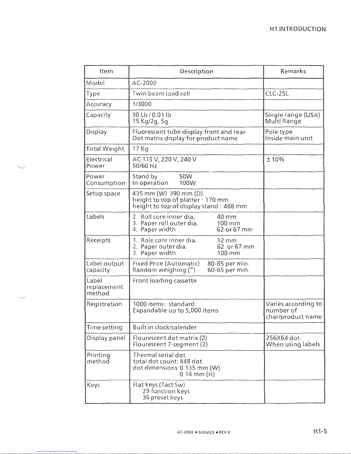
HI INTRODUCTION
Item
Model
Description Remarks
Twin beam load cell
Accuracy
Capacity jingle range (USA)
Vlulti Range
Display Fluorescent tube display front and rear
Dot matrix display,for product name
I7 Kg
'ole type
nside main unit..
Total Weight
Electrical
Power
Power
Consumption
AC 1 15
V,
220
V,
240
V
50160
Hz
Stand by 50W
In operation 100W
Setup space 435 mm (W) 390 mm
(D)
height to top of platter : 170 mm
height to top of display stand
:
468 mm
Labels
2. Roll core inner dia,
40 mm
3.
Paper roll outer dia. 100 mm
4. Paper width
62 or 67 mm
Receipts
1. Role core inner dia. 12 mm
2.
Paper outer dia. 62 or 67 mm
3.
Paper width 100 mm
Label output
capacity
Fixed Price (Automatic)
80-85 per min.
Random weighing
(")
60-65 per min.
Label
replacement
method
Registration
Front loading cassette
1000 items: standard
Expandable up to 5,000 items
Varies according to
number of
charlproduct name
Time setting
Display panel
Built in clocklcalender
Flourescent dot matrix
(2)
Flourescent 7-segment (2)
256x64 dot
When using labels
Printing
method
Thermal serial dot
total dot count: 448 dot
dot dimensions 0.1 35 mm (W)
0.14 mm
(H)
Keys
Flat keys (Tact Sw)
29 function keys
36 preset keys
AC-2000
SERVICE
REV
0
Page 10
HI
INTRODUCTION
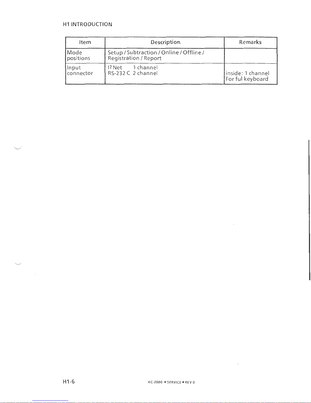
Mode
positions
Input
connector
Description
Setup
/
Subtraction /Online / Offline
/
Registration / Report
12
Net
1
channel
RS-232
C
2
channel
AC-2000 SERVICE REV 0
Remarks
_i
inside: 1 channel
For ful keyboard
Page 11
H1
INTRODUCTION
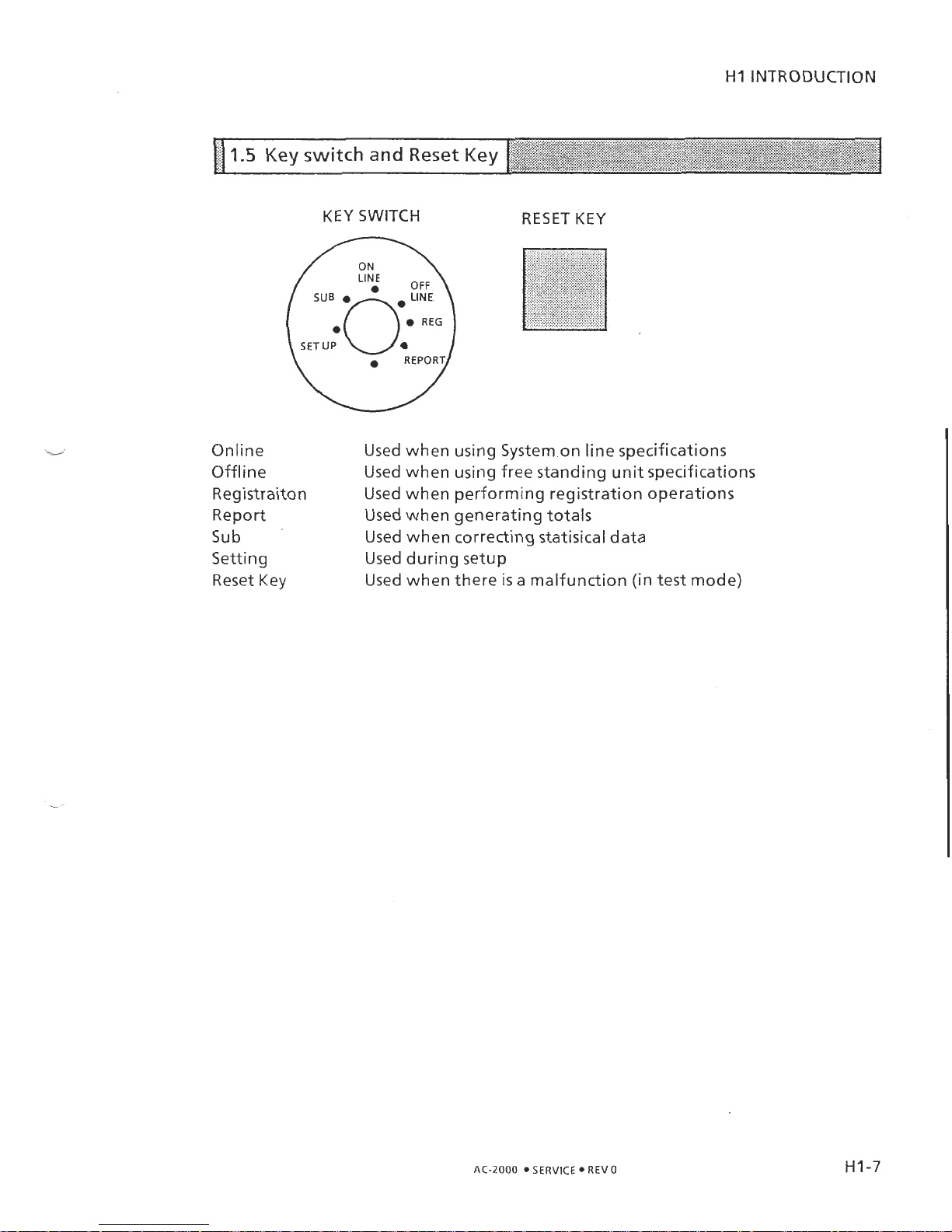
KEY
SWITCH RESET
KEY
Online
Used when using System.on line specifications
Offline Used when using free standing unit specifications
Registraiton Used when performing registration operations
Report Used when generating totals
Sub
Used when correcting statisical data
Setting Used during setup
Reset Key Used when there
is
a malfunction (in
test
mode)
AC-2000
SERVICE
REV
0
Page 12
H2 MECHANICAL CONFIGURATION
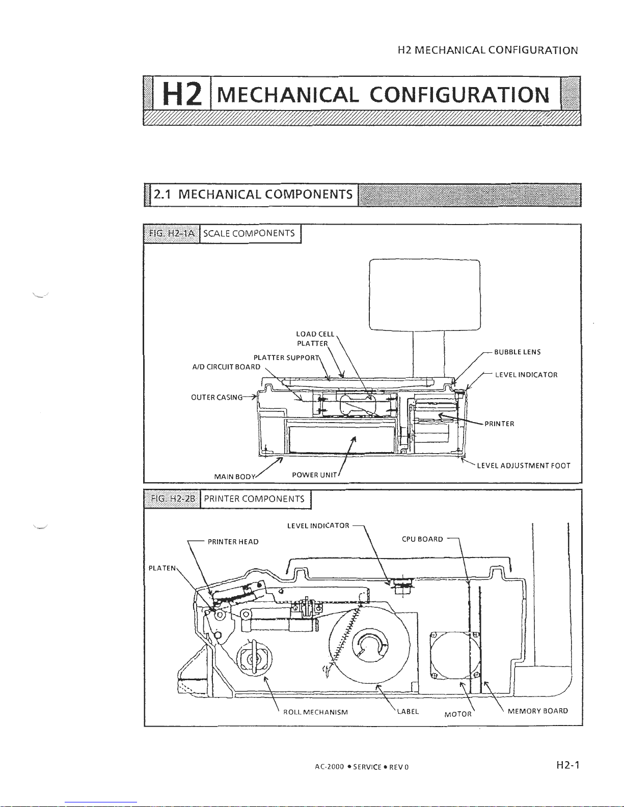
SCALE COMPONENTS
BUBBLE LENS
AID CIRCUIT BOARD
LEVEL INDICATOR
OUTER CASIN
'
ROLL MECHANISM
\
\
MEMORY BOARD
AC-2000
SERVICE REV
0
Page 13
H2 MECHANICAL CONFIGURATION
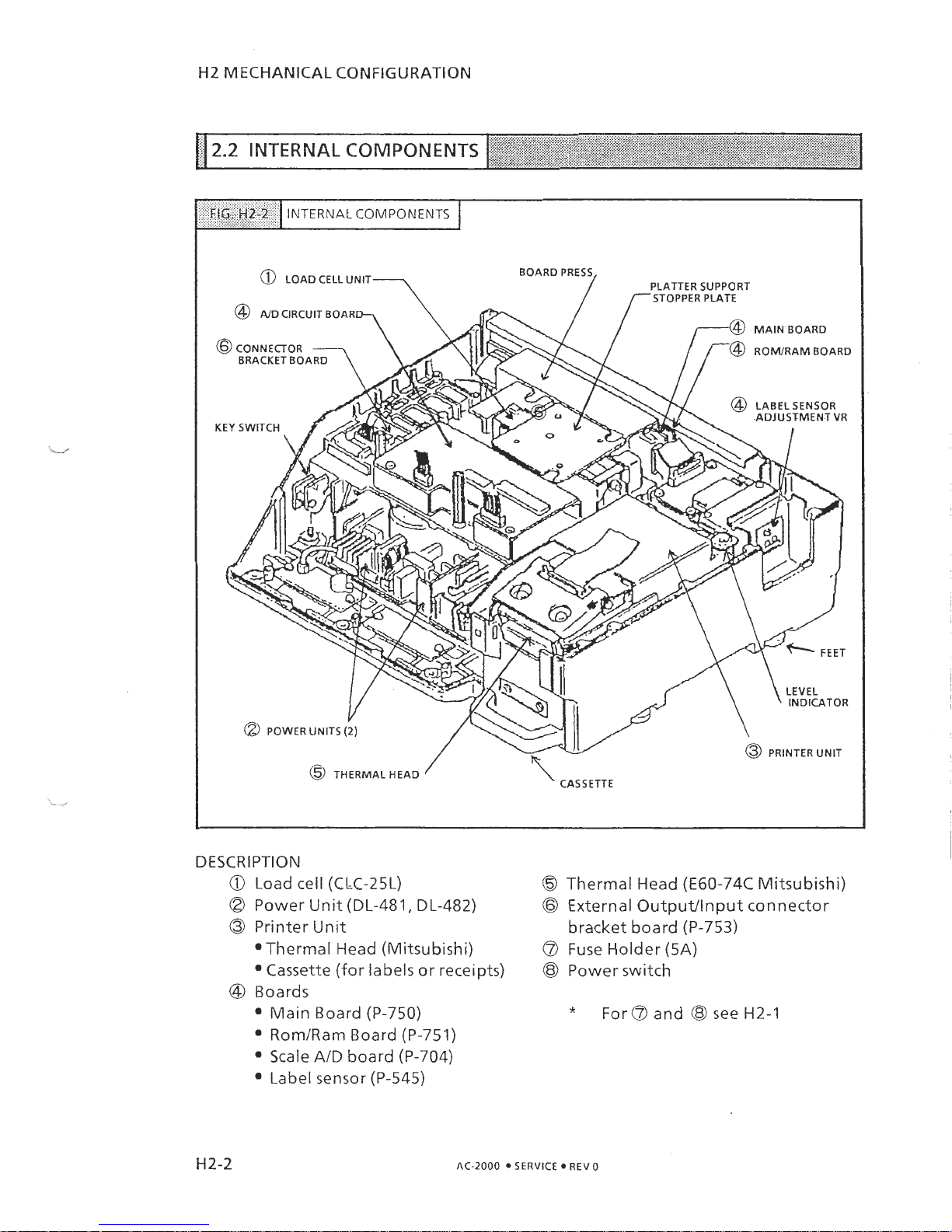
DESCRIPTION
0
Load cell (CLC-25L)
O
Thermal Head (E60-74C Mitsubishi)
Power Unit (DL-481, DL-482)
@
External Output/lnput connector
a
Printer Unit
bracket board (P-753)
@Thermal Head (Mitsubishi)
@
Fuse Holder (5A)
Cassette (for labels or receipts)
@
Power switch
@
Boards
Main Board (P-750)
*
For @ and @ see H2-1
RomIRam Board (P-751)
Scale AID board (P-704)
Label sensor (P-545)
AC-2000
SERVICE
REV
0
Page 14
H3
REPLACEMENT PROCEDURE
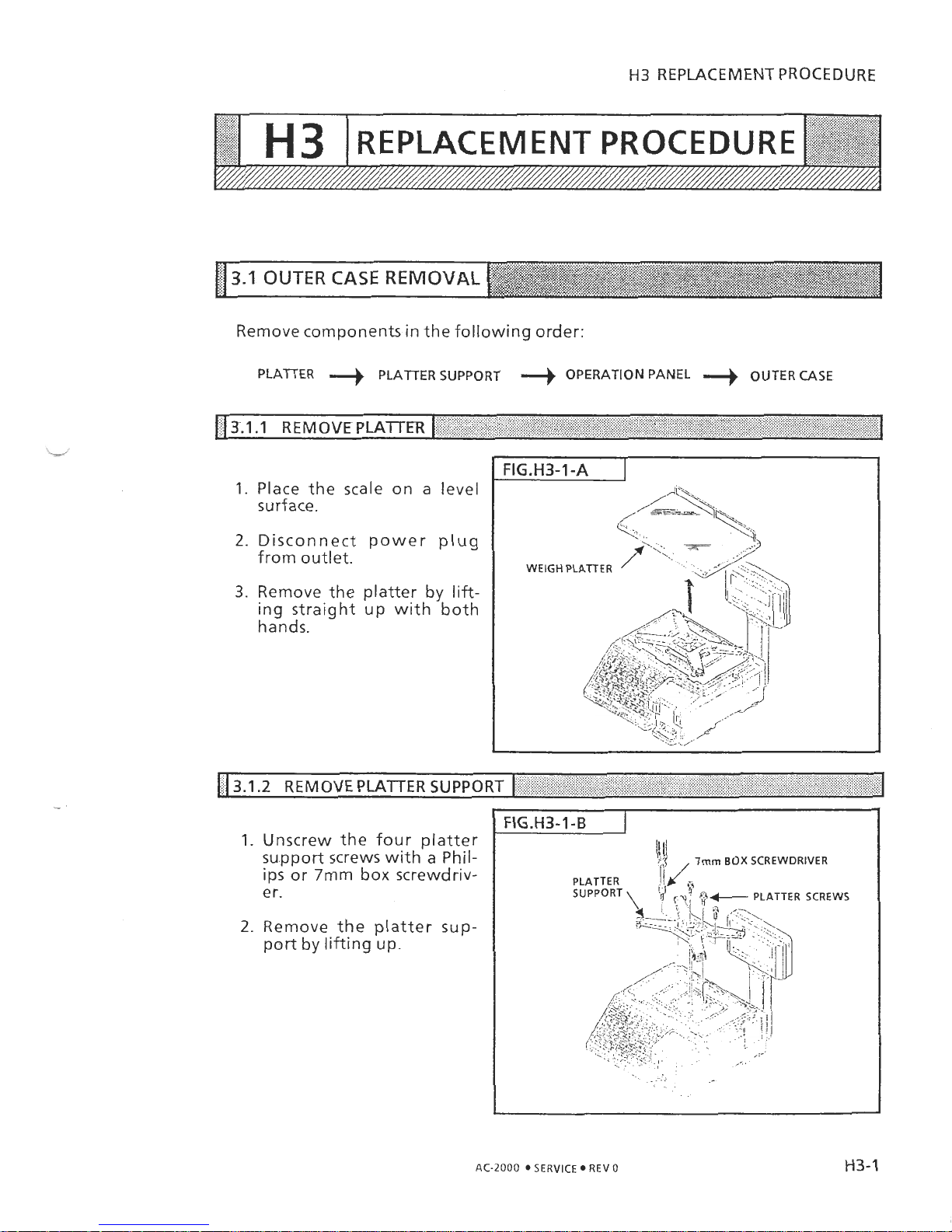
Remove components in the following order:
PLATTER
II)
PLA'ITER SUPPORT
II)
OPERATION PANEL
II)
OUTER CASE
.
,
,
.
,
,
,,,,
\
,
,
,,
..
.
%.,
<
*",
:;'
*,
,
,
[
3.1 1
REMOVE PLAITER
(
,,
1.
Place the scale on a level
surface.
2.
Disconnect power plug
from outlet.
3.
Remove the platter
by
lifting straight up with both
hands.
113.1.2
REMOVE PLATTER SUPPORT
I
,,
+<
I
1.
Unscrew the four platter
su.pport screws with a Philips or
7mm
box screwdriv-
er.
2.
Remove the platter sup-
port by lifting up.
&j
,
lmm
BOX
SCREWDRIVER
AC-2000 SERVICE REV0
H3-1
Page 15
H3
REPLACEMENT PROCEDURE
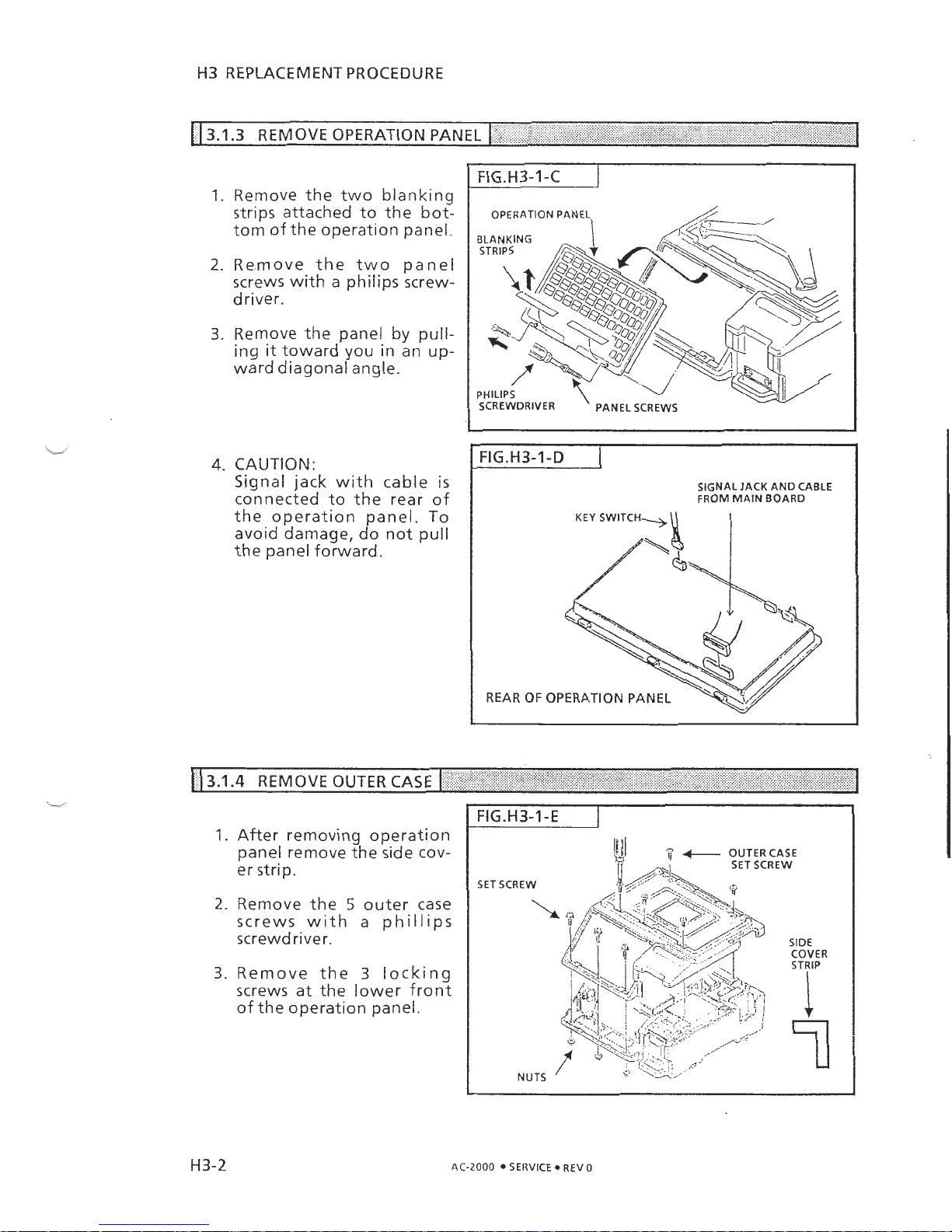
4. CAUTION:
Signal jack with cable
is
connected to the rear of
the operation panel. To
avoid damage, do not pull
the panel forward.
1.
Remove the two blanking
strips attached to the bot-
tom of the operation panel.
2.
Remove the two panel
screws with
a
philips screw-
driver.
3.
Remove the panel
by
pull-
ing it toward you in an up-
ward diagonal angle.
SIGNAL JACK AND CABLE
FROM MAIN BOARD
\
>'
<
13.1.4
REMOVE OUTER CASE
I
I
1.
After removing operation
panel remove the side cover strip.
2.
Remove the 5 outer case
screws with a phillips
screwdriver.
3.
Remove the 3 locking
screws at the lower front
of the operation panel.
SET
Page 16
H3
REPLACEMENT PROCEDURE
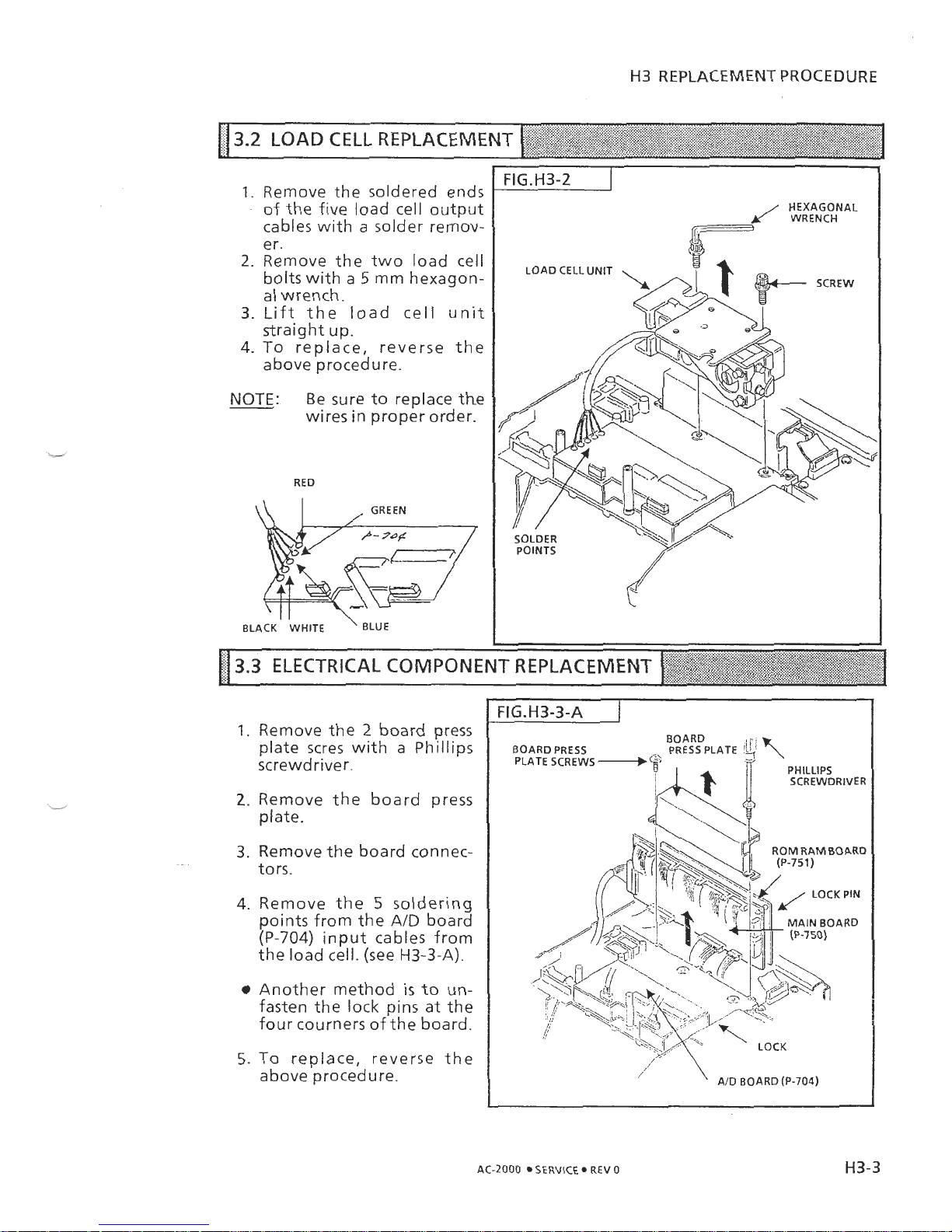
1.
Remove the soldered ends
of the five load cell output
cables with a solder remov-
er.
2.
Remove the two load cell
bolts with
a
5
mm hexagon-
al wrench.
3.
Lift the load cell unit
straight up.
4.
To replace, reverse the
above procedure.
NOTE:
Be sure to replace the
wires in proper order.
RED
.
.
BLACK WHITE ' BLUE
1.
Remove the 2 board press
plate scres with a Phillips
screwdriver.
2.
Remove the board press
plate.
.
-
3.
Remove the board connec-
tors.
4.
Remove the 5 soldering
points from the
AID
board
(P-704)
input cables from
the load cell. (see
H3-3-A).
Another method
is
to
un-
fasten the lock pins at the
four courners of the board.
5.
To replace, reverse the
above procedure.
AC-2000
SERVICE
REV
o
H3-3
Page 17
H3
REPLACEMENT PROCEDURE
n
3.3.2
POWER UNIT REMOVAL(DL-483, DL-482, DL-481)
I
',,
,,
%.
.
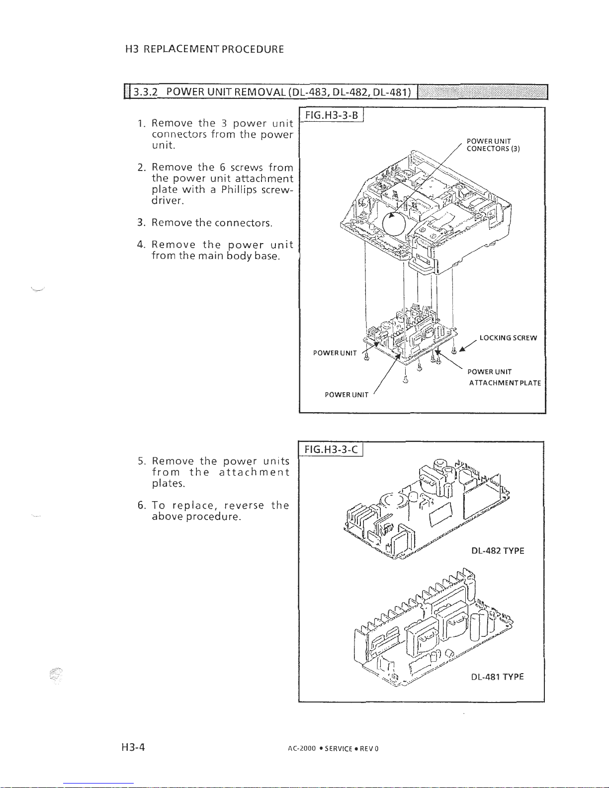
1.
Remove the 3 power unit
connectors from the power-
unit.
2.
Remove the 6 screws from
the power unit attachment
plate with a Phillips screw-
driver.
3.
Remove the connectors.
4.
Remove the power unit
from the main body base.
5.
Remove the power units
from the attachment
plates.
6.
To
replace, reverse the
above procedure.
POWER UNlT
/
CONECTORS
(3)
LOCKING SCREW
POWER UNlT
POWER UNlT
ATTACHMENT PLATE
POWER UNlT
-
-
DL-482
TYPE
DL-481
TYPE
AC-2000
SERVICE REV
0
Page 18
H3
REPLACEMENT PROCEDURE
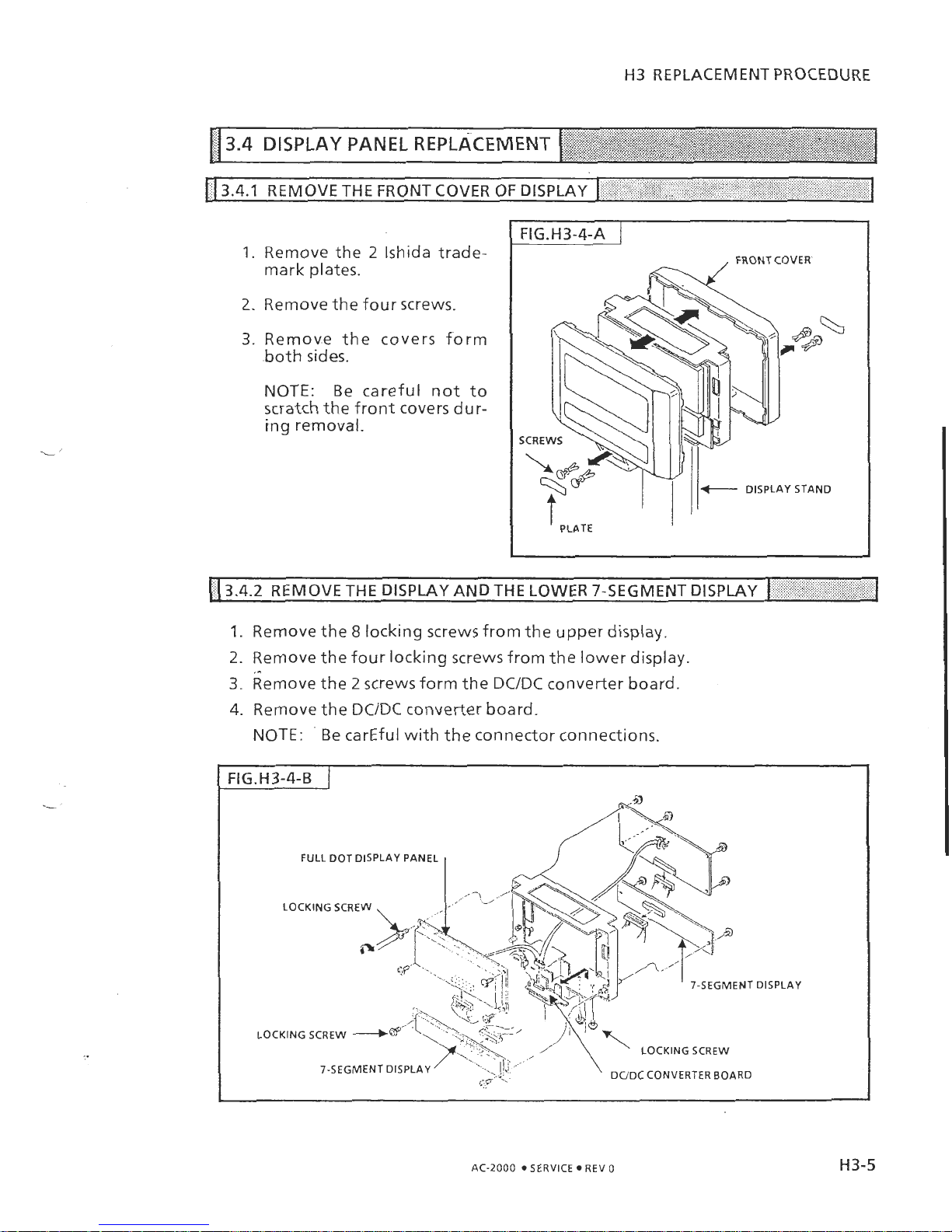
13.4.1
REMOVE THE FRONT COVER OF DISPLAY
I
I
1.
Remove the 2 lshida trademark plates.
2.
Remove the four screws.
3.
Remove the covers form
.both sides.
NOTE: Be careful not to
scratch the front covers dur-
ing removal.
1.
Remove the 8 locking screws from the upper display.
2.
Remove the four locking screws from the lower display.
3.
~emove the 2 screws form the
DC/DC
converter board.
4.
Remove the
DC/DC
converter board.
NOTE:
'
Be carEful with the connector connections.
FULL DOT DISPLAY PANEL
LOCKING SCREW
7-SEGMENT DIS
LOCKING SCREW
7-SEGMENT DISPLAY
&-,a
.
'.
'
DUDC CONVERTER BOARD
PLAY
AC-2000
SERVICE REV
0
Page 19
H3 REPLACEMENT PROCEDURE
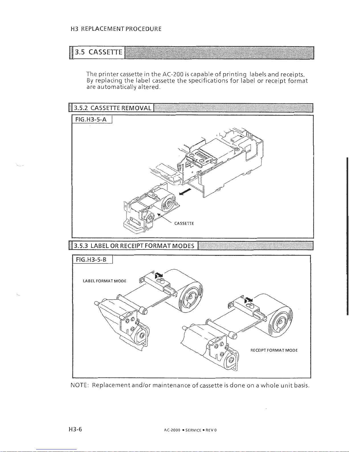
The printer cassette in the
AC-200
is
capable of printing labels and receipts.
By
replacing the label cassette the specifications for label or receipt format
are automatically altered.
NOTE:
Replacement andlor maintenance of cassette is done on
2
whnf~
llnit
ha&
AC-2000
SERVICE REV
0
Page 20
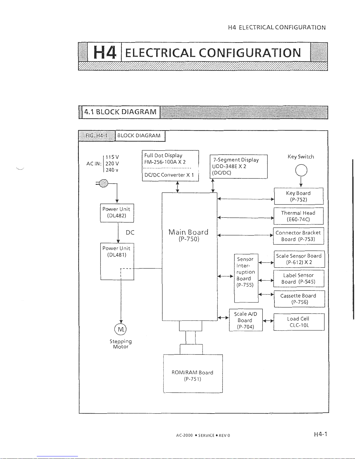
H4
ELECTRICAL CONFIGURATION
Power Unit
(DL482)
(DL481)
FM-256-1
OOA
X
2
..............................
I
DUDC Converter X 1
7-Segment Display
UDD-348E
X
2
(DUDC)
Key Switch
1
?
f
Key Board
b
(P-752)
Stepping
Motor
ROMIRAM
Board
(P-75
1)
Main Board
(P-750)
Connector Bracket
Board (P-753)
Scale Sensor Board
Sensor
Inter-
*
(P-612) X 2
Label Sensor
Board (P-545)
Cassette Board
Scale
AID
Load Cell
-1
Board
hy
(P-704) CLC- 1 OL
AC-2000
SERVICE
REV
0
Page 21

H4
ELECTRICAL
CONFIGURATION
,,,,.
%x
,
,>A,
.,,;,
,,',,
:
4.2
CONNECTOR DIAGRAM
, ,, . ,
I
,
'FiG.ti4-1'5
,A
(CONNECTORDIAGRAM
I
u,
u,
.a
.a
3
AC-2000 SERVICE REV 0
Page 22
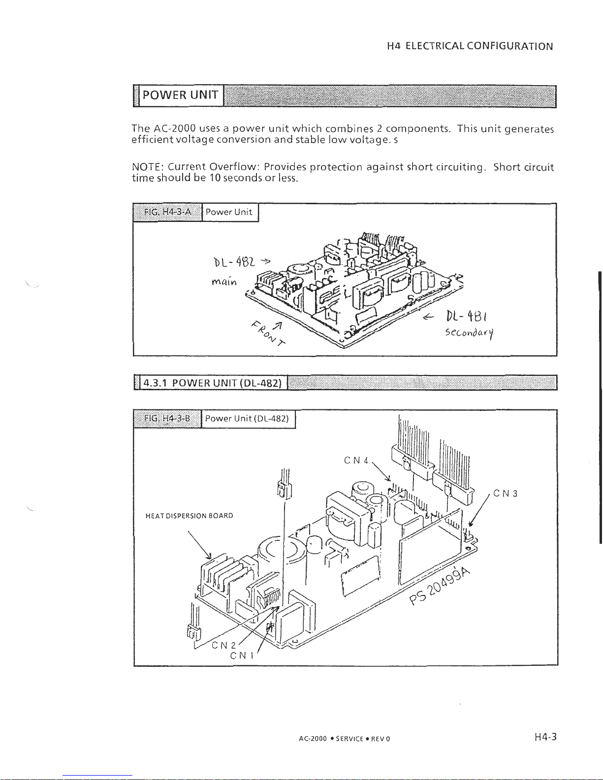
H4
ELECTRICAL CONFIGURATION
The AC-2000 uses
a
power unit which combines 2 components. This unit generates
efficient voltage conversion and stable low voltage.
s
NOTE: Current Overflow: Provides protection against short circuiting. Short circuit
time should be 10 seconds.or less.
1)
4.3.1
POWER UNIT
(DL-482)
(-
1
AC-2000
SERVICE
REV
0
Page 23
H4
ELECTRICAL CONFIGURATION
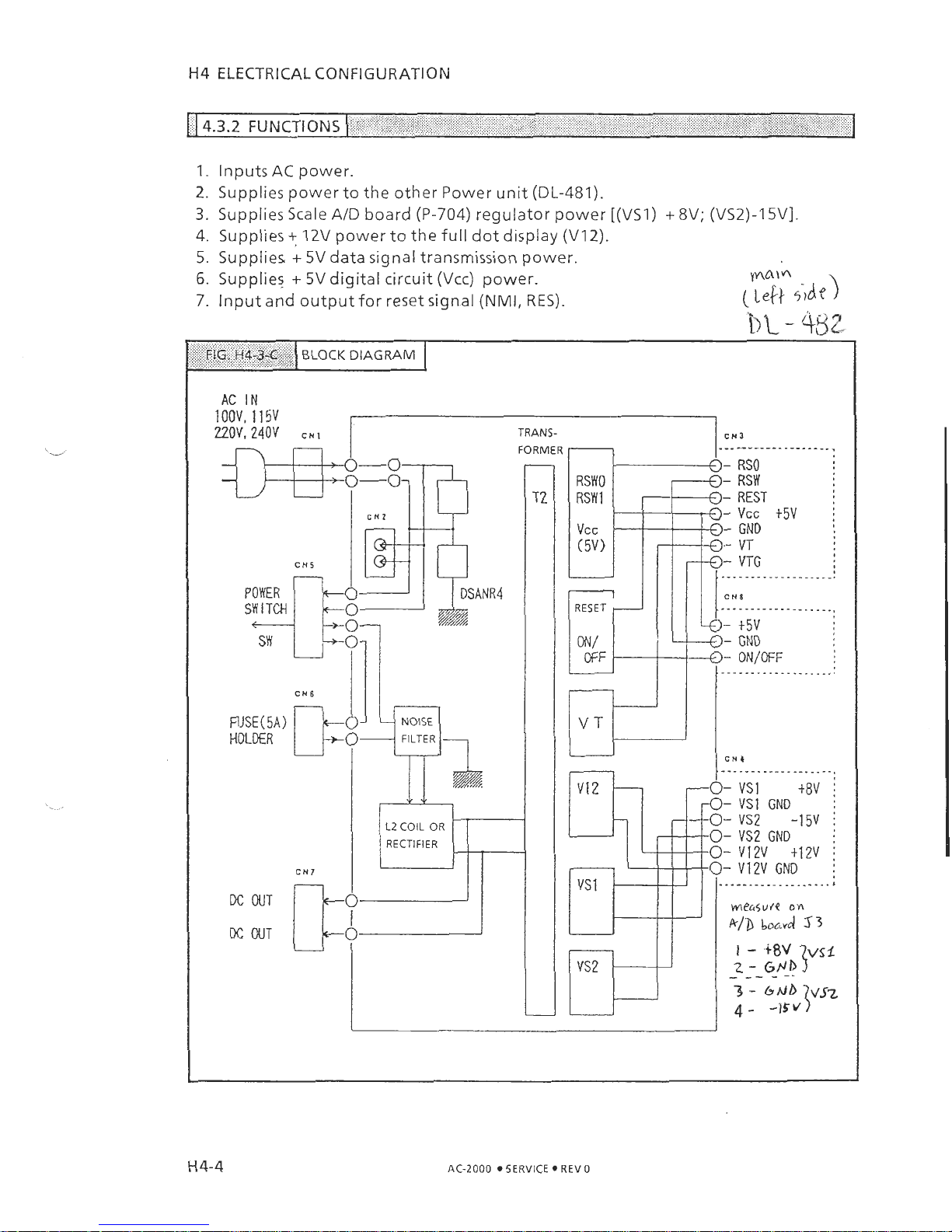
14.3.2
FUNCTIONS
(
,
,
,\%
,
I.
Inputs
AC
power.
2.
Supplies power to the other Power unit (DL-481).
3.
Supplies Scale AID board (P-704) regulator power [(VSI) + 8V; (VS2)-15Vl.
4.
Supplies
+
12V
power to the full dot display
(V12).
5.
Supplies + 5V data signal transmission power.
6.
Supplies + 5Vdigital circuit (Vcc) power.
yv\a\a
7.
Input and output for reset signal
(NMI,
RES).
(~e[/-
side)
1
OOV,
1
1
5v
220V,
240V
CH5
POWER
SW
ITCH
RJSE(5A)
HOLDER
FILTER
-
L2
COIL
OR
RECTIFIER
I
RSWO
1
i
H
4-4
AC-2000
05ERVICE
REV
0
Page 24
H4
ELECTRICAL CONFIGURATION
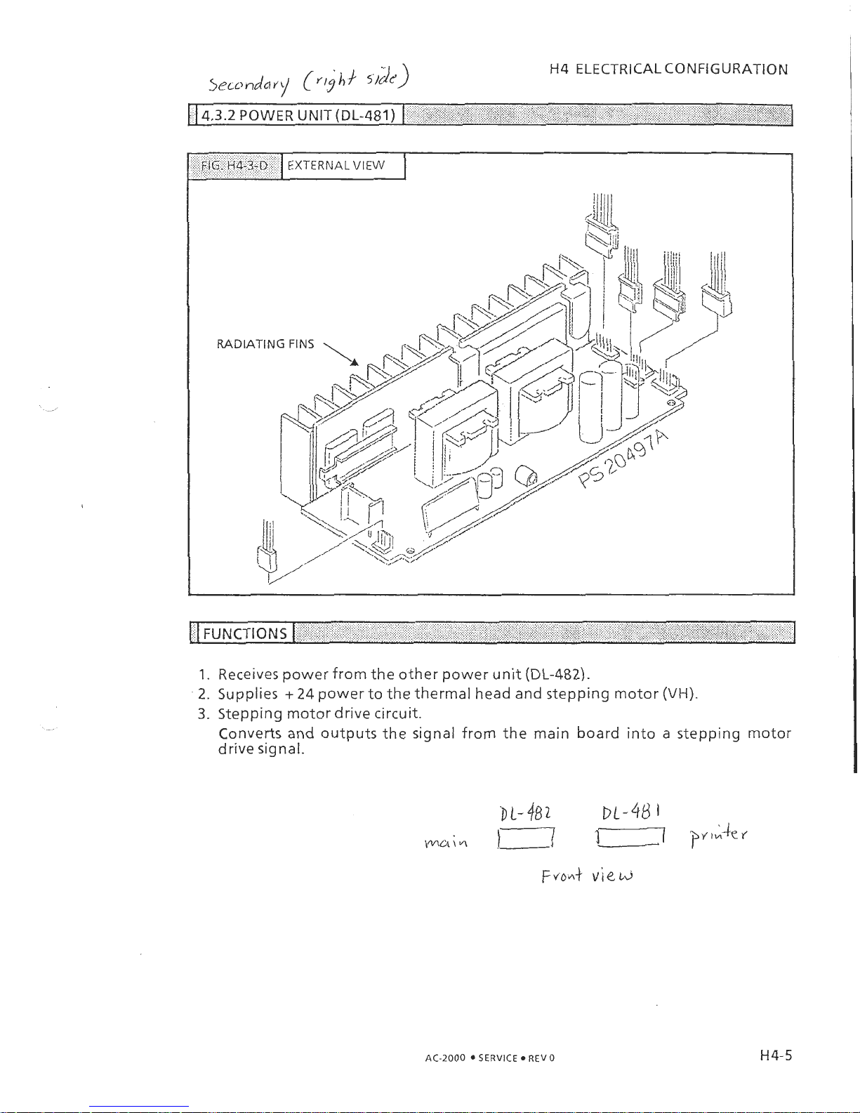
FIG.
H4-3-D
EXTERNAL
VIEW
1.
Receives power from the other power unit (DL-482).
2.
Supplies + 24 power to the thermal head and stepping motor
(VH).
3.
Stepping motor drive circuit.
Converts and outputs the signal from the main board into a stepping motor
drive signal.
AC-2000
SERVICE REV0
Page 25
H4
ELECTRICAL CONFIGURATION
(i.ljhi.
de3
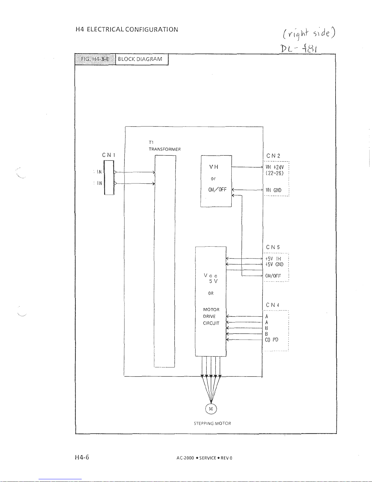
TI
TRANSFORMER
DL--
481
MOTOR
DRIVE
CIRCUIT
FIG.
H4-3-E
VH
GND
i
..............
CN5
BLOCK
DIAGRAM
t5V
IH
i
t5V
GND
i
ON/OFF
i
..............
STEPPING
MOTOR
AC-2000
SERVICE REV 0
Page 26
H4
ELECTRICAL CONFIGURATION
14.3.3
POWER UNIT PERIPHERY
I
,
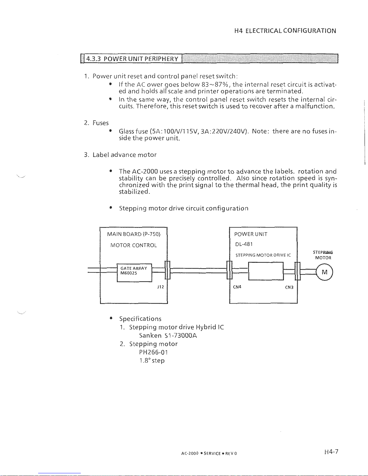
1. Power unit reset and control panel reset switch:
If the
AC
ower goes below
83-87%,
the internal reset circuit is activat-
ed and holds all scale and printer operations are terminated.
In the same way, the control panel reset switch resets the internal circuits. Therefore, this reset switch is used to recover after a malfunction.
2. Fuses
Glass fuse (5A: 100N/115V, 3A:220V/240V). Note: there are no fuse.s in-
side the power unit.
3.
Label advance motor
The AC-2000 uses a stepping motor to advance the labels. rotation and
stability can be precisely controlled.
Also since rotation speed
is
syn-
chronized with the print signal to the thermal head, the print quality
is
stabilized.
Stepping motor drive circuit configuration
Specifications
1. Stepping motor drive Hybrid
IC
San ken 51 -73OOOA
2.
Stepping motor
PH266-01
1.8" step
AC-2000 SERVICE REV
0
.
MAIN BOARD (P-750)
MOTOR CONTROL
--
4
.
GATE ARRAY
M60025
-
_
STEPBLDLG
MOTOR
-,
L
POWER UNIT
DL-48
1
STEPPING MOTOR DRIVE IC
J12
-,
*
-
CN4
CN3
A
-
-
Page 27
H4
ELECTRICAL CONFIGURATION
\,
i
',
11
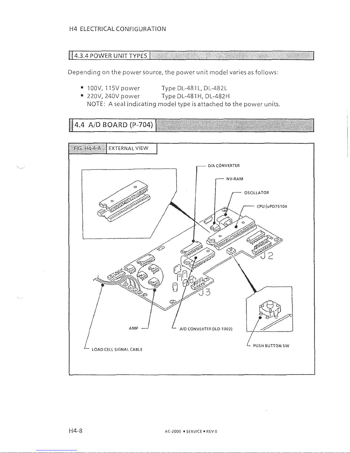
4.3.4
POWER
UNIT TYPES
I
,
,
, ,
I
Depending on the power source, the power unit model varies asfollows:
1
OOV,
11
5V power Type DL-481 L, DL-482L
22OV, 240V power
Type DL-481
H,
DL-482H
NOTE:
A
seal indicating model type
is
attached tothe power units.
-
DIA
CONVERTER
r
N;
oswAToR
CPU
(uPD75104
AMP
1
AID
CONVERTER
(ILD-1002)
L
LOAD
CELL
SIGNAL
CABLE
1
PUSH
BUTTON
SW
AC-2000
SERVICE
REV
0
Page 28
H4
ELECTRICAL CONFIGURATION
% %
. .
,
\
...
%.
%.
I
FUNCTIONS
[
"
A\'
I
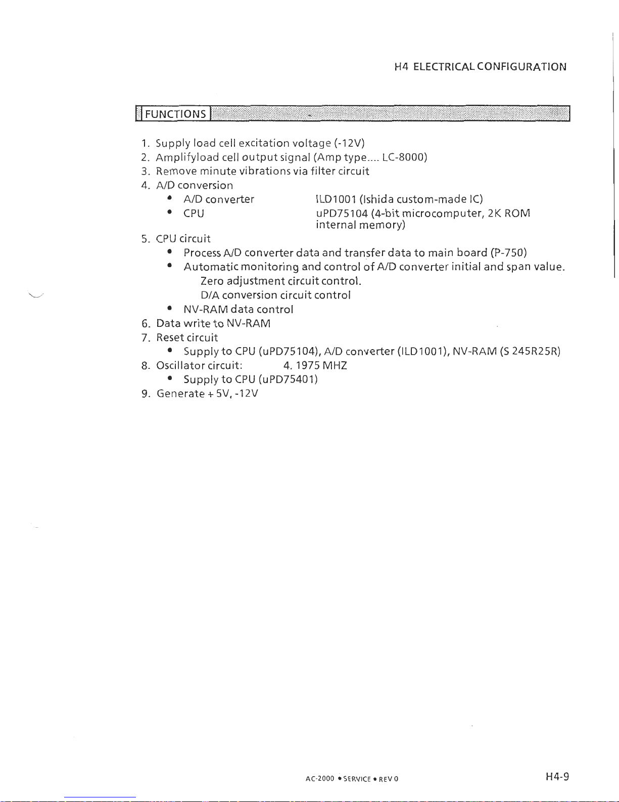
1. Supply load cell excitation voltage (-12V)
2. Amplifyload cell output signal (Amp type
....
LC-8000)
3.
Remove minute vibrations via filter circuit
4. AID conversion
AID converter ILDl001 (Ishida custom-made IC)
CPU
uPD75104 (4-bit microcomputer, 2K ROM
internal memory)
5.
CPU circuit
Process AID converter data and transfer data to main board (P-750)
Automatic monitoring and control of AID converter initial and span value.
Zero adjustment circuit control.
DIA conversion circuit control
NV-RAM data control
6.
Data write to NV-RAM
7. Reset circuit
Supply to CPU (uPD75104), AID converter (ILDlOOl), NV-RAM (5 245R25R)
8.
Oscillator circuit: 4.1975 MHz
Supply to CPU (uPD75401)
9. Generate
+
5V,
-1
2V
AC-2000
SERVICE REV
0
Page 29

H4
ELECTRICAL CONFIGURATION
16-bit microprocessors (V40)
(2),
control all data processing for AC-2000.
Multi-layered type, higly condensed component mounting, with lowered
electrical impedance to improve endurance against electrical noise and
static electricity.
ON
OFF
14
IC1
}
uPD71051G
IC4
J
2
J
1
TO
SCALE
AID
NOT
IN
USE
BOARD
P-704
H'4-10
AC-2000
SERVICE
REV
0
Page 30
H4
ELECTRICAL CONFIGURATION
14.5.2 FUNCTIONS
I
'
,
,
>"
I
Power input (VSI ,VS23, VH, Vcc)
Power reset (RESET, RSWO, RSW 1)
Weigh.data signal inputloutput control
All sensors (Label, scale, cassette) detection signal (AID conversion type) control
Display signal output (Dot matrix and multi-row displays)
Stepping motor control signal output
RS-232C inputloutput signal control (2 lines)
One of the 2 lines is also used for IFIRQ and fullkeyboard
12
Net inputloutput signal control (1 line)
Thermal head print data control
Cash drawer inputloutput signal control
Input/output signal control to ROMIRAM board.
Clock IC (Internal calendar) control
,
%%
,%
J*
,
.I
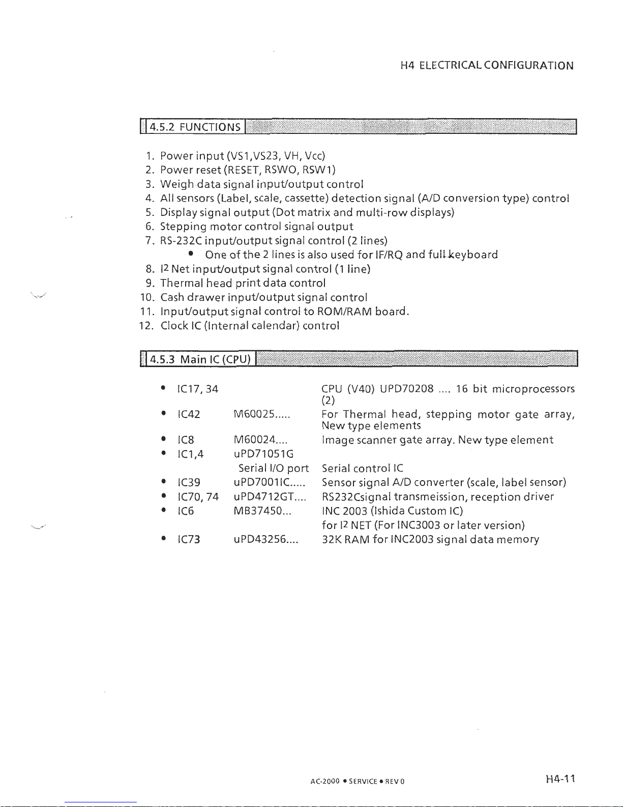
4.5.3
Main
IC (CPU)
I
,,
,2-,
.
,
.:
",
,
.
M6OO24
....
uPD71051G
Serial I10 port
uPD7001
1C
.....
uPD471 2GT
....
MB3745O
...
CPU (V40) UPD70208
....
16 bit microprocessors
(2)
For Thermal head, stepping motor gate array,
New type elements
Image scanner gate array. New type element
Serial control IC
Sensor signal AID converter (scale, label sensor)
RS232CsignaI transmeission, reception driver
INC 2003 (Ishida Custom IC)
for
12
NET (For INC3003 or later version)
32K RAM for INC2003 signal data memory
AC-2000 SERVICE REV 0
Page 31

H4
ELECTRICAL CONFIGURATION
~I,G.'HL~z~~
1
P-751
COMPONENTS
I
ROMiRAM SWlTCrilNG
IO
(CHiP2)RAM
11
ROlUTdNl
JP(IPI-IPS)
FOR
OPT~DNS
I~(CHIPI)
ROM
MAIN PROGRAM
ROM 12BK
IATTERY SW
LITHIUM EAT
3.8
V
ICI
(CHIPO)
MAIN PROGRAM
ROM 128K
IClO (CHIPO)
THERMAL
PROGRAM ROM
(12BK)
-
lCll (CHIP
5)
ROMIRAM
ROWRAM
SWITCHING
2
IP(IP6-JP10)
IC19 MN62a12
CHARACTER ROM (16x16) 115
CAUTION: Danger of explosion if battery
is
incorrectly replaced. Replace only with
the same or equivalent type recommended by the manufacturer. Discard used batteries according to the manufacturer's instructions.
AC-2000 SERVICE REV0
Page 32

H4 ELECTRICAL CONFIGURATION
,FIG.
H4-6-B
ROMlRAM BOARD EXTERNAL
VIEW
IC41 €2 PROM (8K)
IC42 RAM (128K)
Ill.,"
AC-2000 SERVICE REV
0
Page 33

H4
ELECTRICAL CONFIGURATION
>.
14.6.1
DESCRIPTION
I
, ,
1
1. This main board performst all contol functons for the AC-2000 software programs via ROM, character table ROM, Memory RAM (256 bite),
E2
PROM (8K
byte)
etc.
AID
converter data processing, totals data, thermal print data, sensor
data, keyboard input and output control and data backup functions are per-
formed here.
2. Program
Main Proqram
ROM Chip 0 (IC1) 128K bite (1 M bit) D27C100A 1 pc.
Chip 1 (IC2) 128K bite (lM bit) D27C100A 1 pc.
RAM Chip 2 (IC3) 128K bite (1 M bit) Available (option)
Chip 3 (IC4) 128K bite (1 M bit) Available (option)
Thermal Proqram
ROM Chip 4 (IC10) 128K bite (lM bit) D27C1001A 1 PC.
Chip 5 (IC11) 128K bite (lM bit)
ROWRAM
Available (option) 1 pc.
3. Ram staNdard package (POS type) soldered
HN62818L (IC42) 128K bite (1 M bit)
1
pc.
HN62818L (IC27) 128K bite (1 M bit) 1 pc.
4.
E2
PROM electonically programmable and erasable.
HN58C65 (IC41) 8K bite (lM bit) 1 PC.
5.
Character ROM (16x16) JIS standard
HN62412 (IC19) Hitachi
6. Clock circuit
Clock IC
MSM62X42
BRS
(IC9) CalendAr included (with leap year)
1
pc.
AC-2000
SERVICE 0 REV
0
Page 34

H4 ELECTRICAL CONFIGURATION
7.
ROMIRAM Switching (JP) setting
Location
NO.
Chip 3 (IC4)
Location No. Chip
5
(ICI
1)
[ROMIRAM switching available for socketted
chip]
JP
Switchinq Method
1
1
+
for
Switchirqlack
(JP)
2
;;::;:;:::
...
. . . .
2
Ill
1,Z
jumpersfor
RAM
)
JP Switching Range
CHIP
3
(IC4) sockets: JP1 -JP5
CHIP 5 (ICll) sockets: JP6-JP10
NOTE: This switching operation applies when options are being used.
At factory shipment, the
JP
swithcing position
is
on the RAM
side.
8.
Data Backup
Battery
Switch
Make sure the battery switch for memory backup
is
set to
ON
at time of de-
livery.
NOTE: This scale uses a rechargeable lithium battery; normal charge:
3.8
V.
Average life: 10 years. Battery switch
is
set to ON at time
of shipment from factory.
CAUTION: Danger of explosion if battery is incorrectly replaced. Replace only with
the same or equivalent type recommended by the manufacturer. Discard used batteries according to the manufacturer's instructions.
AC-2000 SERVICE REV 0
Page 35

H4
ELECTRICAL CONFIGURATION
1.
Remove the two main body casing screws at the rear of the scale.
2.
ROMIRAM board
(P-751)
is mounted here. 'The lithium battery and switch
1
are located
at
the lower center area.
#
1-
DISPLAY POLE
/
ROM/RAM BOARD
REAR COVER
3.
Remove the rear cover. Check that the battery switch is ON.
LITHIUM
BAUERY
(3L.W)
AC-2000
SERVICE REV 0
Page 36

14.8.1
FUNCTIONS
1
.
I
Each sensor (peeling, label, cassette) signal is communicated to the main board
(P-750) J8 via J5 jack, and flat cable.
CIRCUIT DIAGRAM
J
4
CASSETTE SENSOR
JST 81
4P-SHF-l AA
(NHCN)
13
LABEL SENSOR
JST
B6P-SHF-l AA
(NHCN)
12
PEELING SENSOR
JST 847-SHF-1AA (NHCN)
11
LCD
JST
87P-SHF-l AA
(NHCN)
AC-2000
SERVtCE REV
O
Page 37

H4
ELECTRICAL CONFIGURATION
THE AC-2000 uses
2
types of fluorescent displays: full dot matrix and 7-segment.
The full dot matrix display is used for displaying' alphabetical messages. The
7-
segment display is used to numerically display weight, price etc. For electrical conversion, a DC/DC converter
is
used.
(SV,
12
V)
0""
\
POWER DUDC CONVERTER
CAUTION
i
1.
Do not plug the cable in or pull out with the power switch turned on.
I
I
1
2.
Be careful toa-void applying shock or pressure to the display. When handling
I
I
the display with bare hands, be catfeful to avoid injury.
I
I
I
I
AC-2000 SERVICE REV0
Page 38

H4
ELECTRICAL CONFIGURATION
The peeling sensor controls label issue. The set cassette no. and label size determines tahe amount of label advance.
NOTE:
During label printing, if there is no label pqeling operation, the next label will not be printed. Label peeling
is
only activated during label
printing (according to cassette number). During receipt printing the
signal
is
disregarded.
PROJECT
14.1
0.1
FUNCTION
1
,
,
,
,
,,
^
When label advance starts and the label interrupts the light axis, the label
is
ad-
vanced the distance set. Therefore,
if
the label size are misset, the proper label ad-
vance cannot be executed.
AC-2000 SERVICE REV 0
Page 39

H4 ELECTRICAL CONFIGURATION
,
,
_(\
14.10.2 POLARITY
I
,,
,
,
-<
CI'
1
The sensor has polarity: take note when replacing.
P-612A face (Projectorside)
JP
P-612A face (receptorr side1
CATHODE
EMITTER
ANODE
Sensor Type: SE
307
COLLECTOR
Sensor
Type:
H
1
10
SENSOR RELAY BOARD
(P-755)
SENDER SIDE: ANODE To J2
1
pin
CATHODE ToJ2 2
pin
RECEIVER SIDE: COLLECTOR To
J2
3
pin
EMITTER
TO
J2
4
pin
AC-2000 SERVICE REV0
Page 40

H4
ELECTRICAL CONFIGURATION
The label sensor controls a stepping motor, which regulates label advance.
LABEL SENSOR EXTERNAL VIEW
The label sensitivity adjustment device with a flashing
LED
is located at the right rear
side
of
the main body.
ADJUSTMENT POINTS
AC-2000
8
SERVICE
REV
0
Page 41

H4
ELECTRICAL CONFIGURATION
*\
,
.
I.
\,
(4.1 1.1
LABEL
SENSOR UNIT
1
;
.
I
FUNCTIONS
I.
Sensor unit
The reqistered liqht siqnal is output to the sensor sensitivitv adiustment
< <
.,
,
board (P-545).
1
Sensor sensitivity adjustment board
(P-545)
For adjustment instructions refer to
H6.10
I
Output jack
Connected to the sensor interruption board
(P-755)
J3
jack
.:
....
..:.:.:.:.:<.:.:
........
.;.:>..
...
:.:.:.:.:
.:.::
:6f%Bi/ifS$-~~$fi:1:;:
........
LAB EL SENSOR EXTERNAL. VIEW
::,:::::;:,'::':'.:i(':jr;.jj.
.:.,,:
I.
Sensor:
Detects the lighting volume difference at label gap area, and
output signal to Sensitivity ad-
jurtrnent Board (P-545)
I
2.
Sensitivity Adjustment Board
(P-545):
To adjust proper sensitivity.
Refer
H6
6-10
,Sensor Adjust-
ment
3.
Output connector
TO SENSOR INTERRUP-
TOR BOARD
(P-755)
J3
,:.:
..;.
:i.,:::::.:j:':.
.......................
~~I~~~,B$-z~~z:<:I
.:...:.:..'
......
:.:
...
......................
...
.:
::
....
SENSOR INTERRUPTION BOARD (P-545)
1
.......
BROWN,
,
BLANK
LED
BLACK
CONNECTOR COLOR
I
P-545
I
1
BROWN
1
2
RED
2
3
ORANGE
I
3
4 YELLOW
1
4
5
GREEN
I
5
AC-2000
SERVICE
REV
0
Page 42

H4
ELECTRICAL CONFIGURATION
FIG.
H4-23;A
CASSETTE SENSOR AND SENSOR SEAL LOCATION
SEAL
INDICATING NO.
CASSETTE
-
-
CASETTE SENSOR
SEAL ATTACHED TO REAR OF THIS PART
I
.,
,
.
CASETTE SENSOR AND CASS.ETTE
NO.
1
,'
1
The sensor is equipped with a photo interupto. When the sensor seal interrupts the
light beam the cassete sinal is dettected.
By
combinations of the cassette signals, the
cassete number is determined. Sensors
1-4
are combinations of
1,2,4,
and 8 for
a
total of
15
possible combinations.
NOTE:
Cassete no.
0
is
not available.
SENSOR
1
(2')
=
2
SENSOR
1
(20)
=
1
SENSOR 1 (22)=4
SENSOR
1
(23)=8
AC-2000 SERVICE REV
0
Page 43

H4
ELECTRICAL CONFIGURATION
Note the following points:
1.
Cassette
number and sensor number must be correct
2.
Cassete seals at front and rear must match
3.
Take care that the seal does not fall off
CASETTE
(2-1
5)
I
I
LABEL
WIDTH
ADJUSTMENT
I
9
I
n
f7
Set
the label width
to conform
with the users
requirements.
LABEL
GUIDE
LABEL
GUIDE
I
Align the 2 label
gu~des
with the width of the roll
SCREL;,
\-d
SCREW
AC-2000
SERVICE REV
0
Page 44

H4
ELECTRICAL CONFIGURATION
FIG.
~4:25-~.
I
EXTERNALVIEW OF
SIDE
PANEL CONNECTOR
-.
CONECTOR
4
'
'
CAP
CONNECTOR
1
:
Available at time of System start-up (i2 NET)
2:
R
I1 I1
,I
3
:
Cassette Loading (RS-232C)
4
:
Option (RS-232C)
NOTE: Please cover unused connectors with caps
AC-2000
SERVICE REV
0
Page 45

H
5
THERMAL
HEAD
This chapter describes the mechanical confi uration and electrical adjustment of the
thermal head as well as information relate to its function. The following items are
covered
:
3
Specifications
Thermal head configuration
Function
Adjustment
)
Mechanical adjustment
)
Head resistance and print density adjustment
This thermal head
(€60-74C
Mitsubishi) used
is a 448
dot high resolution type with
7.4
dotlmm. The printing is configured one row at a time.
NOTE:
Do not use a different type of thermal head in the
AC-2000.
I
I~oltaqe
0.84
W or less
I
Total Dot count
Dot dimensions
Resistance
Voltage dropdown
1
V
Head Print Volt. Max VH
+
Rx0.84
+
1
V
448
dots
0.135
mm
(W)
X
0.155
mm
(H)
R
=
600-700
ohms
AC-)000
SERVICE
8
REV
0
Page 46

H5
THERMAL HEAD
FI~.
H-5-3-A
I
HEAD RESISTANCE
1
Head
resistance
value
-b
RXXX
Surface Pattern:
rear view
Head resistance
(Q)
1
RG.
5-i-0
I
CIRCUIT DIAGRAM
I
I
1
I
CATCH
I
I
I
DATA
0
448-------
--I
1
CLKo
I
J
AC-2000
SERVICE REV
0
Page 47

H
5
THERMAL HEAD
,
U
5.4.1
ADJUSTMENT ITEMS
I
I
1.
Mechanical adjustment
2.
Thermal head resistance value adjustment
3.
Strobe pulse duty ratio adjustment
[I
5.4.2
MECHANICAL ADJUSTMENT
I
,
,
,,
,
,
A,
I
1.
Purpose
In order for the thermal head to print out a line, the head's line and the top line
of the print roller must be aligned to the same position. If misaligned ,the entire width of the line will not be printedclearly. By adjusting the installation position of the thermal head, this adjustment can be made.
2.
Adjustment Method
Loosen the
head screws, and align the thermal head and sii htly retighten
3
the screws. The head should be aligned so that the the printe characters are
sufficiently and consistently darkthroughtout a line. Finally, tighten the head
screw.
[::FIG.
54-A
1
ADJUSTMENT POINTS
Y'
""
-
'
%.;.
'
.
NOTE:
The print roller is made slighly wider in diameter compared with previous
models so that clear, consistent printing
is
still
maintained even
if
roller and head is
slightly misaligned. To ensure correct adjustment, change the Head resistance value
higher, only for adjustment purposes.
AC-2000..4
S~RVICE
4 REV 0
Page 48

H5
THERMAL HEAD
15.4.3 THERMAL HEAD RESISTANCE ADJUSTMENT
I
%
,<
,
I
Purpose: To compensate for variations of head resister value and ambient tempera-
ture variations. AC-2000 controls the apply voltage duration timning in-
stead of varying head voltage.
Applied voltage
is
fixed at 24V.
The method of adjustment
is
as follows:
1.
Press number 3 in the test mode
2.
Press the DOWNISET key.
3.
The
Head
Check
display appears.
4.
Align cursor with the resistance value setting position
5. With the key switch in the SET UP position enter the resistance value (inscribed
on the thermal head) via the ten-key pad and press the DOWNISET Key.
6..
Press the PRINT key to print the test.
7-
Ln
th.isconditim.d.ensity
can
be fine adjusted via-the up and down cursor keys
NOTE: For details on the Test Mode, see Chapter 55.
KEY
SWITCH
AND
TEST PRINT
LABEL
I
KEY
SWITCH
I
TEST
PRINT
LABEL
To clear the PRINT USAGE value:
Align cursor with the PRlNT USAGE item and press the ZERO Key
2
times. The
cursor will shift simultaneously with clearing. Always perform this procedure
when replacing the head.
AC-2000
SERVICE
REV
0
Page 49

H
5
THERMAL
HEAD
15.4.4 STROBE PULSE DUTY RATIO ADJUSTMENT
(
*',
,
'*
,
I
Depending on the printing frequency and the ambient temperature, the thermal
head temperature will vary. This means that printing quality may vary when using
high-sensitivity labels or receipts. For this reason the pulse duty ratio is adjusted.
MAIN
BOARD
P-750
TP1 is set to 3.3 V at time of factory shipment (VR1). Do not
set
to other than the
prescribed level.
To adjust:
1. Measure the voltage between TP1 and TP3
(GND).
2.
Adjust to 3.3 V.
3.
The normal temperature can be diagramed as the following wave pattern.
0.8
msec
l-1
NOTE: There
is
normally
no need to set the strobe
pulse ratio
(64%).
When
needed set via (VR1) only.
I+-+
1.25
msec
AC-2000 SERVICE REV 0
Page 50

H6
ADJUSTMENTS
This chapter deals with mechanical and electrical adjustment points. For thermal
head-adjustments, refer to Chapter
H5.
1.
Four-corner limit adjustment
2.
AID
converter initialization value and span adjustment
3.
Peeling sensor and label sensor adjustment.
A limit is provided
by
the platter stand to protect the load cell from excessive
external load. Adjustment
is
made at each corner of the platter supporter.
AC-2000
SERVICE
REV
0
Page 51

H6
ADJUSTMENTS
€l6:,&3-5
I
ADJUSTMENT POINTS
I
,
,,>
I
CUSTOMER SIDE
I
I
SHOP CLERK SIDE
I
1. For each corner
A-D
consecutively, place a capacity weight + 1Kg on the
corner.
2.
Loosen the fixed nut and turn the limit adjustment screw so that
it
contacts the
upper case set screw.
3.
Tighten the fixed nut.
NOTE: This adjustment
is
necessary when replaing load cell or excessive load
is
applied to the load cell.
If
the
AID
value falls outside a certain range, the scale cannot compute the weight.
The initial value adjustment ensures that this range
is
maintained.
1
ADJUSTMENT PROCEDURE
1
I
1. Press the RESET Key then immediately press any key. The
TEST
MENU
display
will
appear:
I
TEST
MENU
[PAGE]
113
1
:
HARDWARE TEST
2.
RAM CLEAR
3:
THERMAL HEAD
4.
SENSOR CHECK
(
0)
AC-2000 SERVICE REV 0
Page 52

H6
ADJUSTMENTS
2.
Enter
#1
and press the DOWNISET Key. The Hardware Test Menu display will
appear:
[PAGE]
113
1
:
AID
CHECK
2.
KEY CHECK
13:
DISPLAY CHECK
4.
PROGRAM
No.
I
3-
Enter#l and pres the DOWNISET Key.
The AID Check Display will appear.
AID CHECK
FIGURE
(9)
[PAGE]
113
*AREA+(SET] ZERO POINT+[ZEROI
I
The AID value will be displayed. In this mode the AID check, AID initial value adjustment, span adjustment etc.
is
performed.
NOTE: Refer to Chapter
55
for more detailed information onTest Mode.
AC-2000 *'SERVICE REV
0
Page 53

H6
ADJUSTMENTS
1.
Press the
ZERO
Key. The
AID
value display will show "0",
2.
Place the span weight specified below on the weigh platter
130
LbISingle Range
I
30~b
I
CAPACITYIRANG E
*
15 KgISingle Range
Press the
UP/T
Key.
Verify that the
AID
display shows 3Q,000 count during span adjustment,
Remove the span weight from the platter.
To perform fine span adjustment, place the span weight on the platter and
press the up and down cursor'keys
AV.
After span adjustment or initial
AID
adjustment is completed, press the button
on the
AID
board.
SPAN ADJUST WEIGHT
15
Kg
AC-2000
SERVICE
REV
0
Page 54

Page 55

H6
ADJUSTMENTS
Purpose: The adjustment is made to prevent notch feeding of label in case the axis
of sensor
is
misaligned by external interference
SENDER SIDE
PLATE
SENSOR LIGHT SHAFT
-
-\
SENSOR ATTACHMENT SCREW
I
'
SENSOR ATTACHMENT PLATE
16.7.1 ADJUSTMENT METHODS
1
',
1.
Loosen the sensor attachment screw and align the light axis.
2.
Move the sensor attachment plate and align the light axis.
3.
Align the light axis by bending the plate on the label sensor receiver side.
8,
,,
,
.
16.7.2 ADJUSTMENT VERIFICATION
1
, ,
A)
, ,
.
A,z,
*-A
,,.
%
I
See Chapter
55:
5.6
Test Mode.
AC-2000 SERVICE *REV 0
Page 56

H6
ADJUSTMENTS
1
(
6.7.3
PEELING SENSOR SENSITIVITY LEVEL VALUES
I
,
,,
Y
,
The sensitivity count show. Therefore the peeling sensor value which
is
displayed in
test mode
4
corresponds to the count as shown below.
Count standard value
(Count
+
0.02V.)
Peeling sensor voltage at time of light transmission
........
1 volt or less
Peeling sensor at time of light interrupt
....-...
4
volts or less
Therefore the Peeling sensor count is:
Peeling sensor voltage at time of light transmission
........
50
count (1 volt) or less
Peeling sensor attirne of light interrupt
........
200 count
(4
volts) or less
,
,
11
6.7.4
CAUTION POINTS
I
:\
Make sure there
is
no foreign matter on the sensor components
Verify power activated condition (Test Mode)
.A.
In the test mode menu enter
'4'
and press the +Down Set Button
2. The sensor check screen will appear:
SENSOR CHECK
[PAGE]
113
LABEL [255]
CASSETTE
[I]
CHECK
PEELING
[01
AC-2000 SERVICE REV 0
Page 57

H6
ADJUSTMENTS
~djustment Method A
1.
Turn the Fine Adjustment
VR
all the way counterclockwise.
2.
Press the Feed Key lightly one time, and turn the fine adjustment
VR
clockwise
until it corresponds with the position of one label advance. This
is
position A.
3.
Turn the Feed VR all the way clockwise.
4.
Press the Feed Key lightly one time, and turn the fine adjustment VR counterclockwise until it corresponds with the position of one label advance. This
is
posi-
tion
B.
5.
Set the VR halfway between positions A and
B.
NOTE:
If
B
cannot be determined, rotate the rough adjustment
VR
clockwise a lit-
tle and perform procedure again from
1.
Adjustment Method B (When range cannot be determined via fine adjustment VR)
1.
Align the Fine Adjustment VR to the center position.
2.
Turn the Rough Adjustment
VR
all the way cou&erclockwise.
3.
Press the Feed Key lightly one time, and turn the rough VR counterclockwise until
it
corresponds with the position of one label advance. This is position
C.
4.
Turn the Rough Adjustment VR all the way clockwise.
5.
Press the Feed Key lightly one time, and turn the Rough Adjustment
VR
counter-
clockwise until
it
corresponds with the position of one label advance. This is posi-
tion
D
.
6.
Set the VR halfway between positions C and
D.
7.
Perform Method A again.
NOTE: Upon delivery or during regular check of the scale, set
B
after setting A.
AC-2000 SERVICE REV 0
Page 58

H7
INSTALLATION
1.
Open the carton and check the scale and
its
components for damage.
2. Attach the weight platter and the display unit (including the pole).
3.
Insert power plug into a power outlet.
4.
Perform the Initial Set Up procedure in Test Mode 2 (page 212).
5.
Perform RAM clearin Test Mode 2 (page 112).
6.
Set the scale to conform to the users requirements:
Label format, label advance distance etc.
7.
Register the day and time.
8.
Register PLU Master Files etc.
9.
Insert the label or the receipt cassette, and determine if printing quality is nor-
mal.
10.
Clear Totals.
11.
Download all registered data to cassete or floppy disk as back-up.
12. Perform aging with the power
SW
still on.
NOTE: The installed lithium battery requires no aging
(10
year life-span).
AC-2000 SERVICE
REV
0
Page 59

H8
MAINTENANCE
This chapter contains cleaning, inspection, maintenance, and troubleshooting pro-
cedures for the dealer and user so that the scale
is
kept in its best operating condi-
tion.
When there
is
a malfunctioning unit reported by the user, unit replacement
is
the
usual countermeasure. The following table shows the necessary specifications for
the components used in the AC-2000.
PART NO. PARTNAME
I
SPECS
I
NOTES
I
I
1
PWB, P-750' B l~ain Board
I
I
I
PWB, P-751' A
1
RAM
board
1
I
PWB, P-752' A Keyboard
PWB, P-753' A Connector BKT
PWB, P-755'
Sensor interrupt
1
board
PWB, P-756'
Cassette sensor
1
board
I
PWB, P-704' D AID board
LC
Unit, CLC-25L 15 Kg130 lb
Stepping motor AS Orental PH266-01-C48
Fluorescent display URA
UDD-348E
Power supply
Sanken Main
D L-482
L
switchinq
1
OOVl115V
Power supply Isanken Main
I
DL-482
H
switching 22OVl24OV
Power supply
switching
I
Sanken Thermal
100V1l
5V
I
DL-481
AC-2000 SERVICE 0 REV 0
Page 60

H8
MAINTENANCE
AC-2000 SERVICE 0 REV 0
No-
"
16
17
18
PARTNO.
16-6527-01
18-3003-00
18-3004-03
09-2755-1 1
PART NAME
Power supply
switching
Fluorescent display
panel
Fluorescentdisplay
panel
Label sensor unit
SPECS
Sanken
Thermal
NEC
NEC
NOTES
DL-481
H
ZZOV,240V
FM256GX64
AB-100A
FM-PIS-001
P-545C, PN 150
(C)
Matsushita
Page 61

H8
MAINTENANCE
1.
Thermal head printing surface
If ink, glue or dust from the label gets stuck to the thermal head print surface,
heat will not be properly transferred to the label causing poor print quality.
2.
Print roller
The print roller drives the label feed. If dust from the label gets stuck to the
roller,
it
could cause improper label feed.
NOTE:
Clean with the attached cleaning pen dipped in filtercleaner.
When the cleaning pen and filter cleaner are not available, wipe with a
clean cloth moistened with benzene.
When cleaning the head be.very careful not to scratch or damage it.
Never use thinner for cleaning the head.
3.
Label sensor
-
Do not clean the label sensor with hard or abrasive materials
If foreign matter attaches to the sensor sensitivity will be reduced and
malfunction may result.
AC-2000 SERVICE
REV
0
Page 62

H8
MAINTENANCE
The inspection points listed below should be performed by the operator as a habit.
Early detection of
a
problem not only ensures proper machine operation but
extends machine life
as
well.
Be sure to turn power off when performing inspection. Turn power on only when
required to check operation.
-
No.
-
1
-
2
-
3
Inspection kern
Remove scrap prod"&
from and clean scale
surface
Remove scrap product
from and clean inside
scale.
Check installation and
operation
Location
I
Rernarl
Weigh Platter
Upper Case
Main Unit Base
Front Cover
Side Cover
Keyboard Sheet
Display
Level Window
Use
dry
cloth.
Underneath Platter
Label sensor
Cassette
Thermal Head surface
Print Roller
Use dry
clothlcleanin!
Check level (visually).
Touch scale; check that it
is
affixed securely.
Check that label feed
is
smooth.
Check each key function.
Check display.
CAUTION
-
I
f
Be
sure to turn power off when performing inspection. Turn power on only
1
when
it
is
requred-to check operation
I
I
L-----------------------------------------------------------------------------A
AC-2000 SERVICE REV
0
Page 63

H8
MAINTENANCE
Pre-maintenance procedures should be performed every 3-4 months.
8.5
PREVENTIVE MAINTENANCE
-
lo.
-
1
2
-
3
-
4
-
5
-
6
-
%
,
,,,
%,,
,,"$,,
'C
,
:,
Inspection Item
I
Location
lemove scrap product
rom and clean scale
urface
Weigh Platter
Upper Case
Main Unit Base
Front Cover
Side Cover
Keyboard Sheet
Display
Level Window
temove scrap product
rom and
clean
inside
cale.
:heck installation and
)peration
Underneath Platter
Label set location
~hermal Head surface
print Roller
Check level (visually).
Touch scale check that
it
is
affixed securely.
Check that label feed
is
smooth.
Feed should be quiet
Check la be1 sensitivity
adjustment
Check print position
etc.
Check display on store and
customer sides.
Check A/D value output
including initial and span
values.
Check label take up.
Inspect friction plate for
dirt.
Check print quality.
Zheck parts functions
Check that screws are
tight and connectors
are plugged in securely
Check function keys for
intermittence, chattering,
Thermal head cable.
External output connect01
rust (for cassette loading).
Printer.
Remarks
Ise
dry cloth
Other
Jse
dry cloth
Four corner load cell limit
adjustment.
Print roller damage.
Jse
cleaning pen
Use span weight.
Visual inspection
AC-2000
SERVICE REV
0
Page 64

H8
MAINTENANCE
[I
8.5.1
MAINTENANCE CAUTIONARY INSTRUCTIONS
I
z
:,,
A
,
'
.,
,
,
,"
,
..,,
,
,
I
Be
sure to follow the items below to ensure personnel safety when performing
maintenance, disassembly, assembly, adjustment and pre-maintenance.
1.
Turn power
OFF
and unplug power cable from socket and detach completely.
2.
Clear surrounding work area. Remove label set on printer.
Be sure that no parts, screws or papers fall into the internal mechanisms or
electronics during maintenance.
3.
When plugging in or unplugging connectors, be sure to rip the connector and
not pull by
the
cable wire. In particular, malfunction oft
8,
e thermal head cable
can result in temperature detection failure resulting
in
overheating.
4.
Take extra care when cleaning the thermal head and print roller to avoid
scratching their surfaces.
5.
Be sure to follow all instructions for assembly and adjustment procedures
completely.
AC-2000 SERVICE REV 0
Page 65

H8
MAINTENANCE
p,
9,'
5, %
2"
.
..
.:g
'
,,
,
<..
,
,
...,
8.6
TROUBLESHOOTING
,
I
The following causes for malfunction are the most probable and common ones.
Other factors may lead to abnormal functioning of the scale.
AC-2000 SERVICE REV 0
Page 66

H8
MAINTENANCE
-
No.
-
1
-
2
Condition
llank display when
lower turned
ON
kale enters Test Mode
after power switch is
urned on
'Just a moment! Scale
swarming up!"
lisplay does not extnguish
'Just a moment! Scale
swarming up!"Dis)lay appears when
3ower turned on.
Neight, price. unit price
jisplays read "0".
Neigh reading in error
3
r
Nei h reading varies by
tse
I
9
I
display column or
;egment doesn't light
3r does not extinguish
Probable Cause and Checkpoints
1.
Power cable not plugged in.
2.
Main fuse is blown.
3.
Voltages absent on
JlO,
Jl,
J14on Main
Board (P-750)
a. Connector unplugged.
+Check power unit side, too.
b. Connector miscontact.
+Check power unit side too.
c.
Faulty power supply unit
+Check
Vcc
(
+
5V) 7-segment display.
+Check Display drive V12 (Dot display)
(+
SV)..
+Check RST
is
<3V
4.
Main board defect
5. ROM, RAM board defect
6.
Power Switch defect
7. Power switch connector defect
1.
Key board short circuit
2.
Main board defect
-his indicates that the initial AID value
is
most
ikely unstable;
1.
Load cell defective
2.
External vibration influencing weigh
components
3.
Defective main board amp circuit
4.
Defective power unit (unstable
+
8V,
-1
5v)
1.
Check Key switch cable and its connection
2.
Key SW defect
3.
J2
connector on Key board (P-752) contact
defect
4. J4 connector on Main board (P-750) contact
defect
1.
Mechanical fault.
a. Lo-ad cell or
its
mount
is
hitting limiter.
b.
Foreign object stuck under or contacting
platter.
2.
Electrical Fault.
a. Defective Load Cell
b. Main board amp circuit defect
1.
Program not running
2.
J5 connector on Main board (P-750) contact
defect.
3.
Main board (P-750) defect
4.
Display board defect
AC-2000
SERVICE
REV
0
Page 67

H8
MAINTENANCE
-
'lo.
-
7
Condition
i<ey fault
3egisttered information
altered
Display goes out
completely during
operation
Label or receipts not
printed
Prints only on left or
right half of paper
"Check Label Cassette"
message appears
"Remove The Item on
the Platter" message
appears
NV
RAM Data Lost"
message appears
"RAM Data Lost"
message appears
"Mark Down Price
Over" message appears
Probable Cause and Checkpoints
1. All keys fail to operate.
a.
J4
connector on Main board (P-750) pulled
out
b. Main board (P-750) defect
2. Specific key fails to operate.
a. Key or key matrix problem.
+Cable open or poor connection.
+
Main board (P-750) defect
+
Key board (P-752) defect
--
1. Battery defect
2. ROMI Ram board defect
3.
Influence from external noise, static
electricity
1. Drop in AC input voltage.
2. Power unit reset circuit defect.
1. Contact defect in thermal head cable
2. Thermal head print voltage out
a. Power unit defect
b.
Check thermal head resistance value
(Head Check) via Test Mode
3
3.
Main board (P-750) defect
4. Thermal head defect
1. Main board (P-750) defect
2. Thermal head defect
3.
Strobe signal (either STB1 or STB2) not active
4. Thermal head connector cable defect
1. Cassette mis-inserted
2. Label or receipt specifications misset
a. Check Set up mode, Label Format.
b.
Check cassette sticker
3.
Cassette sensor defect
a. Check Test Mode 4, Sensor Check
4. Main board (P-750) defect
1. Check that platter is clear
1. Reset initial value data
2.
NV
RAM defect
3.
AID board (P-704) defect
1. RAM data lost, Clear RAM data (Test Mode 2)
2. ROM, RAM board (P-751) defect
3.
Main board (P-750) defect
1. Check mark down price
AC-2000 SERVICE REV 0
Page 68

H8 MAINTENANCE
\lo. Condition
17
"Memory Over"
message appears
I1'Over Character1'
message appears
"Over CharacterIPOP"
message appears
20 "Over CharacterIReg."
message appears
21
"Label End" message
appears
-
22 "Label Size Error"
message appears
"Label Size Set Error"
message appears
Probable Cause and Checkpoints
1.
During operation: Remove totals report and
clear totals
2.
During registration: Remove totals report
and clear totals. Or Delete unnecessary; PLU.
If necessary take backup via IFIRQ, and Clear
ram
(
Test Mode
2)
1. Re-register (Too many characters in
registration item.)
1.
Re-register (Time of ad messagetoo long.)
1. Re-register (Excessive Reg. code)
1.
Label paper end.
.2.
Cassette defect
a. Label advance mechanism defective
3.
Motor not rotatin (stepping motor)
a. Cable contact efect or connector contact
defect
3
b. Motor defect
c. Main board (P-750) defect
d. power unit (DL-481 side defect
4. Peeling sensor defect (Test Mode 4)
Only when label
is
not inserted after
peeling sensor catches the label end
1.
Check label format setting
2. Set to
1
via Key Switch
1.
Check labelformat setting
2.
Set to 1 via Key Switch
AC-2000
SERVICE
0
REV
0
Page 69

H9
PARTS
This chapter contains the principle parts used in the AC-2000.
SPECIFICATION.
OPERA TlON UNlT
--
I
Keyboard
Key Sheets (Normal, Totals, [Test Mode])
P-752
one of each
Switch Key (Operator's, Supervisor's)
I
one of each
LOAD
CELL
UNlT
I
Load Cell
1
CLC-25L (1 5Kgl301b)
Rated Capacity 25 Kg
I
.,
Rated Output 1.95 mvN
Input Resistance 405
2
1OQ
Output resistance 350
2
5R
A l D BOARD
(P-
704)
I
AD converter
CPU
I
ILD1001 (Ishida custommade IC)
uPD75104 (4 bit microprocessor;
2
KROM internal)
DIA converter
Analog SW (M-ultiplexor)
CPU (V40)
1
uPD75208
DAC0832
D4053
Power Regulator
NV-RAM
MAIN BOARD (P-750)
Gate array
1
.M60025
,70L05,79L12
S2444R (S24S45R)
AC-2000
SERVICE REV
0
I
12
NET transmission
M37450 (INC2003 lshida
custom-made IC)
Page 70

H9
PARTS
U
NITIPART
I
SPECIFICATION.
I
RS
232C Buffer
1
uPD47129
AID Convert
RS
232C Signal Transmission.
ROM I RAM BOARDS
(P-751)
I
uPD7001C
uPD71051G
I
Clock IC board
I
MSM62 X 42 BRS
Character Table ROM (1 6x1 6)
RAM (POS type) soldered installation
HN62412FPW01 (Hitachi)
HN628128L (128K) (Hitachi)
ROM (program)
Data switchover board
DISPLA Y UNIT
I
Fluorescent display DCIDC converter
I
UDD-348E
uPD27C100A
(1
28K)
HC541 P (Tri-State)
7-Segment display
X-Y Matrix fluorescent display module
CASSE77E SENSOR
I
FNI-PIS-00 1
.FM256GX64AB-l00A
PEELING SENSOR
I
Photointerruptor
LABEL SENSOR UNIT
PS4005 (NEC)
P-545C; PN 150 (Matsushita)
MOTOR
1
Projector side (on P-612)
Receiver side (on P-612)
SE
307 (NEC)
PH 110 (NEC)
AC-2000
SERVICE REV
0
Stepping motor
THERMAL HEAD
PH266-01 (Oleander)
E60-74C (Mitsubishi)
Page 71

S1
OUTLINE OF SOFTWARE
I
1
.I .I
MEMORY
MAPS
I
,
\
,
,*~
I
The memory map below refers to the main side memory data and Test Mode 6 described
in
Chapter
5.
ADDRESS
FFFFF
EOOOO
DFFFF
C0000
BFFFF
AOOOO
81
FFF
80000
5FFFF
40000
3FFFF
20000
IFFFF
0000
ROM (Ic1)
STANDARD FITTING
ROM (w
STANDARD FITTING
E2
PROM (IC41)
ROMIRAM (IC4)
(Option: RAM mode
at shipment
RAM (Ic3)
(OPTION)
RAM (Ic4)
STANDARD FITTING
ADDRESS
FFFFF
EOOOO
BFFFF
80000
5FFFF
40000
IFFFF
0000
(IClO)
STANDARD FITTING
STANDARD FITTING
I
I
1
ROMIRAM (IC11)
(Option: RAM mode
at shipment
1
RAM (IC27)
STANDARD FITTING
AC-2000 SERVICE REV 0
Page 72

51
OUTLINE OF SOFTWARE
RAM (IC
27)
is
used for printing (Initiated from the Main CPU side)
I
ROMIRAM
board
(P-750) Part
Side
1
I
ROMIRAM
board
(P-750)
Soldering
Diagram
E2
PROM
THERMAL
I...{
*,
'
I,
1
1.1.2
RAM
EXPANSION
.
~,
.
To increase RAM to add PLU, add in this order: IC3, IC4.
USE ONLY RAM PROVIDED BY ISHIDA'S SERVICE CENTER.
IF OTHER RAM ARE UTI-
LIZED, ISHIDA CANNOT BE RESPONSIBLE FOR MALFUNCTION.
AC-2000 SERVICE 0 REV 0
Page 73

51 OUTLINE OF SOFTWARE
PLU' NO.
ITEM
'CODE
POS CODE FLAG
.DESCRIPTION
ITEM LENGTH
POS CODE
UNIT PRICEIFIXED PRICE
FIXED WEIGHT
BITE COUNT
2
I
TARE
I
2
I
MARK DOWN FLAG
MARK DOWN DATA
1
3
POS FLAG
DATEfllM
E
MESSAGE 1-6
SHELF LIFE
USE
BY
PERIOD
FIXED PRICENVEIGHT FLAG
2
2
1
I
1 Character:
I
1
Bite
TAX
TAX RATE
FIXED LENGTH
46
BITES
1
2
MAX 1001 BlTE
(including
header
1
bite)
NOTE:
1. Start address for PLU Master is E000.
2.
No totals data is contained in PLU master file. The totals data
is
contained in the
area subsequent to the PLU master file (See 53).
AC-2000 SERVICE *,REV 0
Page 74

51 OUTLINE OF SOFTWARE
Fixed length
is
42
bites (totals are in separate area).
Product code is different from the POS code.
When the POS code
is
the same as the product, POS code registration
is
unnece-
sary.
Cost can only be registered as product information (not yet in use)
Mark down flag: 00
:
SPCL
01
:
-$
02
:
-%
03 : UIPrice
Expiry date/
Use by date
FF,
FF
:
Refer to
Set
Up
Mode
0
:
Prohibited
PRlNTlNG
1-998
:
Pack time, Shelf Llfe
999
:
Packtime only
1001-1998
:
Shelf Life only
Fixed pricelweig
ht
flag
00
:
Random weight
01
:
Fixedprice
02
:
Random weight WITH fixed price
POS flag
FF : Conform to Set Up Mode
01
:
13 digit Non-PLU
01
:
I3 digit PLU
Daterrime 00: Non printing
1-11
:
Manual print AM
**
I
PM**
12-23
:
24
:
AM) NOTE:
98
:
Internal timer print
It
is
necessary to modify format to print out Daterrime.
PLU file: Characters: One character bite (ASC 1 lcode)
Dictionary Word
:
2 bites per word
Example: A dictionary word
starting with the letter
"A"
C1H **H
Word reg. sequence No.
Code indicatin word
configutration
starts with
'4".
8
added
and contents
may
to
ASCII
bit (upper
---.A:--\
I
vary by country
I
puslLlurl,.
AC-2000
SERVICE REV
0
Page 75

S1 OUTLINE OF SOFTWARE
,I
[I
ITEM CODE AND POS CODE
1
,
,
1.
If the POS code registered in PLU item is
0,
the Item code
is
as shown here:
1
1
XX XXXXXXXXXX
POS
CODE
-
10
DIGITS
POS CODE
FLAG
POS CODE
2.
When PLU file POS code flag is SET FF
Conforms to setting input
in
Set UP Mode. When not FF, The POS code for the
PLU file takes precedence.
3.
When PLU file POS code is
"0"
Print according to the ITEM code. When not
"Ow,
the POS code for the PLU
file takes.precedence. The POS code for PLU items all take precedence.
AC-2000
SERVICE REV
0
Page 76

S1 OUTLINE OF SOFTWARE
1
1.3.1 CHARACTER TABLE
I
%
,
<,
,,
,,,
I
Three types of font, two of which have
X2
&
X4
size are available. (Total character
styles:
7)'
Type
3
15x30
I
30x60 1 650x120
dot
I
dot
I
dot
I
I
------------,-------------------------
I
I
I
I
I
I
I
I
I
I
I
I
1OX2.0
1
20x40 ( 4OX 80
dot
I
I
dot dot
......................................
I
I
7x14
I
dot
I
I
I
I
I
NOTE:
1.
The dimensions of one dot are:
0.15
mm
2.
Character selection may be limited
0.135
mm
according to the registration item.
AC-2000
SERVICE REV
0
Page 77

S1
OUTLINE OF SOFTWARE
The characters shown in the following chart do not appear on the keyboard but are
available.
METHOD:
Example: To access the exclamation mark:
1.
Press the
FEED~SHIFT
~e~.
2.
Press21.
3.
Press the
PLU
Key.
AC-2000 SERVICE REV
0
Page 78

S2
LABEL FORMATTING: USA
It is possible to modify label formats or move printed contents to comply with the
customer's requirements. The location data
is
stored in
E2
PROM so there
is
no need
to change
it
via.PROM Writer.
NOTE: Transaction labels or total label printing formats are subject to Weights and
Measures approval.
A
change of format or deletion of printed information may re-
sult in non-compliance with Weights and Measures regulations. Please use the ut-
most caution when changing or modifying the printing format.
This section will describe the actual dot printing size and coordinate setting.
The
AC-2000
is
equipped with a double density type thermal head, but labels are
printed at double density. Printing coordinates are
set
using double density specifi-
cations. Single density dot
size
is as shown below:
AC-2000 SERVICE REV 0
Page 79

S2 LABEL FORMATTING: USA
COORDINATES AND PRINT FORMAT LAYOUT
f
\
<,
,,,,X.
I
Labels are configured into four data columns as shown here. Only the upper and
lower column data can be modified.
Y axis
i
Origin of
Cooridnates
+
(0,O)
____+
X
axis
Table
Upper data column
Product Name column
Lower data column
Store name and address
column
Product name column
Column name
Upper data column
Product name. Number of lines
is
entered
via setup mode.
1
line
=
8
dots = 2.5mm
Data
is
cleared when a new PLU name is
called up
Specifications
Data which appears above the product
name (digits, bar code). This area is
cleared each time a label is printed.
Lower data column
AC-2000
SERVICE
REV
0
Digits and bar code printed between the
Store name and address and the product
name columns. Data
is
cleared when a
new PLU name
is
called up
Store name and address
column
Pre-printed store name and address print
area
Fixed at 2.65 dots (7.5MM)
Page 80

S2
LABEL
FORMATTING: USA
For entering actual cooridinates, think of the data columns as adjacent.
Y
axis
Upper data
Lower data
Origin of column
Cooridnates
+
(0,O)
X
axis
I
Upper data column
Dot count
Data column
Dot count
i
[(DATA
COORDINATE
STARTING
POINTS
I
%:I-*
'
%
,
.,..
"
+,v,..,
"
-,
*
,
*",
I
Y
axis
k-7
Data
I
COORDINATE DATATABLES
I
',
.,,
1
Oriain of
The coordinates for label formats
1-4
are shown in the following tables. Label for-
mat items vary by country. Charts reflect U.S.A. specifications
Print locations can be changed using the E2 PROM WRITER (See Test Mode
6),
for us-
ers using a largenumber of AC-2000 units of the same format, it
is
also possible to
change the ROM initial values
For this purpose, the data in the 0 chip of the Main Program
is
changed:
For Print Prohibit enter [FF.FF] as the
X
coordinate.
For Markdown price (lines
1
and 2) refer to this pattern:
starting
point
0000
1
980
-
Markdown Price
Line
1
*@&
Line
2
AC-2000
SERVICE
REV
0
Page 81

52 LABEL FORMATTING: USA
/
TEST
ITEPl
DATA
1
l
SHl
OA
SCALES
nFG.
SRrYO-KU
WOlO
JRrRN
I
Label Width
80602H 0602H
ChartS2-A
60mm
JLabel
Data line dot count
(above
&
below line)
1
80604H
1
0604H
Upper data line dot
count
1
80608H
1
0608H
DATA ITEM
Weight value
8062DH 062DH
MAIN
PROGRAM
ADDRESS
E2
ADDRESS
Unit price
1
8063AH
(
063~~
X-AXIS DATA
Line
2
I
8066EH
(
066EH
1
01.65
1
00.06
Y-AXIS DATA
Price
Special Price
Line
1
I
I
I
1
Pack day
I
80695H 0695H 00.76 00.69
80647H
80654H
80661 H
Markdown
Pack month
I
I
1
I
Shelf life day
806BCH 06BCH 00.23 00.69
0647H
0654H
0661 H
Pack year
Shelf life month
8067BH
80688H
I
@PCS data
I
806E3H
I
06E3H
1
01.26
1
-
00.69
0 1.47
0 1.65
01.65
01.65
00.59
067BH
0688H
806A2H
806AFH
Shelf life year
PCS
data
52-4
AC-2000 SERVICE REV 0
00.20
00.12
00.09
00.24
00.69
06A2H
06AFH
806C9H
806D6H
00.94
00.06
06C9H
06D6H
00.69
00.69
00.41
00.76
00.69
00.69
Page 82

S2 LABEL FORMATTING: USA
Chart
52-A
60rnrn
J
Label
AC-2000 SERVICE REV 0
.
DATA ITEM
@Price data
[PCS
@I
]
Print
Bakery weight
[
(
)
1
Print
Bakery weight
(Ib.)
[lb.]
Print
Bakery weight
(oz.)
[oz.]
Print
E2
ADDRESS
806FOH
806FDH
8070AH
80717H
80724H
8073
1
H
8073EH
8074BH
MAIN
PROGRAM
ADDRESS
06FOH
O6FDH
070AH
0717H
0724H
073 1 H
073EH
074B H
X-AXIS DATA
01
.SO
00.94
01.16
01.47
01.54
01 -70
01.84
02.00
Y-AXIS DATA
00.69
00.67
00.69
00.67
00.69
00.69
00.69
00.69
Page 83

52 LABEL FORMATTING: USA
17.48
4.9n
$61
-15
ISH
l
DA SCALES
MFG.
LSOKYO-rU KYOTO
JWUN
Table 52-B
60mm
Z
Label
I
I
Label Width
I
80802H
1
0802H
I
2.24
I
DATA ITEM
Data line dot count
(above
&
below line)
1
80804H
1
0804H
I
-
E2
ADDRESS
Upper data line dot
count
I
I
I
I
Unit price
1
8082DH 082DH
I
00.08 00.12
MAIN
PROGRAM
ADDRESS
PLU No. (7x14)
Weight value
80808H
X-AXIS DATA
8081 3H
80820H
I
I
I
I
Pack day
I
80888H 0888H 01.07 00.45
Y-AXIS DATA
0808H
Price 8083AH
Markdown
Pack month
081 3H
0820H
083AH
pppp
0847H
0854H
0861 H
Special Price
Line 1
Line 2
I
I
I
I
Shelf life day 808AFH 08AFH 00.25 00.45
-
80847H
80854H
80861 H
8086EH
8087BH
Pack year
Shelf life month
00.00
01.91
00.90
01.46
01.65
01.65
01.65
AC-2000 SERVICE REV 0
00.45
00.12
00.20
00.1 2
00.09
00.06
086EH
087BH
80895H
80 8A 2 H
Shelf life year
PCS data
@PCS data
01.65
00.90
0895H
08A2H
808BCH
808C9H
808D6H
00.24
00.45
01.25
00.08
08BCH
08C9 H
08D6H
00.45
00.45
00.43
00.16
00.66
00.45
00.12
00.12
Page 84

SZ
LABEL FORMATTING: USA
Table
SZ-B
60mm
Z
Label
DATA ITEM
@Price data
[PCS
@I]
Print
Bakery weight
E2
ADDRESS
[ ( ) 1 Print
Bakery weight
(Ib.)
[Ib.]
Print
X-AXIS DATA
MAIN
PROGRAM
ADDRESS
808E3H
808FOH
808FDH
Bakery weight
(oz.)
[oz.]
Print
Y-AXIS DATA
08E3H
08FOH
08FDH
8090AH
80917H
80924H
AC-2000 SERVICE REV 0
090AH
0917H
0924H
8093
1
H
8093EH
0931H
093
E
H
Page 85

S2 LABEL FORMATTING: USA
TEST
ITEM
DATA
1
ISH
l
OA
SCALES
flFG.
IRKYO-KU
KYOTO
IOP~
J
Table
52-C
64mm
J
Label
I
DATA ITEM
I
E2 PROM
ADDRESS
1
~abel Width
I
1
80AO2H
I
Data line dot count
1
80A04H
(above & below line)
Upper data line dot
lcount
I
80A08H
I
Bar Code
I
80A13H
I.~nit price
I
80A3AH
Price
80A47 H
Special Price
80A54H
Line
2 80A6EH
Markdown
80A7B H
1
Pack month
I
80A88H
Pack day
80A95H
Pack year
80AA2H
Isheif life month
I
I
80AAFH
Shelf life day
80ABCH
Shelf life year
80AC9H
MAIN
PROGRAM
ADDDRESS
OAO2H
OA04H
I
I
OAAFH
I
00.06 00.72
OAlAH
OA20H
X-AXIS DATA
02.24
AC-2000 SERVICE REV
0
Y-AXIS DATA
00.91
01.91
.
OABCH
OAC9H
00.43
00.55
00.23
00.41
00.72
00.72
Page 86

52 LABEL FORMATTING: USA
DATA ITEM
PCS data
1
@PCS data
I
@price data
I
~aker~ weight
(oz.)
I[oz.}
Print
Table S2-C
64mm
J
Label
E2
ADDRESS
I I
1
80BOAH OBOAH
I
01.20
I
00.72
80AFOH
80AFDH
AC-2000 SERVICE a REV
0
MAIN
PROGRAM
ADDDRESS
OAFOH
OAFDH
X-AXIS DATA
Y-AXIS DATA
01.60
01.04
00.72
00.70
Page 87

S2 LABEL FORMATTING: USA
TEST
ITEM
DATA
I
USiBY
PRCKEO
SIIb. UEIGHrlIb.
M924.91
MR
15.91
12,48
5,OO
ISHIDA SCALES
MFG
.
IDIYO-IY I'f011
1W91
AC-2000 SERVICE REV
0
DATA ITEM
Label Width
Data line dot count
(above
&
below line)
Upper data line dot
count
Bar Code
Bar Code length
PLU No. (7x14)
Weight value
Unit price
Price
Special Price
Line 1
Line 2
Markdown
Pack month
Pack day
Pack year
Shelf life month
Shelf life day
Shelf life year
Chart
S2-D
E2
ADDRESS
80C02H
80C04H
80C08H
80C13H
80C1AH
80C20H
80C2DH
80C3AH
80C47 H
80C54H
80C61 H
80C6EH
80C7BH
80C88H
80C95H
80CA2H
80CAFH
80CBCH
80CC9 H
Y-AXIS DATA
-
00.81
00.00
00.55
00.43
00.45
00.69
00.69
00.20
00.1 2
00.09
00.06
00.24
00.69
00.69
00.69
00.69
00.69
00.69
60mm
J
Label
MAIN
PROGRAM
ADDDRESS
OC02H
OC04H
OC08H
OC13H
OCl AH
OC20 H
OC2DH
OC3AH
OC47H
OC54H
OC61 H
OC6EH
OC7B H
OC88H
OC95H
OCA2H
OCAFH
OCBCH
OCC9H
X-AXIS DATA
02.24
-
-
00.1 5
01.91
01.70
01.1 6
0 1.47
01.65
01 -65
01.65
01.65
00.59
00.76
00.94
00.06
00.23
00.41
Page 88

S2 LABEL FORMATTING: USA
Chart
S2-D
60mm J Label
I
PCS data
I
80CD6H
I
OCD6H
1
00.76
DATA ITEM
I
[PCS
@/]
Print
I
80CFDH
I
OCFDH
1
00.94
E2
ADDRESS
@PCS data
@Price data
MAIN
PROGRAM
ADDDRESS
80CE3H
80CFOH
[PLU] Print
[SELL
BY]
Print
[TOTAL PRICE] Print
1
80D3 1 H
I
OD31H
I
01 -50
X-AXIS DATA
Y-AXIS DATA
OCE3H
OCFOH
80DOAH
80D17H
I
AC-2000 SERVICE REV 0
01.26
01 -50
OD24H
[PACKED
$
/
I
b.
WEIGHT
(Ib.)]
Print
ODOAH
OD17H
00.70
80D24H
01.60
00.20
Page 89

53 TOTALS
Totals configuration can be selected by modifying
E2
PROM to conform to user ro-
quirements.
Data prohibit
=
FF
Data write = 00
By eliminating totals which the user does not need, memory can be conserved.
1
Daily department totals
I
8024FH
I
ITEM
E2
PROM ADDRESS
I
ail^
designated item totals
I
80252H
I
I
aily group totals
aily item totals
80250H
80251 H
I~ccumulated item totals
I
80255H
I
Accumulated department totals
Accumulated group totals
80253H
80254H
1
operator totals
1
80258H
I
Accumulated designated item totals
Hourly totals
Addresses-at time of factory shipment: 00
In the case of PRINT MODE Ithe data will be prohibited
The above total data will be accumulated when label is issued without error.
80256H
80257H
%
3
,
'*',
TOTALS TIMING AND CLEAR TOTALS
.
.
<%
Items which have timing preset:
1.
Ram Clear
2. All Totals Clear
3. RQ reception completion (except for ERROR)
4. Change sales mode
AC-2000
SERVICE REV
0
Page 90

53 TOTALS
I
CLEARING MENU
1
CONTENTS OF CLEARING
DAILY TOTALS CLEAR
ALL CLEAR
Daily totals
Daily Department Totals
Daily Group Totals
Daily Item Totals
All totals clear (Production
totals, sales totals.)
ACCUMULATED TOTALS CLEAR
Daily department totals
Daily groljp totals
Daily item totals
Daily designated item totals
Accumulated department
totals
.
Accumulated group totals
Accumulated Item totals
Accumulated designated
item totals
I
Hourly grand totals
Hourly totals
1
operator totals
AC-2000
0
SERVICE REV
0
Page 91

S4
SET
UP
MODE
...
.;..:,.;
,......
:,,:;,.<i..:.'.
.. : ....
,
...
4.1
SET
UP
MODE
:
,,
<,,::l,::?z:
>.,.:::;
,:,:><,;?
j.;:::i;;,;:3:~~.~~j,,$;~~,+~;2,;y:<:.<~.~~&j~g~::~;~,;.;:~j;";~
;:zg,,:<;:::.
::q
......
..
;:<<
".:,.:,.,"
>,.,,:
Y<:.2.:.:.
......................
.......
"$
......
.)
....
*
............
............
:..
.....
..........
.<";':
ij;>:~.?:$.::>*:<..;.
." .
..........
.......
:.?:::X<%j%,;>
....
(.
.
.......
...
>.
:
......
.
.
.... ....
:a.
'A:.
.,
.....
........
I..:
..,.,>
:
..:.....
.<
.,..
The
set
up mode of the AC-2000 is designed to meet the user's individual re-
quirements.
NOTE: RAM Clear will delete contents of set up mode.
For detailed explanation of the set up mode refer to the Operation Manual. Only in-
formation about memory and maintenance
is
included here.
Position Key Switch
to
SET UP
=
I
(
SET UP Menu displays
1
SET UP MENU [PAGE]
112
/
1:
LABEL FORMAT
2:
BARCODE
4:
PLU
FILE
..........
Switch Displays with PAGE Key
I
SET
UP
MENU
[PAGE]
212
I
1
7:
SUB PRINT
8:
PRICE CAL
I
11
:
SCRL SPEED
(
0)
Next Page
AC-2000 SERVICE REV 0
Page 92

54 SET
UP
MODE
Press the Key.
-
Press the
2
1
-
-1
Press the ~ey. Press the
FIKEY.
I
-1
Pressthe ~ey.
H
Press the
~DOWNJSET
IKEY.
/
Press the OKey
-1
Press the OKey
H
Press the
I-1
DOWNJSET KEY.
I
-
-1
Press the Press the
IDOWN/SETIKEY.
I
Press the PIKEY.
I
Key.
I
-
Press the
FIKEY.
I
Set Up Mode
1
[LABEL FORMAT]
Press the Key.
Set Up Mode
2'
[BAR CODE]
-
Set Up Mode
3
[CODE]
Set Up Mode
4
[PLU FILE]
Set Up Mode
7
[SUB PRINT]
Set Up Mode
8
[PRICE CALCULATION]
Set Up Mode
11
[SCROLL SPEED]
NOTE: Press the MENU Key to return to the Menu.
AC-2000 SERVICE REV 0
Page 93

55 TEST MODE
The Test Mode of the
AC-2000
is
used to ascertain whether the scale is functioning
properly.
Press the RESET Key then immediately press
any other key.
Test Mode is
displayed
rEST MENU
[PAGE
1/31
1:
HARDWARE TEST
2:
RAM CLEAR
3:
THERMAL HEAD
4:
SENSOR CHECK
(
0)
1
Pressthe PAGE Key
TEST MENU [PAGE 2/31
5:
EXTRA MEMORY
6:
MEMORY DATA
7:
PRINTMODE
8:
ASSIGNED PLU
(
0)
I
Press the PAGE Key
TEST MENU [PAGE 3/31
99:
DATA SDILD
AC-2000 SERVICE REV 0
Page 94

S5
TEST
MODE
-1
Press the
~ey.
C/
Press the
=[KEY.
/
I
1
I
I
-
Press the Key.
Press the
(4
~ey.
I
1
I
I
Pressthe HKey.
-
Press the Key.
Press the DOWNISET KEY.
I
-
..
Key.
-
Press the DOWNISET KEY.
I
-
Press the mKey.
Test Mode
1
[HARDWARE TEST]
Press the
Press the DOWNISET KEY.
CI
Pressthe ~ey.
Test Mode
2
[RAM
CLEAR]
-
Test Mode
3
[THERMAL HEAD]
-
Press the FIKEY.
Test Mode
4
[SENSOR
CHECK]
Press the DOWNISET KEY.
El
Test Mode
5
[EXTRA MEMORY]
Test Mode
6
[MEMORY DATA]
Test Mode
7
[PRINT MODE]
Test Mode
8
[ASSIGNED
PLUI
Test Mode
9
[DATA SDILD]
NOTE:
Press the
MENU
Key to return to the Menu,
except
for
2:
KEY CHECK at Test Mode
1.
AC-2000
SERVICE
REV
0
Page 95

55
TEST
MODE
HARDWARE TEST MENU
5.3
TEST MODE 1 (HARDWARE TEST)
1:
AID CHECK
2:
KEY CHECK
I
C",
,*
';*
,
<\'\
>,
,>
';
:,
z
\
2:
DISPLAY
CHECK
4:
PROGRAM No.
(
0)
Press the Key.
Pressthe m~e~.
-
AD CHECK
KEY CHECK
DISPLAY CHECK
-
-
PROGRAM NO.
Press the DOWNISET KEY.
I
Press the ~e~.
AID
CHECK FIGURE
(
9)
1
Pressthe
(4
~e~.
I
*
AREA + [SET] ZERO POINT
+
[ZERO]
1
-
/
1.
7-Segment Display (WEIGHT COLUMN)
Pressthe DOWNISET KEY.
El
-
I
Displays amount of A/D conversion. Press
ZERO
Key to display '0"
Press the DOWNISET KEY.
EIl
AC-2000 SERVICE REV 0
Page 96

55 TEST
MODE
2.7-Segment Display: Unit price column
Displays A/D converter initialization value
3.
Enter value. After entry, press the PRINT Key to print out AID con. value.
KEY CHECK
I
KEY
DATA
(
0)
I
KEY SWITCH
DATA
8)
1
Key Data and Key switch data appear in the positions in
parentheses. The Key data is as listed below:
KEYBOARD
KEY
SWITCH
AC-2000
SERVICE REV
0
Page 97

55 TEST MODE
[I
DISPLAY CHECK
/
,
,
1
DISPLAY CHECK
After
[SCREEN 11-[SCREEN
41
Displays, all lamps will light in
four stages of intensity.. Then the
stay
lit
at the highest level.
r------
0-
F
repeatedly display in order
PROGRAM
No.
MAIN PROGRAM
(8-1
08)
THERMAL PROGRAM
(8-1
09)
Main and thermal program
numbers appear in parentheses.
AC-2000 SERVICE REV 0
Page 98

55
TEST
MODE
I
RAM CLEAR
I
, ,
I
RAM
CLEAR
[PA'GE 1/21
I
T
r
Select Menu via PAGE Key
+
RAM CLEAR [PAG.E2/2]
*
KEY SWITCH-+ [SETUP]
(
0)
METHOD
Align the cursor with the desired item then press the ZERO Key twice. A
beeping noise and the message
OK
will
occur, and the cursor will move to
the next position.
+
ALL CLEAR
Clears all contents of RAM
+
ITEM CLEAR
Clears one PLU
+
TEST SET
Automatically sets test data for No.
1
after All Clear
AC-2000 SERVICE REV 0
Page 99

S5 TEST MODE
INITIAL SET
UP
Clears
E2
PROM
and sets initial data.
Initial Setup
Mode
Data
1
.
LABEL FORMAT
2.
BAR CODE
3.
CODE
4
.
PLU l TEM SELECT
-
-
-
5
.
MACH I NE
Na
6.
TAX MODE
LABEL
NPE
TEXT AREA LINE
LENGTH
+
GAP
SENSOR
1
Dl STANCE
WSOR
2
DISTANCE
NON PLU FLAG
PLU FLAG
BAR CODE
TYPE
NQN-PLU
DEPT CODE
GRWP CODE
CODE/NON-PLU
SHELF LIFE
USE BY
MARK
DOWN
SALES MOM:
FIXED WEIGHT
(UNIT)PRICE
COST PRICE
TARE
SHELF Ll
FE
USE BY DATE
ITEM CODE
MESSAGE 1-6
MESSAGE
7-99
PACK TIME
CODE SELECT
FLAG CODE
POS CODE
TAX SELECT
TAX TABLE SET
TOTAL NBR OF MACHINE
THIS MACHINE NUMBER
SEARCH NUMBER
TAX SELECT
TAX
1
TAX
2
TAX 1 TABLE 1 ST REPEAT
TAX 1 TABLE LAST REPEAT
TAX
1
TABLE
TAX
2
TABLE 1 ST REPEAT
TAX
2
TABLE LAST REPEAT
TAX
2
TABLE
1
1
1
1
3.
0
3.
0
8
10
STEP
l(11)
8
i
0
STEP l(11)
60-UPC
mm
m
mm
nml
NON-PLU
UPC, COM-5
YES
YES
YES
YES
N 0
YES
YES
N 0
YES
YES
YES
YES
YES
YES
YES
N 0
N 0
NON TAX
%
%
AC-2000
SERVICE REV
0
Page 100

55
TEST MODE
7
.
SUB
PR
I
NT
COMENT'S
8
.
CALCULAT l
ON
9.
ECR
KEY
SET
10.
RECEIPT
1
1.
SCROLLS
PEED
CAW
CARD
CHECK
CERT
I F I
C
ATE
PAID CUT
NO
SALE
Initial Setup
TEST
Data
1
3.
THERMAL HEAD
I
REG1 STER VALUE
NOTE:
1.
When performing
INITIAL SET
UP
always position the key
switch to
[SET
UP].
INITIAL SET
UP
cannot be performed in
other modes.
2.
INITIAL SET
UP
takes approximately
10
seconds to write
on the
E2
PROM.
During this time the keys are not
functional.
3.
When performing
RAM CLEAR
and
INITIAL SET
up at the
same time, perform
INITIAL SET.
UP
first.
7.
PRINT MODE
8.
OPEN PLU
AC-2000 SERVICE
REV
0
1
0
IND
LABEL.
W/O
TL
 Loading...