

PERFECT 2040
Operating Manual


PERFECT 2040
Time recorder
Manual for the operation, installation, commissioning,
maintenance and troubleshooting of the time recorder.
Copyright © ISGUS GmbH 2008 - 2009
The company ISGUS GmbH claims copyright protection for
this documentation. No part of this documentation may be amended, extended,
reproduced or by any means of infringement on other legitimate interests without the
prior written permission of ISGUS.
With the exception of component parts changes, ISGUS has made every effort to
keep the contents of this manual current and correct at the time of publication.
However, we cannot guarantee the documentation to be 100% accurate.
Should you find any errors in this document, please let us know.
We are always grateful for suggestions and comments from our customers.
Edition 015CA. 0809 15 BA 2O
2.39
Printed in Federal Republic of Germany
Ref. no. 7169
ISGUS GmbH
Oberdorfstraße 18 - 22
DE - 78054 Villingen-Schwenningen
www.isgus.de
info@isgus.de

WARNING
This Equipment has been tested and found to comply with the limits for a
Class B digital device, pursuant to Part 15 of the FCC Rules.
These limits are designed to provide reasonable protection against
harmful interference in a residential installation.
This equipment generates, uses and can radiate radio frequency energy
and, if not installed and used in accordance with the instructions, may
cause harmful interference to radio communications.
Only peripherals certified to comply with the Class B limits may be
attached to this equipment.
However, there is no guarantee that interference will not occur in a
particular installation.
If this equipment does cause harmful interference to radio or television
reception, which can be determined by tuning the equipment off and on,
the user is encouraged to try to correct the interference by one or more of
the following measures:
− Reorient or relocate the receiving antenna.
− Increase the separation between the
equipment and receiver.
− Connect the equipment into an outlet on a
circuit different from that to which the
receiver is connected.
− Consult the dealer or an experienced
radio/TV technician for help.

Safety instructions
Designated use
• The PERFECT 2040 time recorder is exclusively designed for the printing of
time and date information on manufacturer approved time cards, which is the
only designated use of this machine, as described in this manual.
• Using the time recorder for purposes other than that described above is
considered contrary to its designated use. The manufacturer cannot be held
liable for any damage resulting from such use. The risk of misuse of the time
recorder lies entirely with the user.
• The time recorder has no explosive environment protection. The use of the
recorder in an explosive hazardous area is contrary to its designated use. The
manufacturer and/or dealer cannot be held liable for any damage resulting
from installation and use of the time recorder in such areas.
• Operating the time recorder within the limits of its designated use requires that
you follow the instructions set out in the operating manual.
• All service work on the time recorder must be done by trained technicians who
are familiar with the time recorder and have been instructed in safety
precautions.
• All applicable local and national safety regulations must be observed in the
installation, use, and maintenance of the time recorder.
• Modifications to the time recorder made without the authorization of the
manufacturer will negate the manufacturer’s responsibility and liability.
Hints for the user
• Before installing and programming the time recorder, the operator must read
the operating instructions and safety notes.
• The time recorder should only be opened by competent and trained
personnel.
• The external power supply must be unplugged during maintenance and repair.
The person performing the service must also ensure that all wiring entering or
leaving the time recorder is electrical current-free before beginning work.
• Improper changing of the lithium battery may result in explosion. Do not use
batteries other than those specified by the manufacturer. Send the replaced
batteries to the recycling process available in your area.
• Any changes or service to the electrical components of the unit must be
carried out by a qualified electrical technician.
• In addition to reading the operating instructions, the user should be instructed
in all other generally applicable legal and other mandatory regulations relevant
to accident prevention and environment protection.
Hints for the recorder's safety
• The time recorder has been built to the highest standards and conforms to
recognized safety rules. Nevertheless, its use may constitute a risk to the user
or third parties, or cause damage to the unit and to other property.
• Operate the time recorder only with the power supply being part of the time
recorder package.
• The time recorder must only be used in a suitable environment, in accordance
with its designated use and the instructions set out in this operating manual.
Any equipment or functional problems, especially those affecting the safety of
the unit and users of the unit, should be repaired immediately.
• UL approval void if no approved batteries are installed.
• Replacement parts must comply with the technical requirements specified by
the manufacturer. This is guaranteed only when you use the manufacturer’s
original replacement parts. Use of non-conforming parts voids your warranty.
• Unplug and switch the unit off immediately if a problem occurs in the electrical
system.
• Installation and mounting of the unit must be done by trained personnel.
• Plug the time recorder power supply into a sufficiently grounded electrical
outlet.
• Ensure that all consumables and replaced parts are disposed of safely and
with minimum environmental impact.
Warning!
This symbol focuses the user's attention to special procedures
and in the handling of the time recorder that could cause serious
injuries if the instructions are not followed carefully.
Attention
This symbol indicates that there may be danger to the time
recorder if the text is not read or the procedure is not followed.
Data may be lost or the recorder may be damaged.
Hint
This symbol indicates useful information and recommendations
for the handling of the time recorder.

Chapter 0
Contents
Chap. 1 Introduction ........................................................ 1-1
Product Overview................................................ 1-2
How to Use This Manual ..................................... 1-3
Symbols and Abbreviations................................................ 1-4
Chap. 2 Features .............................................................. 2-1
PERFECT 2040..................................................... 2-2
Recorder Construction........................................ 2-4
Time Recorder Identification.............................. 2-5
Chap. 3 Installation............................................................ 3-1
Contents............................................................... 3-2
Selecting a Location............................................ 3-3
General Conditions............................................................ 3-3
Specific Conditions for the Time Recorder......................... 3-3
Time Recorder Installation.................................. 3-4
Installation for Table Operation...................................... 3-4
Wall Mounting................................................................... 3-5
Open the Recorder............................................................. 3-6
Close the Recorder............................................................ 3-7
Remove the Metal Back Plate............................................ 3-7
Wall Mounting.................................................................... 3-8
Connect the Power Supply................................................. 3-8
Connect Additional Functions............................................ 3-10
Chap. 4 Getting Started..................................................... 4-1
Preparations......................................................... 4-3
Preparations....................................................................... 4-3
Open the Recorder............................................................. 4-3
Powering Up The Time Recorder....................................... 4-3
Powering Down the Time Recorder................................... 4-4
Programming Panel............................................. 4-5
Date / Time............................................................ 4-7
Setting the Time only......................................................... 4-9
Set Time of Slave Clocks (optional)................................... 4-10
Chapter 0 Contents 0-1

Programming ....................................................... 4-13
Calling up the Programming Routine
for the Main Programming Menu........................................ 4-14
Print Format...................................................................... 4-15
Punch Rounding............................................................... 4-19
Totals Rounding............................................................... 4-22
IN Punch Revisions.......................................................... 4-25
Change or Delete Values for schedules
with IN Punch Revisions..................................................... 4-31
OUT Punch Revisions...................................................... 4-32
Change or Delete Values for schedules
with OUT Punch Revisions................................................. 4-38
Automatic Break............................................................... 4-39
Fixed Break (Non Accumulation Times.......................... 4-47
Change or Delete Values for Fixed Break
(no accumulation) Time Ranges......................................... 4-52
Red Print (Ribbon Color Change).................................... 4-53
Change or Delete Values for Red Print /
Ribbon Color Changes....................................................... 4-57
Overtime............................................................................ 4-58
Option Menu ........................................................ 4-63
Calling up the Programming Routine for
the Options Menu............................................................... 4-63
Daylight Savings Time..................................................... 4-65
Deleting Cards.................................................................. 4-69
Maximum Presence.......................................................... 4-70
Date Format....................................................................... 4-72
Day End............................................................................. 4-73
Day Extend........................................................................ 4-75
Overtime 2......................................................................... 4-77
Public Holidays................................................................. 4-82
Deleting Public Holidays..................................................... 4-84
Card Initialization................................................................ 4-85
Duplicate Punch................................................................ 4-87
Reproducing Card............................................................ 4-88
Summary by Cards........................................................... 4-88
Lock Out............................................................................ 4-89
Change or Delete Values for Lock Out Schedules............. 4-93
Signal Operation............................................................... 4-94
Change or Delete Values for Signal Operation................... 4-98
Slave clock function......................................................... 4-99
Master Clock Function..................................................... 4-100
Synchronize the Slave Clocks............................................ 4-101
Card Validity Duration...................................................... 4-103
Quit Programming Mode.................................................. 4-105
Commissioning after Power Failure................................ 4-105
Service Call....................................................................... 4-106
Print out of Program Settings.......................................... 4-108
Chap. 5 Operation............................................................. 5-1
Punching at the Recorder................................... 5-2
0-2 Contents Chapter 0

Card Structure / Card Print.............................................. 5-2
Requirements for Trouble Free Time Recording................ 5-4
IN / OUT Punches.............................................................. 5-5
Double Punch Disabling..................................................... 5-6
Forgotten OUT Punches (Max On).................................... 5-7
Card Full............................................................................. 5-8
Card Management / Card Organization.............. 5-9
What to Know about Card Usage....................................... 5-9
Card Management Options................................................ 5-10
Deleting Cards without Carryover...................................... 5-13
Deleting Cards with Carryover of Totals............................. 5-14
Deleting Cards with Carryover of Weekly Qualification
Hours and Deletion of Totals.............................................. 5-16
Reproducing Time Card..................................................... 5-19
Summary by Cards.............................................. 5-21
Standby operation ............................................... 5-24
Chap. 6 Trouble Shooting................................................. 6-1
Error Messages .................................................... 6-2
Change of Fuse for Signal Output...................... 6-3
Removing of the Battery Pack............................ 6-4
Adjustment of Card Sensor ................................ 6-5
Cleaning of the Card Sensor............................... 6-6
Service Call .......................................................... 6-8
Chap. 7 Maintenance......................................................... 7-1
Ribbon Change .................................................... 7-2
Cleaning the Time Recorder............................... 7-3
PERFECT Info Display......................................... 7-4
Service Call .......................................................... 7-4
App. A Technical Specifications..................................... A-1
App. B Default Program Settings.................................... B-1
App. C Program Settings................................................. C-1
App. D Conversion table for minute print formats........ D-1
App. E Local Sales and Service Dealer.......................... E-1
Chapter 0 Contents 0-3

0-4 Contents Chapter 0

Chapter 1
Introduction
Product Overview.............................................................. 1-2
How to Use This Manual................................................... 1-3
Symbols and Abbreviations..................................... 1-4
Chapter 1 Introduction 1-1

Product Overview
The PERFECT series of microprocessor based time recorders are available in
several configurations.
The series is separated into two classifications - non-calculating and
calculating.
The models P2005, and P2020 are non-calculating time recorders. They print
the time of daily arrivals and departures on time cards.
The models P2030 and P2040 are calculating time recorders. In addition to
printing daily arrival and departure times on a time card, they calculate the
elapsed time between punches (according to user defined workplace rules)
and print the various totals.
Common features of all PERFECT time recorders are their ease of
programming, user friendly interface and minimum maintenance requirements.
After programming, the time recorder’s operation is fully automatic. Each time
recorder is equipped with automatic daylight savings time change capability; a
perpetual calendar to adjust for leap years and month-end date changes; and
a reliable quartz time base with battery back-up during power failures. Many
PERFECT models can be equipped with additional features such as audible
signal control, synchronized time operation, and battery standby to allow time
recorder registrations during power failures.
This manual gives you step by step instructions on the operation of the
PERFECT 2040 time recorder. It documents all important functions which are
available to users.
We recommend that you carefully read this manual, before the commissioning
and use of the time recorder. To save time, please keep it in a handy location
for futu re refere nce.
All recorders are of utmost reliability and have passed thorough quality
assurance tests. Nevertheless, if there should be any problems which are not
covered by this manual, please contact your local dealer or e-mail us at:
support@ca.isgus.com
or
techsupport@isgus.com
1-2 Introduction Chapter 1

How to Use This Manual
This manual will help you become familiar with the time recorder, and how to use the
designated application possibilities with its many features.
Before using the time recorder, please read and study this manual. Pay particular
attention to the pages with safety instructions.
The manual provides you with all of the important information required for the safe
and efficient use of the time recorder. Following the instructions in this manual will
help you to avoid danger and maximize the benefits from the use of the time
recorder.
Chapter 1 "Introduction", contains general information about this recorder and
about the structure of this manual.
Chapter 2 "Features", describes the functions of the PERFECT 2040 time recorder
with illustrations and easy to understand explanations.
Chapter 3 "Installation", discusses how to assemble and connect the time
recorder. Before installin g the time recorder please pa y close attention to the
required installation conditions.
Chapter 4 "Getting Started", teaches you how to prepare and program the time
recorder for your application. This chapter takes you through a step by step
instruction guide on the programming panel, setting of the date and time, various
menu items and options, and how the programming routine works.
Chapter 5 "Operation", explains how to use the time recorder and provides a
description of how the recorder functions in standby operation.
Chapter 6 "Trouble Shooting", provides an explanation of the internal diagnostics
built into the PERFECT 2040 and the corresponding messages. The chapter
documents most service problems and lists possible solutions.
Chapter 7 "Maintenance", provides instruction on the periodic servicing of the time
recorder that is required to guarantee top performance. Due to environmental
conditions where the time recorder may be installed, the user is encouraged to
occasionally clean the machine and change the ink ribbon.
Appendix A "Technical Specifications", provides a summary of the time recorder’s
physical and electrical characteristics.
Appendix B "Default Program Settings", lists the time recorder’s standard program
that was pre-set at the factory.
Chapter 1 Introduction 1-3

Appendix C "Program Settings", is a blank document to assist you in the planning
and recording of your time recorder’s programming.
Appendix D contains a conversion table for the individual minute print formats.
Symbols and Abbreviations
To make the reading of this manual easier, symbols and pictures are used.
These symbols and pictures may be placed at the edge of a page or they may be
inserted into text or table areas of the manual.
Warning!
This symbol focuses the user's attention to special procedures in
the handling of the time recorder that could cause serious
personal injury if the instructions are not followed carefully .
Attention
This symbol indicates that there may be danger to the time
recorder if the text is not read or the procedure is not followed.
Data may be lost or the recorder may be damaged.
Hint
This symbol indicates useful information and recommendations
for the handling of the time recorder.
1-4 Introduction Chapter 1

Chapter 2
Features
PERFECT 2040 .................................................................. 2-2
Recorder Construction..................................................... 2-4
Time Recorder Identification............................................ 2-5
Chapter 2 Features 2-1
PERFECT 2040
The PERFECT 2040 is a calculating time recorder that records the time and date of
the arrival and departure of employees. The recorded time is printed on a bar-coded
time card with distinct, pre-printed “In / Out” columns.
The time recorder also has the ability to calculate the elapsed time between an “In”
and an “Out” punch and immediately print user defined totals in distinct columns that
are pre-printed on the time card. The totals printed are arrived at after the application
of certain global workplace rules that the user programs.
Employee use of the time recorder is very simple. When the employee inserts the
time card into the card receiver, the time recorder automatically pulls the time card
into the printer and aligns it for a precise print registration in the appropriate In / Out
column. Once the printing function is completed, the time recorder releases the card
and the employee can remove it for placing in a nearby card storage rack.
The dot matrix printer of the PERFECT is maintenance-free. In addition, bicolored
ribbons enable the time recorder to highlight in red ink any attendance irregularities.
The PERFECT 2040 time recorder is equipped with a large two-line backlit display.
The display shows the current date and time. The enhanced capabilities of this
display make the use of the time recorder extremely simple, especially when being
programmed.
Once the user has programmed the PERFECT 2040, the time recorder becomes
fully automatic.
The PERFECT time recorder has been designed for table mounting. However, wall
mounting is also possible.
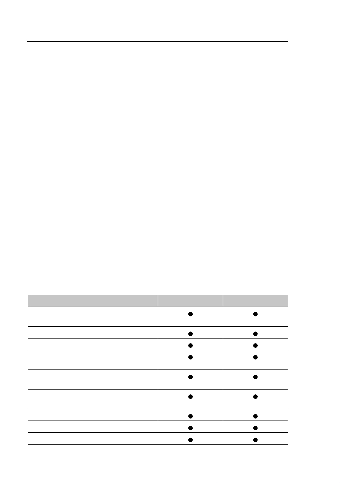
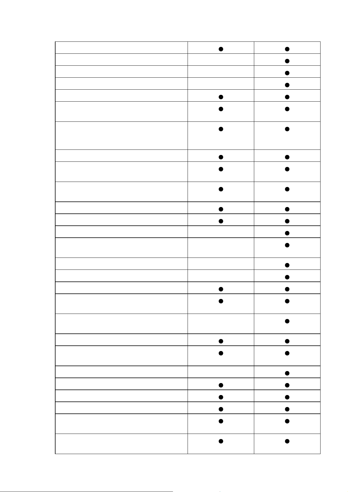
You can find an overview of the features and flexibility of the PERFECT 2030 and
the advanced model PERFECT 2040, in the following table.
Features Model 2030 Model 2040
Quartz-clock controlled and battery-
buffered real-time clock
Power reserve
Time, Day & Date Display
Automatic Daylight Savings Time
Adjustment
Automatic end-of-month date correction,
including leap years (perpetual calendar)
Automatic punch placement eliminates
over-punching
User defined time card format
Elapsed time printout
Time card total printout
2-2 Features Chapter 2
User defined punch rounding
User defined totals rounding
Day end moveable to next day
Day extend
User programmable two color printing
Large time card capacity (max. 250
active time card running totals)
Time card initialization (limits which
numbered time cards the time recorder
will accept)
User programmable date format
Individual card close-out with or without
carry forward of totals
Lost or mutilated time card replacement
(last cumulative total only)
Automatic switch-over from day to day
Forgotten punch monitoring
Overtime calculation
Fixed break / non-accumulating time
schedule
IN punch revisions
Lock out schedule
Programmable print formats
Automatic break deduction after
minimum presence time
Automatic variable break deduction after
scaleable minimum presence time
Duplicate punch protection
PIN-Code protection of programming
functions
Slave clock function (payable option)
Master clock function (payable option)
Time card reports
Protocol print out
Programmable audible signal circuit for
signaling stop and start work times
Available printer battery back-up
(payable option)
Chapter 2 Features 2-3
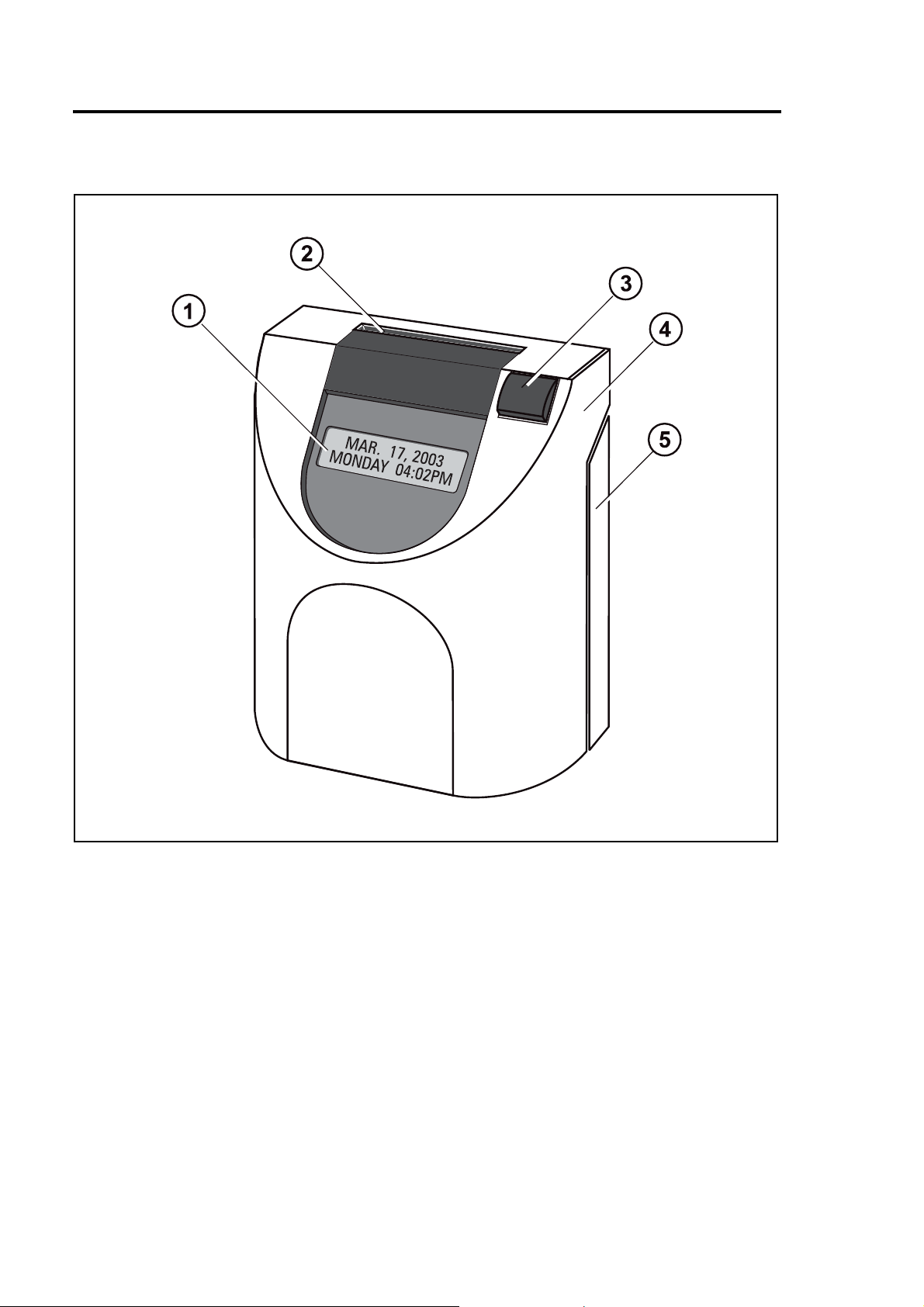
Recorder Construction
Fig. 1: Total view
(1) Display with day, date and time
(2) Card receiver
(3) Function key
(4) Removable front cover
(5) Rear cover
2-4 Features Chapter 2

Time Recorder Identification
• Electrical rating plate
• Program data
The name-plate is fixed on the bottom side of the cover.
The serial number is attached to the inside bottom of the unit.
Electrical data
The label with the program data (1) can be found on the operating system PROM of
the CPU.
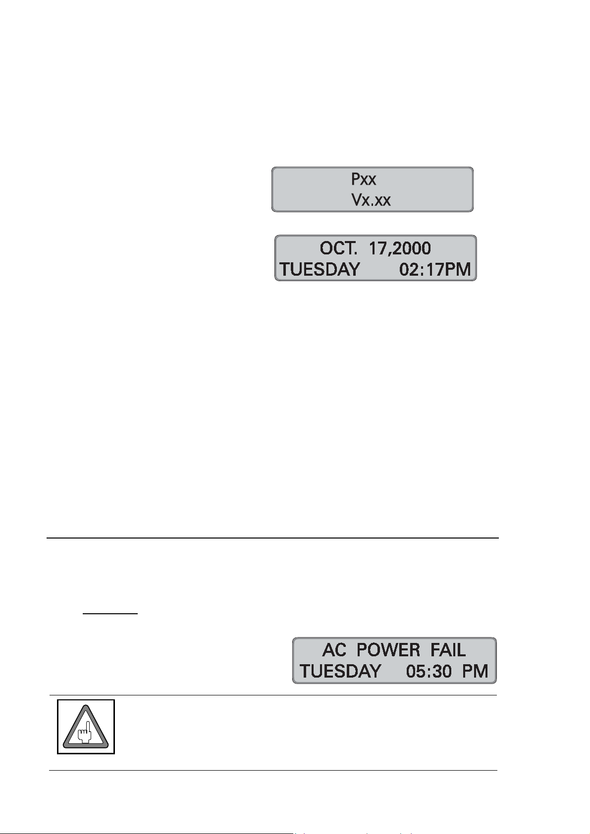
Example:
Type of recorder
P 2040 Type of recorder
V 2.20 Program release
Fig. 2: PC-Board
Chapter 2 Features 2-5

2-6 Features Chapter 2

Chapter 3
Installation
Contents............................................................................. 3-2
Selecting a Location ......................................................... 3-3
General Conditions............................................. 3-3
Specific Conditions for the Time Recorder......... 3-3
Time Recorder Installation............................................... 3-4
Installation for Table Operation............................... 3-4
Wall Mounting ........................................................... 3-5
Open the Recorder............................................. 3-6
Close the Recorder ............................................ 3-7
Remove the Metal Back Plate............................ 3-7
Wall Mounting .................................................... 3-8
Connect the Power Supply................................. 3-8
Connect Additional Functions............................. 3-10
Chapter 3 Installation 3-1
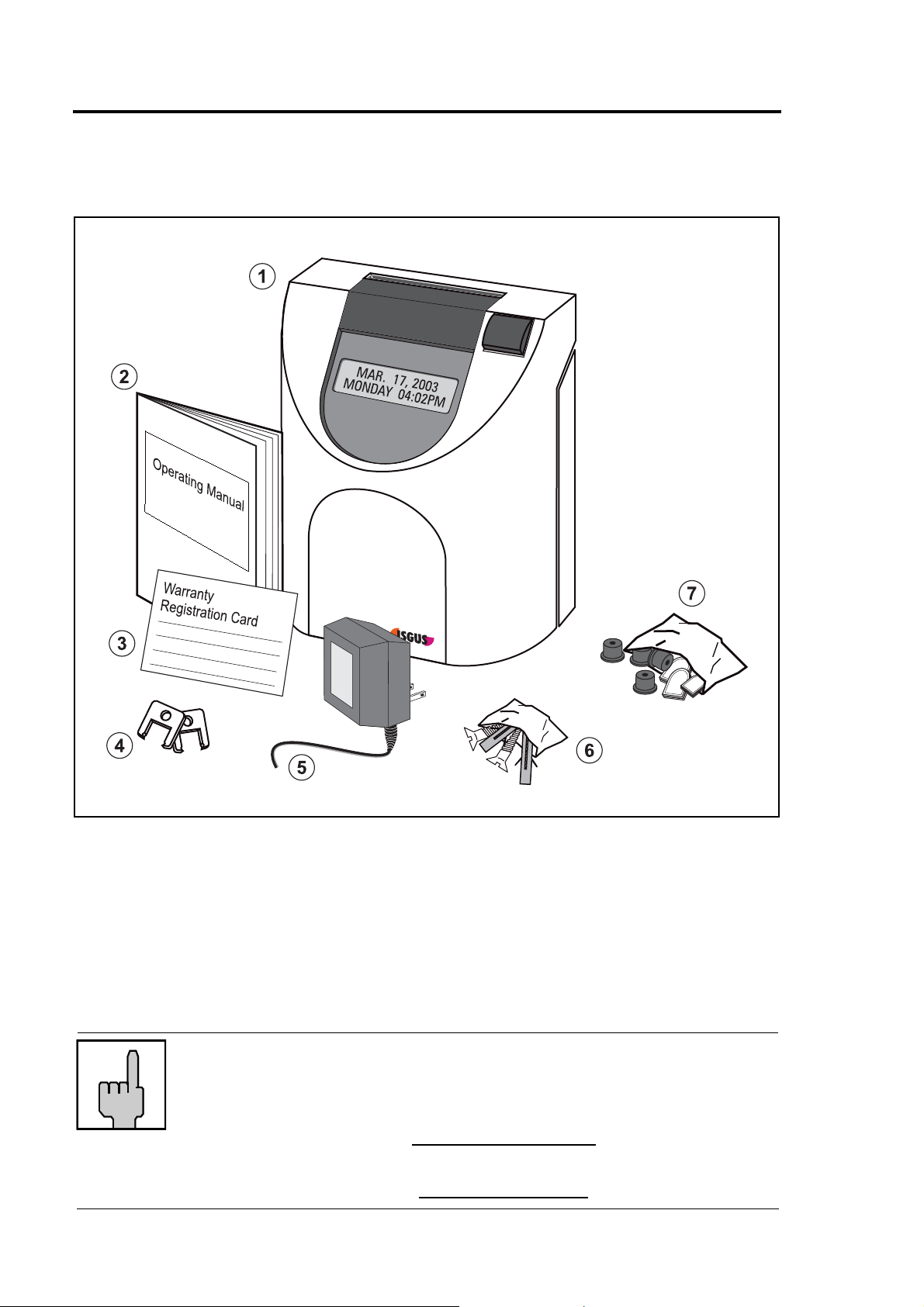
Contents
The following illustration shows the time recorder box contents without options.
Fig. 3: Supply
(1) Time recorder PERFECT 2040
(2) Operating manual
(3) Warranty Registration Card
(4) 2 keys
(5) Power supply unit
(6) Fixing elements for wall mounting (2 screws, 2 plugs)
(7) Set of accessories for table operation (4 rubber feet, 3 cover caps)
Hint
Time cards are not included with your time recorder and must be
ordered separately. Please contact your local dealer or e-mail us
at:
sales@ca.isgus.com
or
sales@isgus.com
3-2 Installation Chapter 3

Selecting a Location
Warning!
Proper installation of the time recorder is the responsibility of the
owner. All work must only be carried out by qualified personnel.
The installation must comply with the requirements of the
General Conditions
The installation location should have the following characteristics:
→ the time recorder is not exposed to electrical frequency transmissions
→ the time recorder is not exposed to direct sunlight.
→ the location’s environment is within the temperature and humidity limits
published in this manual.
authorities having jurisdiction and all applicable safety codes and
regulations that govern the installation of electrical appliances.
→ the location is free of airborne particles such as dust, dirt and fine powders
and there is no possibility of the time recorder being exposed to direct contact
with any kind of liquid or steam.
→ there are no dirty manufacturing processes that could contaminate the
location .
→ the location is isolated from electromagnetic noise sources such as motors,
electromagnets, and series reactors.
Specific Conditions for the Time Recorder
→ The time recorder is designed for continuous operation.
→ The time recorder is designed for indoor mounting only. Outdoor mounting is
not supported. Avoid direct sunlight and high humidity (refer to "Technical
Specifications, Appendix A".
→ Connection only to the mains voltage specified on the name-plate.
→ Cable connections must not be permanently installed.
→ Only use the recorder with the supplied power supply unit, both in table and
wall mount installations.
→ In the power supply installation in the building a separator, e.g. fuse, switch,
etc. must be integrated to allow a contact opening of at least 3 mm per pole.
→ Installation must be according to NEC requirements.
Chapter 3 Installation 3-3

Time Recorder Installation
Basically the PERFECT recorder is designed for table operation. No further settings
are required for this type of application. Please see the instructions in the following
section ”Installation for table operation”. If you have to connect additional functions
such as signal operation, master clock operation or standby operation refer to the
end of section "Wall mounting".
For wall mounting refer to the corresponding section "Wall mounting". When used as
wall-mounted recorder you have to carry out a number of installation steps described
in this chapter.
The connection of additional functions and the programming of the time recorder are
carried out with the time recorder’s case open. Below the time display panel you will
find a power switch and other electrical terminals and components. Please refer to
the section "Programming panel".
Warning!
All work must only be carried out by qualified and authorized
personal.
Installation for Table Operati on
When using the time recorder as a table model, the installation effort is reduced to a
minimum. Simply connect the power supply to the recorder and then plug it in to the
closest receptacle. Switch on the black power switch located on the PC board. For
instructions on how to switch the recorder on and how to program it for your
individual requirements see chapter "Getting Started".
Fig. 4: Bottom side of the recorder with rubber feet and mains cable s ocket
3-4 Installation Chapter 3
Select an easily accessible and vibration-free place of installation. The recorder may
only be placed on a stable, slip-resistant surface.
For the stability of the time recorder use the rubber feet included in the set of
accessories. For this purpose clip them on by following the arrow-head indications.
Also use the 3 cover caps for the metal back plate in order to seal the cable leadings.
The power outlet has to be close to the recorder and easily accessible. Lay the
power cable so that access is not obstructed and persons are not endangered.
Warning!
Only use the time recorder with the enclosed power supply both
in case of table operation and of wall mounting. Do not use
extension cords.
Wall Mounting
The PERFECT time recorder is designed for table mounting. However, power
connection and signal control terminals have been provided to meet the
requirements of eventual wall mounting applications.
Installation steps:
1. Open the time recorder
2. Remove the metal rear panel
3. Mount the time recorder on the wall
4. Connect the power supply
5. Connect any additional
functions (if required)
6. Commissioning
The location of the mounting holes
can be traced from the metal back
plate of the time recorder. The metal
back plate can be plugged in with the
plastic housing.
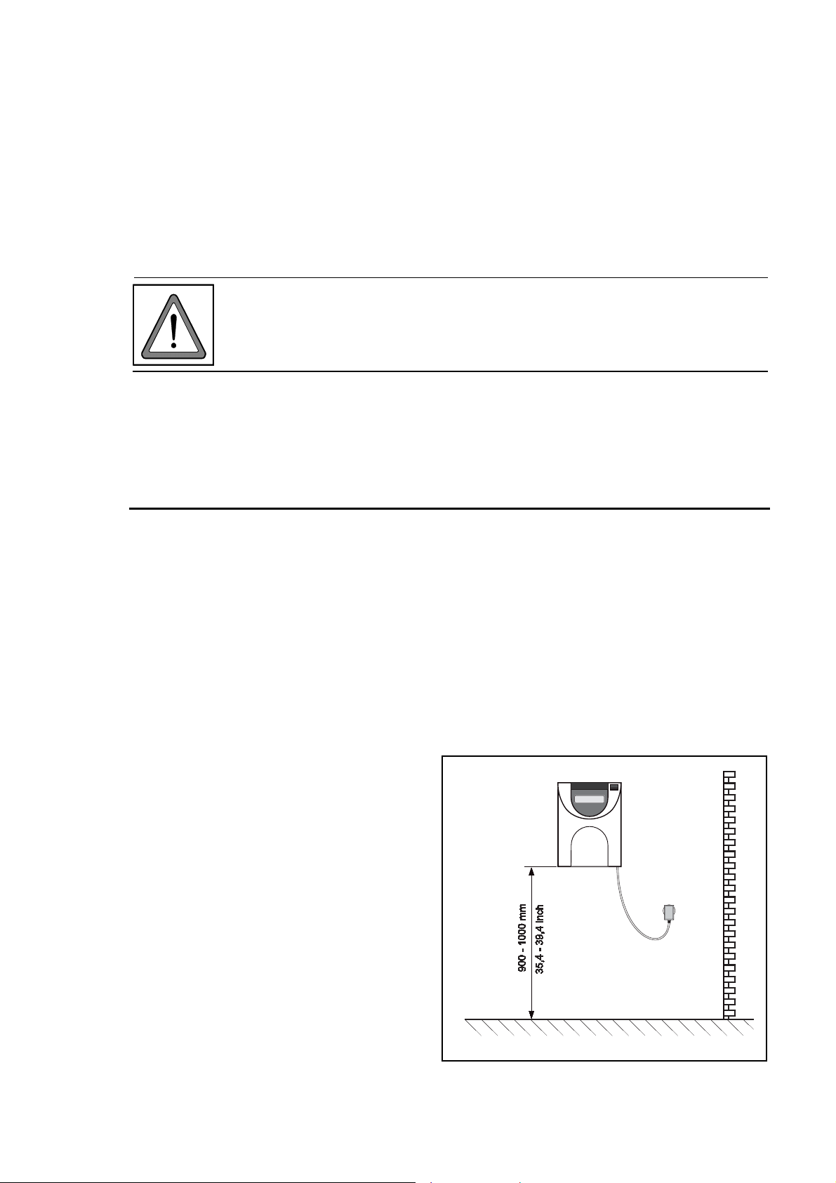
The installation dimensions shown in
the figure on the right are
recommendations which can be
adjusted to the local conditions. The
dimensions apply both for table
operation and for wall mounting.
Fig. 5: Installation dimensi ons
Chapter 3 Installation 3-5

Open the Recorder
1. Insert the key into the slot on the under side of the time recorder. Press the
key into the slot until the locking latch releases the front case cover.
Fig. 6: Unlock the recorder
2. Swing out the front case cover with the time recorder tilted away from you
(step 1) until it can be lifted up and off the time recorder (step 2).
Fig. 7: Open the recorder
3-6 Installation Chapter 3

Close the Recorder
1. Align and insert on an angle the two tabs at the top of the rear case cover into
the corresponding two slots at the top of the front case cover.
2. Swing the front case cover downwards until it meets the bottom of the rear
case cover. Push the bottom of the front case cover until it engages the
locking latch on the bottom of the rear case cover.
Hint
Do not close the time recorder until you have made all electrical
connections and completed all time recorder programming.
Remove the Metal Back Plate
1. To begin removing the metal back plate, press the two locking tabs located on
the top left and right hand sides of the rear case cover (step 1).
2. Keep the locking tabs pressed in and push the metal back plate back about ½
of an inch (step 2).
3. Pull the metal back plate away from the unit (step 3).
Fig. 8: Rear view of the rec order with metal back plate
Chapter 3 Installation 3-7

Wall Mounting
The location of the mounting holes can be traced from the metal back plate of the
time recorder. The metal back plate can be plugged in with the plastic housing.
See previous section. The installation dimensions mentioned in this manual are
recommendations which have to be adjusted for local conditions.
1. Position the metal back plate in the desired wall location. Make sure the back
plate is level by using a carpenter’s level
2. Using a pencil, trace the upper and lower mounting holes of the metal back
plate on the wall. Drill corresponding holes with a 5/16” drillbit . Insert the wall
plugs.
3. Mount the metal back plate starting first with the lower screw and then the top
screw. Make sure you do not fully tighten.
4. Using a carpenters level, align the time recorder once more and then tighten
both screws.
5. Hang the time recorder mechanism on the wall mounted metal back plate. The
four metal tabs (one on each corner of the metal back plate) must be aligned
and inserted into the corresponding slots of the rear case cover. When the
cover has been inserted correctly on the metal tabs, pull time recorder slightly
downwards until the locking mechanism engages.
Check your installation for good fits.
Connect the Power Supply
1. Make sure that the recorder has been switched off.
Fig. 9: PC-board with power switch
3-8 Installation Chapter 3

2. Check the connection of the power
cord to the screw-type terminal strip
of the CPU.
black
black
Attention
The power cord must be connected to the PC board
terminals that are electrically compatible with the supply
voltage of the electrical outlet that the power cord is plugged
into. Incorrect connections can cause the destruction of the
time recorder!
3. Connect the power cable of the power supply unit to the bottom side of your
PERFECT.
Fig. 10: Bottom side of the recorder with power cable socket
4. Insert the plug-in power supply unit into the provided socket.
Warning!
The power outlet must be close to the recorder and easily
accessible. Make sure, that a loose power cable does not
cause obstruction or risk to people.
Chapter 3 Installation 3-9

Connect Additional Functions
Only connect additional functions when they are required.
Additional functions:
− Signal operation
− Master clock operation (payable option)
− Slave clock operation (payable option)
− Standby operation (payable option)
All additional functions can be used for both types of installation, i.e. table or wall
mounted version.
When used as a table unit, the knockouts at the bottom of the metal rear back plate
have to be used for cable entry.
For wall mounted units the plastic knockouts on the bottom of the rear cover have to
be detached.
Attention
Units without the additional function "standby operation" only
operate with bridged standby clamp (Z-diode). See section
"Connection of battery pack" and chapter 6 "Trouble shooting".
Fig. 11: PC-board with additional functions
(1) Power connection terminals (2) Signal circuit connection terminals
(3) Master clock function (4) Battery, standby connector
(5) Slave clock function
Attention
Before installing additional functions switch off the unit and unplug
the power supply.
3-10 Installation Chapter 3

(2) Connect wiring for audible signal circuit control.
→ only if required.
→ low power signal output: 15V DC , 50 mA
3 4 5
NC - OUT +
Attention
This connection is polarity sensitive.
(3) Connect wiring for synchronized clock option
→ only if the recorder is equipped with the option module "MASTER CLOCK".
→ fused output rated at 12 V, max. 50 mA,
This connection is not polarity sensitive.
12
(4) Connect an optional battery pack for printer operation
during a power failure.
Attention
UL approval void if no approved batteries are installed!
1. Put the battery pack into the prepared battery
partition.
→ the battery partition is on the left side on the
bottom of the case.
2. Unplug bridge (Z-Diode, 12 V / 1 W) at clamp X5
of the PC board of the unit.
→ Hint: Keep the Z-Diode on hand.
The z-diode must be replaced, when removing
the battery pack.
3. Connect the cables of the battery pack to clamp
X5 of the PC board of the unit. + = red - = black
Attention
This connection is polarity sensitive.
Wrong connection causes a damage of the unit!
Chapter 3 Installation 3-11

(5) Connect impulse lines for slave clock connection.
→ Only if recorder is equipped with option module slave clock function/DCF"
→ unipolar and bipolar impulses, 12 V - 60 V, 2 - 10 mA.
This connection is not polarity sensitive.
12
The Installation is now finished.
To program the time recorder see chapter 4 "Getting Started".
If the recorder is to be programmed at a later date, insert the front cover and close
the recorder.
3-12 Installation Chapter 3

Chapter 4
Getting Started
Preparations...................................................................... 4-3
Open the Recorder............................................. 4-3
Powering Up The Time Recorder....................... 4-3
Powering Down the Time Recorder.................... 4-4
Programming Panel .......................................................... 4-5
Date / Time......................................................................... 4-7
Setting the Time only.......................................... 4-9
Set Time of Slave Clocks (optional)................... 4-10
Programming ..................................................................... 4-13
Calling up the Programming Routine
for the Main Programming Menu ........................ 4-14
Print Format .............................................................. 4-15
Punch Rounding....................................................... 4-19
Totals Rounding........................................................ 4-22
IN Punch Revisions .................................................. 4-25
Change or Delete Values for schedules
with IN Punch Revisions..................................... 4-31
OUT Punch Revisions .............................................. 4-32
Change or Delete Values for schedules
with OUT Punch Revisions................................. 4-38
Automatic Break....................................................... 4-39
Chapter 4 Getting Started 4-1

. continued
Fixed Break (Non Accumulation Times.................. 4-47
Change or Delete Values for Fixed Break
(no accumulation) Time Ranges........................ 4-52
Red Print (Ribbon Color Change)........................... 4-53
Change or Delete Values for Red Print /
Ribbon Color Changes....................................... 4-57
Overtime.................................................................... 4-58
Option Menu ............................................................. 4-63
Calling up the Programming Routine for
the Options Menu .............................................. 4-63
Daylight Savings Time............................................. 4-65
Deleting Cards.......................................................... 4-69
Maximum Presence .................................................. 4-70
Date Format .............................................................. 4-72
Day End..................................................................... 4-73
Day Extend................................................................ 4-75
Overtime 2................................................................. 4-77
Public Holidays......................................................... 4-82
Deleting Public Holidays.......................................... 4-84
Card Initialization ..................................................... 4-85
Duplicate Punch....................................................... 4-87
Reproducing Card.................................................... 4-88
Summary by Cards................................................... 4-88
Lock Out.................................................................... 4-89
Change or Delete Values for
Lock Out Schedules........................................... 4-93
Signal Operation....................................................... 4-94
Change or Delete Values for Signal Operation.. 4-98
Slave clock function................................................. 4-99
Master Clock Function............................................. 4-100
Synchronize the Slave Clocks ........................... 4-101
Card Validity Duration.............................................. 4-103
Quit Programming Mode ......................................... 4-105
Commissioning after Power Failure....................... 4-105
Service Call............................................................... 4-106
Print out of Program Settings ................................. 4-108
4-2 Getting Started Chapter 4
Preparations
Follow the instructions in this chapter and keep in the order the topics are presented.
Basic procedure and overview:
1. Open the recorder
2. Switch on recorder
3. Check date and time, and reset if necessary
4. Program the recorder
5. Close the recorder
6. Carry out test punches
Open the Recorder
If the recorder is not yet opened, remove the front cover as described in chapter 3,
"Installation".
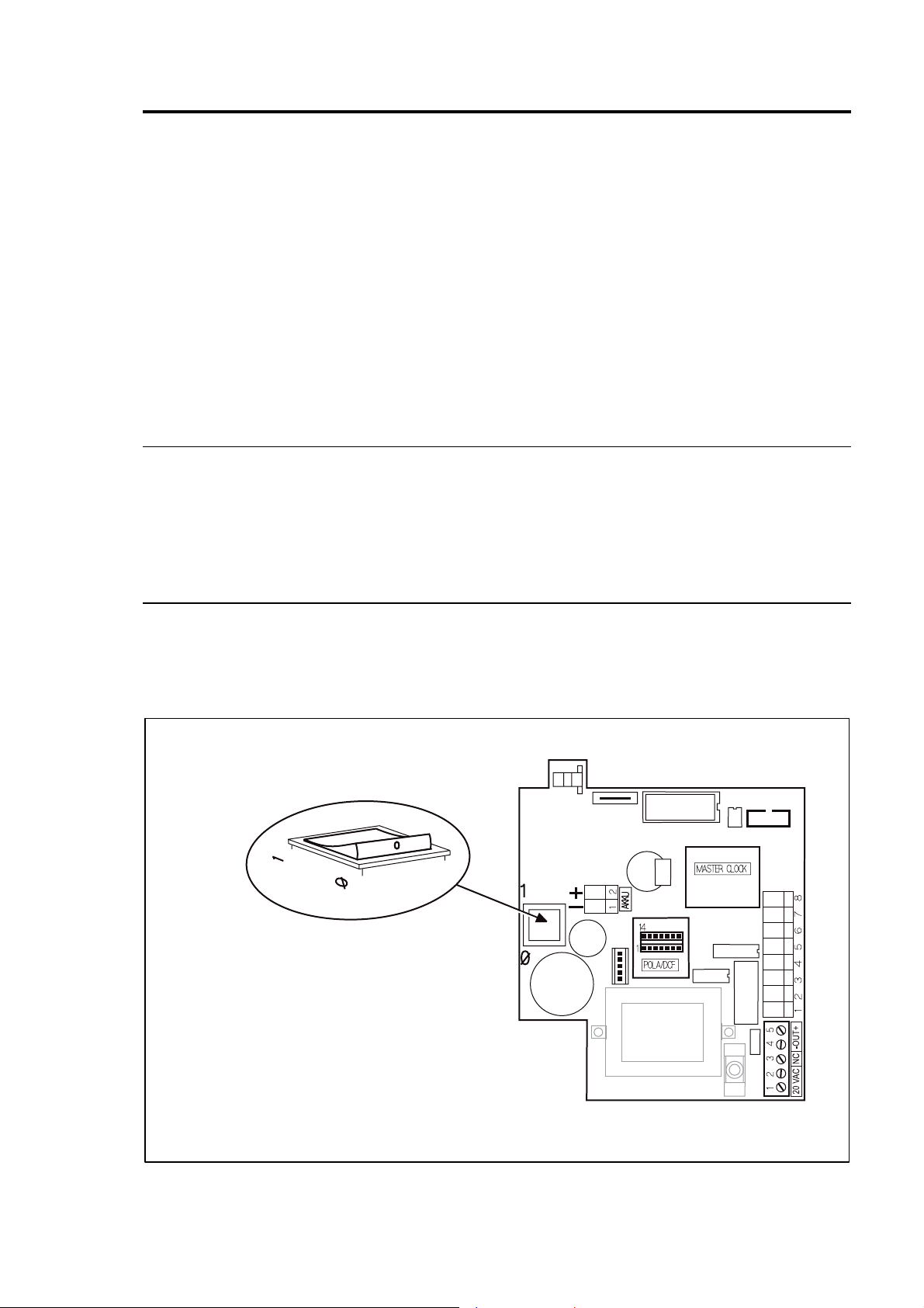
Powering Up The Time Recorder
The recorder is provided with a separate power switch. This power switch is located
inside the recorder, on the left hand side of the CPU-board.
Fig.12: PC-board with power switch
Chapter 4 Getting Started 4-3
Proceeding:
1. Make sure that the switch on the CPU board is in the off position (O).
2. Connect the time recorder’s power supply to the time recorder and then plug
the power supply into the closest AC power outlet.
3. Switch the power switch to position "1" (on).
→ Initialization is started
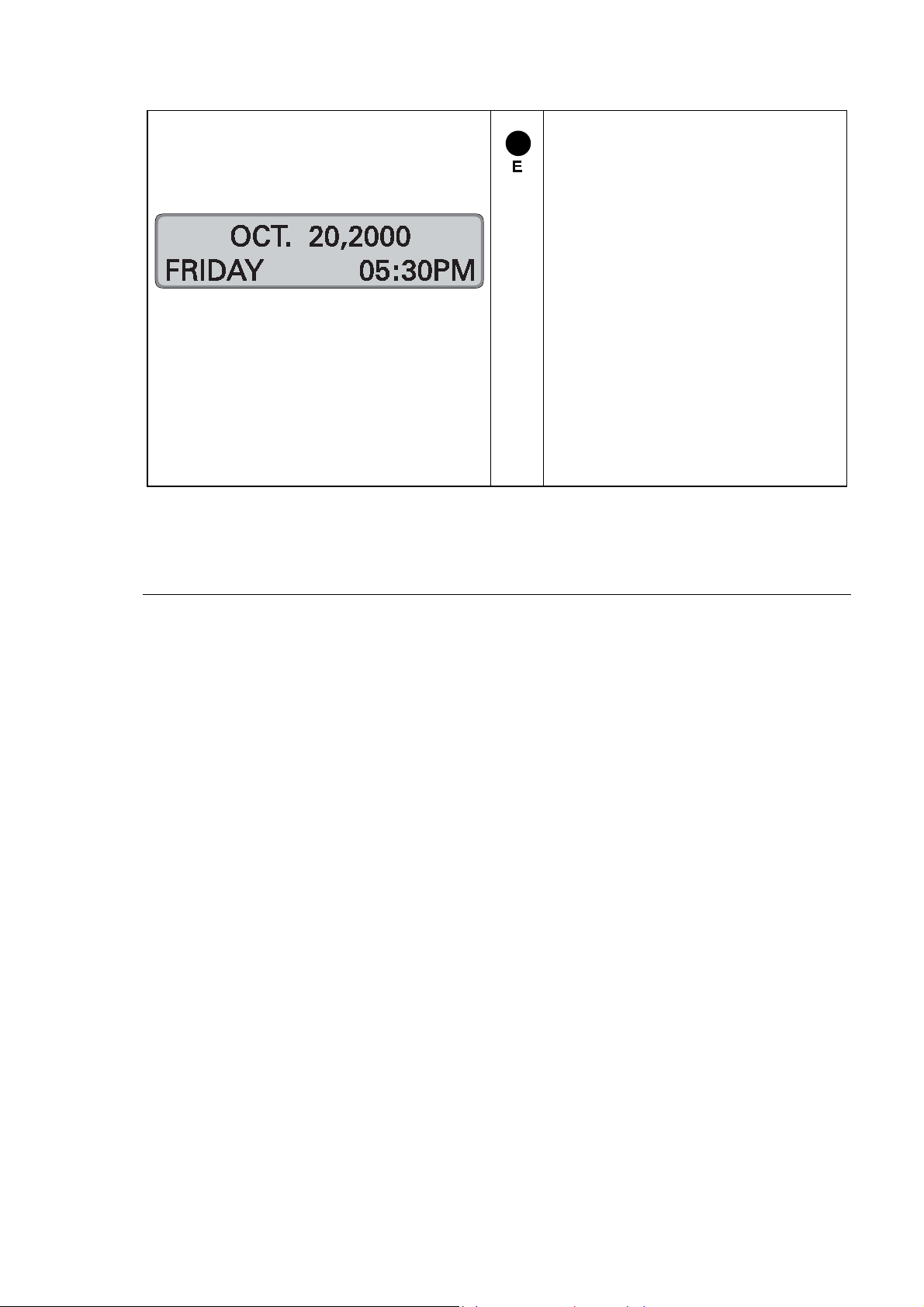
→ After a f ew seconds the
current date and time are
displayed.
Now the recorder is ready for operation. In some circumstances however, the
recorder may ask you to program the current time and date by displaying the
message "SET SYSTEM", and by flashing the hour digits.
→ For a detailed description of setting date and time, see "Time / Date" in
this chapter.
4. If the recorder has been programmed at our factory or by your dealer, close
the recorder by putting the front cover back on and locking it.
Now the recorder is ready for operation.
Familiarize yourself with the time recorder by punching a blank time card
several times. Additional information about using the time recorder is given in
chapter 5 "Punching at the Recorder“.
If the time recorder’s settings have not been previously programmed for your
application, you can now start to do so. Please refer to section "Programming"
in this chapter for a detailed description of programming procedures.
Powering Down the Time Recorder
1. Turn the time recorder off with the switch on the CPU board.
2. Observe the AC Power Fail message on the display.
3. Important
Wait a few seconds for the display to go blank.
4. Unplug the time recorder’s power
supply from the AC outlet.
Attention
Never plug or unplug the time recorder’s power supply with the
time recorder’s power switch in the On (1) position. This can
4-4 Getting Started Chapter 4
potentially create an electrical voltage spike that could damage
the time recorder’s CPU, which is not covered under warranty.
Programming Panel
For obvious security reasons, the time recorder’s programming panel is locked under
the front case cover and is not accessible to unauthorized users. To access the
panel, a user must have a key to unlock and remove the front cover.
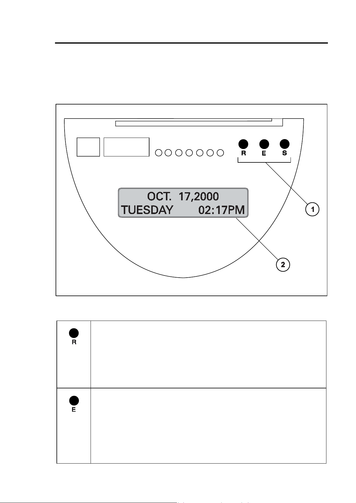
Fig. 13: Programming panel
(1) Programming keys R, E and S (2) Two-line display
Key R 〈Revise value〉
→ Activates the programming routine when continually pressed for more
than two seconds.
→ Pressing the key once changes flashing displayed values in single
increments.
→ Keeping the key pressed changes displayed flashing values quickly
by scrolling through possible selections in a fast mode.
Key E 〈Enter〉
→ Activates the date and time setting routine.
→ When in the programming mode or in the time and date setting
mode, it enters into memory the values that the user selected with
the "R“ key. The display then switches to the next value in the current
programming field or to the next programming field. By repeated
pressing of the "E" key it is possible to scroll through and view
existing program settings.
Chapter 4 Getting Started 4-5

Key S 〈Skip〉
→ In the programming mode this key serves to sequentially skip from
the current programming field to the next field. However, for the "S“
key to perform this function, the user must have programmed all
values in the current field.
→ In the normal operating mode, this key serves to delete cards from
the time recorder’s memory (if the function Card Close Out is
enables)
Program display
→ Line 1 = program field
→ Line 2. = program value
The flashing character(s) is the
active value being programmed.
4-6 Getting Started Chapter 4
Date / Time
The recorder is provided with a battery-buffered quartz clock with power reserve. The
lithium battery stores the correct time for years in case of power failure.
Setting of date and time is usually necessary only during commissioning of the
recorder.
The exact display of the current date is guaranteed by an integrated “eternal
calendar“.
The PERFECT 2040 can be operated in two different time modes.
- 12 hour range with use of the AM/PM abbreviation for morning/afternoon
- 24 hour range from 0.00 to 24.00 hours.
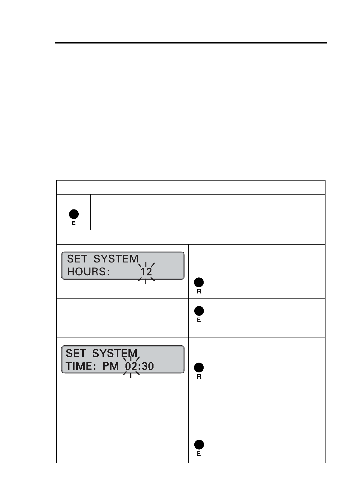
Calling up the setting routine
The recorder is switched on.
Press "E" (approx. 2 seconds) until display switches to "SET
SYSTEM".
Settings
The time mode has to be
determined before date and time
are set.
= Set the desired mode.
Range of values: 12 or 24
= Confirm setting.
Recorder changes to entry of
time.
Setting the time
Format: HH:MM
= Set desired hour
Range of values: 00 - 12
or 00 - 24
Hint: If the 12 hour time mode
is selected, a change from AM
to PM is to be achieved by
scrolling the hour value.
= Confirm setting.
Recorder changes to minutes.
Chapter 4 Getting Started 4-7
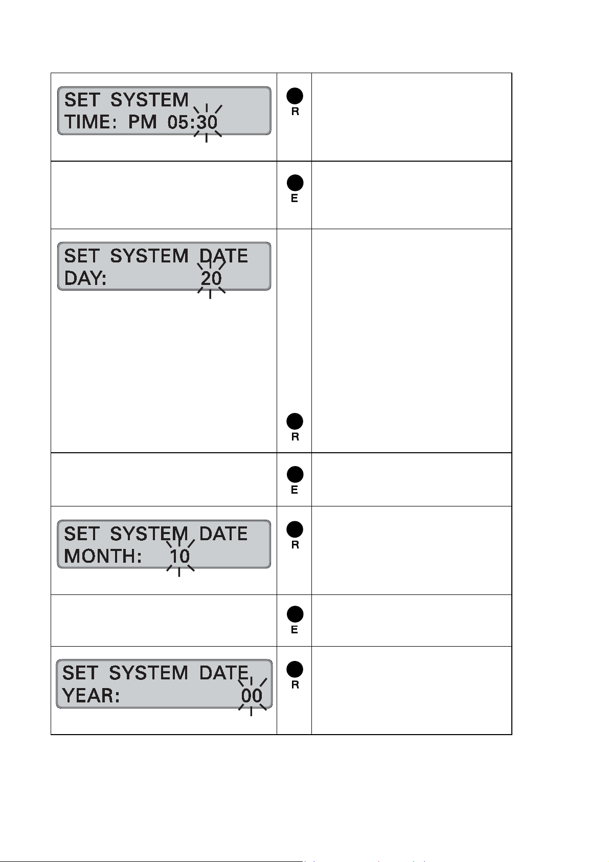
= Enter the desired minutes
Range of values: 00 - 59
Note: By keeping this key
pressed the value is scrolled.
= Confirm setting.
Recorder changes to date
input.
Date entry
Entry format: DD MM YY
The steps for setting the date are
divided into day, month, year.
Hint: The entry order does not
effect the display's date format
in normal operation mode.
First setting is the day
Range of values: 01 - 31
= Enter the desired day.
= Confirm setting.
Recorder changes to month.
= Set desired month.
Range of values: 01 - 12
Hint: By keeping this key
pressed the value is scrolled.
= Confirm setting.
Recorder changes to year.
= Set desired year.
Range of values: 00 - 99
Note: By keeping this key
pressed the value is scrolled.
4-8 Getting Started Chapter 4
= Confirm the selection, setting
routine is completed.
The recorder changes to
operating display and shows
the current date and time.
Hint: If the "Master Clock"
option is enabled in the
function programming, the
time recorder will immediate ly
begin to transmit minute
impulses to connected slave
clocks. Refer to the
programming instructions "
"Setting time of slave clocks".
Setting the Time only
After setting the time, you can skip setting the date (if not required), by pressing the
"E" key until the recorder returns to its normal operating mode display.
Conversely, if you only want to set the date and do not wish to change the time, you
can jump ahead to the date entry fields by pressing the "S" key just once.
Chapter 4 Getting Started 4-9

Set Time of Slave Clocks (optional)
Hint
The following procedure is only performed when slave clocks are
connected to the time recorder. The default setting from the
"Slave clocks“ are clocks whose time is controlled by a "master clock“. These clocks
can be other time recorders or wall clocks mounted in common work areas such as
lunch rooms and offices. Configuring a master / slave clock system benefits users by
establishing one "official“ workplace time and by providing automatic resetting of
connected time devices after power failures or after Daylight Savings Time changes.
factory is to disable this option, therefore this routine should not
be done until after the initial start-up of the time recorder.
For further details please contact your local dealer where you
have purchased the time recorder or e-mail us at:
support@ca.isgus.com
or
techsupport@isgus.com
A master / slave clock system of synchronized workplace time has the following
pre-requisites:
• The "Master Clock“ hardware and software options have been installed in the
PERFECT time recorder.
• The "Slave Clock“ hardware and software options have been installed in those
time recorders designated as slave clocks.
• A 12“ diameter, 12 volt ISGUS system wall clock has been installed in those
locations (locker rooms, offices etc.) designated to be slave clocks.
• All slave clock locations have been wired and connected back to this time
recorder’s (the master clock) location with two #14 AWG copper conductors.
• All installation work must be performed and verified by qualified staff.
Proceed as follows:
1. Ensure that the hardware and installation prerequisites previously listed
have been met.
2. Check or set time and date for this recorder.
3. Carry out the complete programming routine of the time recorder.
→ By enabling the function "Master Clock" this recorder is defined
as a master clock.
4. Re-enter the "Set time and date“ program mode for this time recorder.
5. Follow the steps of the below sequence. A distinction is made between
slave clocks with:
− Straight Polarity operation
− Reverse Polarity operation
As to the operating mode of your slave clocks please refer to the
manufacturers specifications
4-10 Getting Started Chapter 4

Slave clock synchronization with unipolar activation
= Call up the set time and date
routine.
! Confirm time of master clock
with "S" and date with "E"
! If it is necessary to change
time and/or date of master
clock, see previous
instructions " setting routine
time and date"
! After having confirmed the
year with "E" the recorder
changes to slave clock
synchronization.
Set the slave clocks manually to
the same time
Set the slave clock time on the
master clock.
= Set the value.
= Confirm settings, continue with
Time setting, see previous
instructions
Slave clock synchronization with bipolar activation
= Call up the set time and date
! Confirm time of master clock
1. value = hours,
2. value = minutes
next value
routine.
with "S" and date with "E"
! If it is necessary to change
time and/or date of master
clock, see previous
instructions " setting routine
time and date"
Chapter 4 Getting Started 4-11

! After having confirmed the
year with "E" the recorder
changes to slave clock
synchronization.
Set slave clocks manually to the
same time
Hint: This display only appears
when the setting "Reverse Pola"
has been selected in the
parameter "Master Clock".
= Transmit single impulses to
the slave clocks.
1 = positive impulses
0 = negative impulses
Positive / negative impulse
selection alternates with each
key actuation.
Make sure that with each
impulse, all slave clocks advance
at even resp. odd numbered
minutes.
! Reverse the polarity
connection of the slave clocks
that do not advance
When all slave clocks advance in
After completing the entry by pressing "E" the slave clocks are set automatically to
the current time of the master clock.
The automatic resetting of the slave clock may take several minutes, after which the
time recorder returns immediately to the normal operating mode. Punching time
cards, at the time recorder is possible during slave clock synchronization.
unison, confirm the process with
"E".
Set the slave clock time on the
master clock.
= Set the value.
1. value = hours,
2. value = minutes
= Confirm settings, continue with
next value
Time setting, see previous
proceeding.
4-12 Getting Started Chapter 4

Programming
The programming of the PERFECT is made in 2 menus:
- Main Programming Menu
- Options Menu
Each menu is divided into menu items, which must be programmed in chronological
order. For each item, the current programming field is described on the first line of
the time recorder’s display.
Unless it is mandatory, a programming field can be skipped by pressing the "S“ key.
If you do not wish to change a value, simply press the "E“ key and you will advance
to the next field without changing that value.
Hint
The values used on the next pages are only examples and may
differ from your values.
To ensure system integrity, access to the programming mode is protected by a 4 digit
numeric PIN code. An initial PIN is assigned to this PIN code ex factory.
If an incorrect PIN code is entered, the time recorder automatically exits the
programming mode.
In the examples, the 12 hour time mode is always used.
The factory set initial PIN code is : 0 0 0 0
Attention
Extreme caution is advised. It is recommended to replace the
factory-set initial PIN code with your own individual number.
However, if you forget your unique PIN code, you will have to
return the time recorder to ISGUS for reprogramming.
Chapter 4 Getting Started 4-13

Calling up the Programming Routine for the Main Programming Menu
To call up the programming routine for the main programming menu, the front cover
of the recorder must be removed. If the recorder is switched off, you must switch it
on with the mains switch. Refer to section "Switch on recorder".
Calling up the programming routine
→ Recorder is switched on.
Press "R" (at least 2 seconds) until display switches to
"ENT.EXISTING PIN".
PIN-code input
Each PIN-code input is started with the
display of a 4-digit zero. The first digit
flashes.
For the first calling up and if the
PIN Code is not changed
the initial PIN = 0000
The entry of the code-number
begins with the left flashing digit.
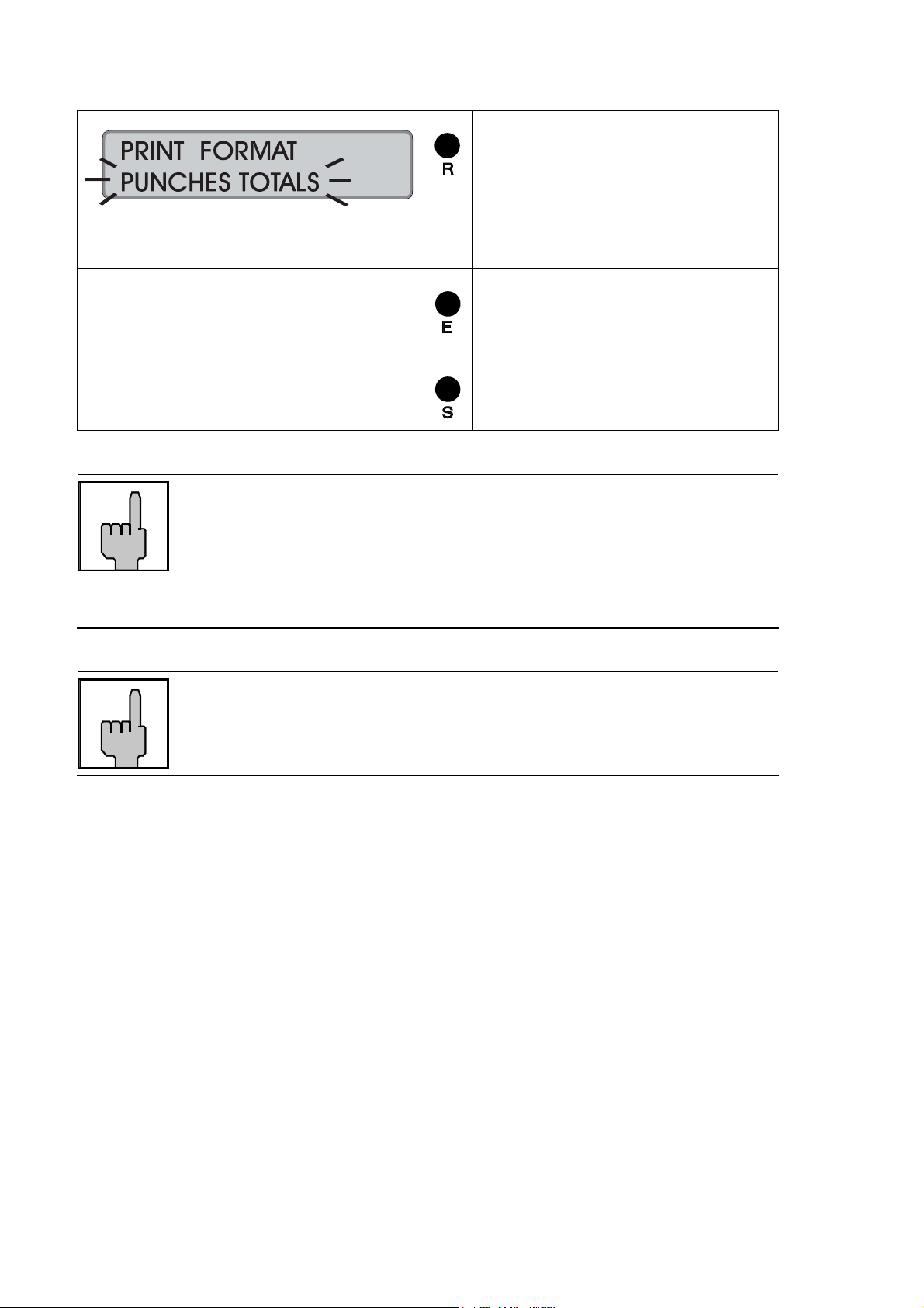
If initial PIN is kept
The recorder continues with
function "PRINT FORMAT".
If individual PIN is entered
= enter each digit and
= confirm each digit
Recorder changes to next input
digit.
After having confirmed the last
digit with key "E" the recorder
continues with function "PRINT
FORMAT".
4-14 Getting Started Chapter 4

Print Format
Print formats determine how and where
"IN" punches, "OUT" punches, and various
combinations of hour totals are printed on
the time card.
With the aid of this function you can select
in addition the minutes printing format.
Format
No.
1
2
3
4
5
6
7
8
9
10
11
12
13
Column 1 Column 2 Column 3 Column 4 Column 5 Column 6 Column 7 Column 8 Column
Date IN time OUT time Interval
Date IN time OUT time Interval
Date IN time OUT time Card
Date IN time OUT time IN time OUT time
Date IN time OUT time Interval
Date IN time OUT time Interval
Date IN time OUT time Card
Date IN time OUT time
Date IN time OUT time Reg Hrs
Date IN time OUT time Reg Hrs
Date IN time OUT time Reg Hrs
Date IN time OUT time Reg Hrs
Date IN time OUT time Reg Hrs
Card example
Total
Total
Total
Total
Interval
Total
Card
Total
Interval
Total
Interval
Total
Interval
Total
9
Card
Total
IN time OUT time Interval
Total
Card
Total
Total
OT Hrs
Interval
Total
OT Hrs
Card
Total
OT 1+ 2
Hrs
Interval
Total
OT 1 Hrs
Interval
Total
OT Hrs
Interval
Total
IN time OUT time Interval
Total
Total
IN time OUT time Card
Reg Hrs
Card
Total
IN Time Out Time Reg Hrs
Card
Total
Reg Hrs
Card
Total
OT 2 Hrs
Interval
Total
Reg Hrs
Card
Total
Reg Hrs
Card
Total
OT Hrs
Card
Total
OT 1 Hrs
Card
Total
OT 1 Hrs
Card
Total
Card
Total
Total
OT Hrs
Card
Total
OT Hrs
Card
Total
OT 2 Hrs
Card
Total
OT 2 Hrs
Card
Total
Chapter 4 Getting Started 4-15

Hint
With the unit you can use one of 2 possible standard card types.
The cards differ by their card width. The print formats 1 to 3 and
Formats 1-8
In columns 4 and 8 the clocking difference between IN and OUT punchings is
determined and printed.
In columns 5 and 9 the cumulative totals of the presence time are shown.
The totals are added until a new card without total carryover is used or the card is
deleted in the recorder.
Format 9
The normal time is printed out in column 4 and the ov er time i s pri nted out i n column 5.
The total from column 4 and column 5 produces the presence time.
Column 8 shows the cumulative total of normal time.
Column 9 shows the cumulative total of overtime.
The totals are added until a new card without total carryover is used or the card is
deleted in the recorder.
Format 10
The cumulative total values of normal time are printed out in columns 4 and 8.
9 to 12 are not suited for the small card type.
In columns 5 and 9 the cumulative totals of overtime are shown.
The totals are added until a new card without total carryover is used or the card is
deleted in the recorder.
Format 11
The normal time is printed out in column 4 and the ov erti me of account 1 and
account 2. is printed out in col umn 5. The total from column 4 and column 5 produces
the presence time.
Column 7 shows the cumulative total of normal time.
Column 8 shows the cumulative total of overtime account 1
Column 9 shows the cumulative total of overtime account 2
The totals are added until a new card without total carryover is used or the card is
deleted in the recorder.
Format 12
The cumulative total values of normal time are printed out in columns 4 and 7.
In columns 5 and 8 the cumulative totals of overtime account 1 are shown.
In columns 6 and 9 the cumulative totals of overtime account 2 are shown.
The totals are added until a new card without total carryover is used or the card is
deleted in the recorder.
4-16 Getting Started Chapter 4

Format 13
The normal time is printed out in column 4 and the ov er time i s pri nted out i n column 5.
The total from column 4 and column 5 produces the presence time.
Column 6 shows the cumulative total of normal time.
Column 7 shows the cumulative total of overtime.
The totals are added until a new card without total carryover is used or the card is
deleted in the recorder.
Hint
In order to be able to better understand how differences and
totals are determined and for reasons of clarity, we recommend
Factory setting: → Format 09 or 13 and
print format for minutes = 1/60 hours.
not to change the print format as long as printing is being carried
out on the same card.
Proceeding
= Select print format
or
= Confirm setting
= Print format for minutes
Range of values:
01MIN = 1/60 h
15MIN = 1/4 h
10THS = 1/10 h
100THS = 1/100 h
= Confirm selection and continue
with next parameter.
Hint! If 10THS or 100THS is
selected for the minutes
printout, the unit switches to
the next input level.
Chapter 4 Getting Started 4-17
= Select range of validity for
Hint
If 10THS or 100THS is selected as the format for the minutes
printout, a * is displayed to the right of the current time on the
display, e.g. Monday 07.49 A*.
A conversion table for the individual minute print formats is to be
found in Annex D.
or
minute printing format.
Range of values: Totals,
Punches
+ Totals
= Confirm selection and continue
with next parameter.
Hint
Differences and totals are always calculated in hours and
minutes, but they are always printed out in hours and the
selected minute print format.
4-18 Getting Started Chapter 4

Punch Rounding
The PERFECT has the ability to round "In“ and "Out“ punches either forwards or
backwards depending on company defined qualification periods.
The first step in programming punch rounding is to establish the time intervals that
the time recorder will divide work hours into. We call these "time accounting units“.
The available time accounting units are: 2, 3, 5, 6, 10, 12, 15, 20 and 30 minutes.
Additionally, rounding qualifications can be determined separately for IN and OUT
punchings. The rounding qualification can be set and defines in which case a
punching is rounded up or down. These qualifications are called "Late IN" for IN
punchings and "Early OUT" for OUT punchings.
For IN punchings, the qualification always begins with the beginning of the interval.
For OUT punchings, the qualification is always considered retroactively from the end
of the interval.
If punchings are within the qualification, the recorder always rounds in favour of the
employee. That is to say, for IN punchings the recorder rounds down , for OUT
punchings the recorder rounds up.
If punchings are beyond the qualification or if they are equal to the qualification
value, the recorder always rounds not in favour of the employee. That is to say, for
IN punchings the recorder rounds up, for OUT punchings the recorder rounds down.
Example:
Rounding interval = Accounting Unit 15 minutes
Rounding qualification IN = Late IN 7 minutes
Rounding qualification OUT = Early OUT 10 minutes
Punching Time Rounded
IN 7:45 7:45
IN 7:51 7:45
IN 7:52 8:00
IN 8:00 8:00
OUT 11:45 11:45
OUT 11:50 11:45
OUT 11:51 12:00
OUT 12:00 12:00
In addition, it is possible to define whether the rounded or the not rounded original
time is to be printed on the time card.
Chapter 4 Getting Started 4-19
not rounded original punching time is printed
Date IN
(printed)
IN
(rounded and
not printed)
OUT
(printed)
OUT
(rounded and
not printed)
03.12.00 AM 7:51 AM 7:45 AM 11:50 AM 11:45 4.00
04.12.00 AM 7:52 AM 8:00 AM 11:51 PM 12:00 8.00
rounded punching time is printed
Date IN
(not printed)
IN
(rounded and
printed)
OUT
(not printed)
OUT
(rounded and
printed)
03.12.00 AM 7:51 AM 7:45 AM 11:50 AM 11:45 4.00
04.12.00 AM 7:52 AM 8:00 AM 11:51 PM 12:00 8.00
Hint
When determining the punching differences and the totals, the
recorder in both cases calculates with the rounded IN and OUT
punches.
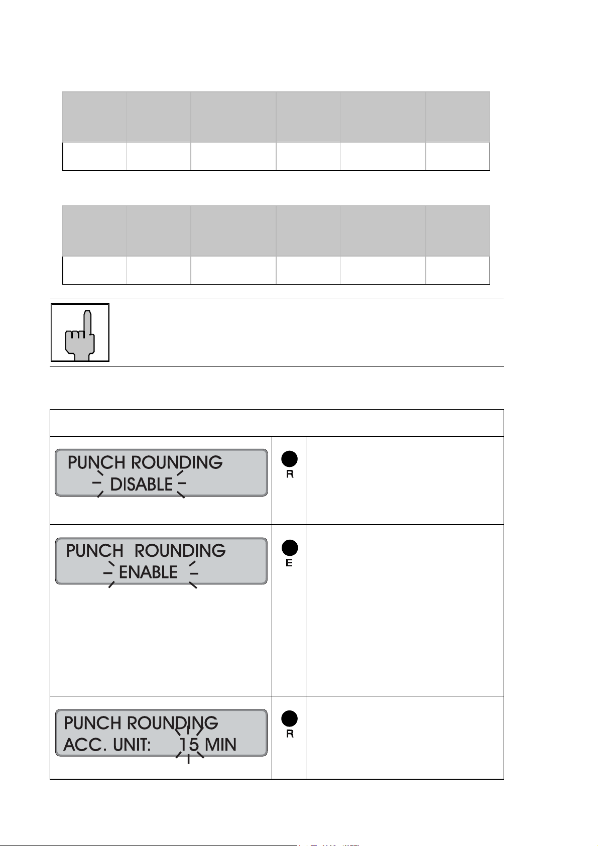
Factory setting: → function deactivated
Total
Total
Proceeding
= Activate the function.
Or:
Switch to the next parameter
with "S".
= Confirm setting.
Recorder changes to the input
level.
1st setting = Rounding
interval
2nd setting = Rounding
qualification IN
3rd setting = Rounding
qualification
OUT
= Set rounding interval.
The intervals are fix and
defined in steps of 2, 3, 5, 6,
10, 12, 15, 20 and 30 minutes.
4-20 Getting Started Chapter 4

= Confirm selection.
= Set rounding qualification for
IN punching.
Range of values: 00 - 29 min.
Hint: By keeping this key
pressed the value is scrolled.
= Confirm selection.
= Set rounding qualification for
OUT punching.
Range of values: 0 - 29 min.
Note: By keeping this key
pressed the value is scrolled.
= Confirm selection.
Recorder changes to next
input level.
= Select time to be printed on
the card:
Range of values:
unrounded,
rounded.
= Confirm selection and return to
menu level.
= Continue with next parameter.
Hint: Use "E" to return to the
input level.
Hint
In order to be able to better understand how differences and
totals are determined and for reasons of clarity, we recommend
setting only one type of rounding in the recorder, either PUNCH
ROUNDING or TOTALS ROUNDING.
Chapter 4 Getting Started 4-21

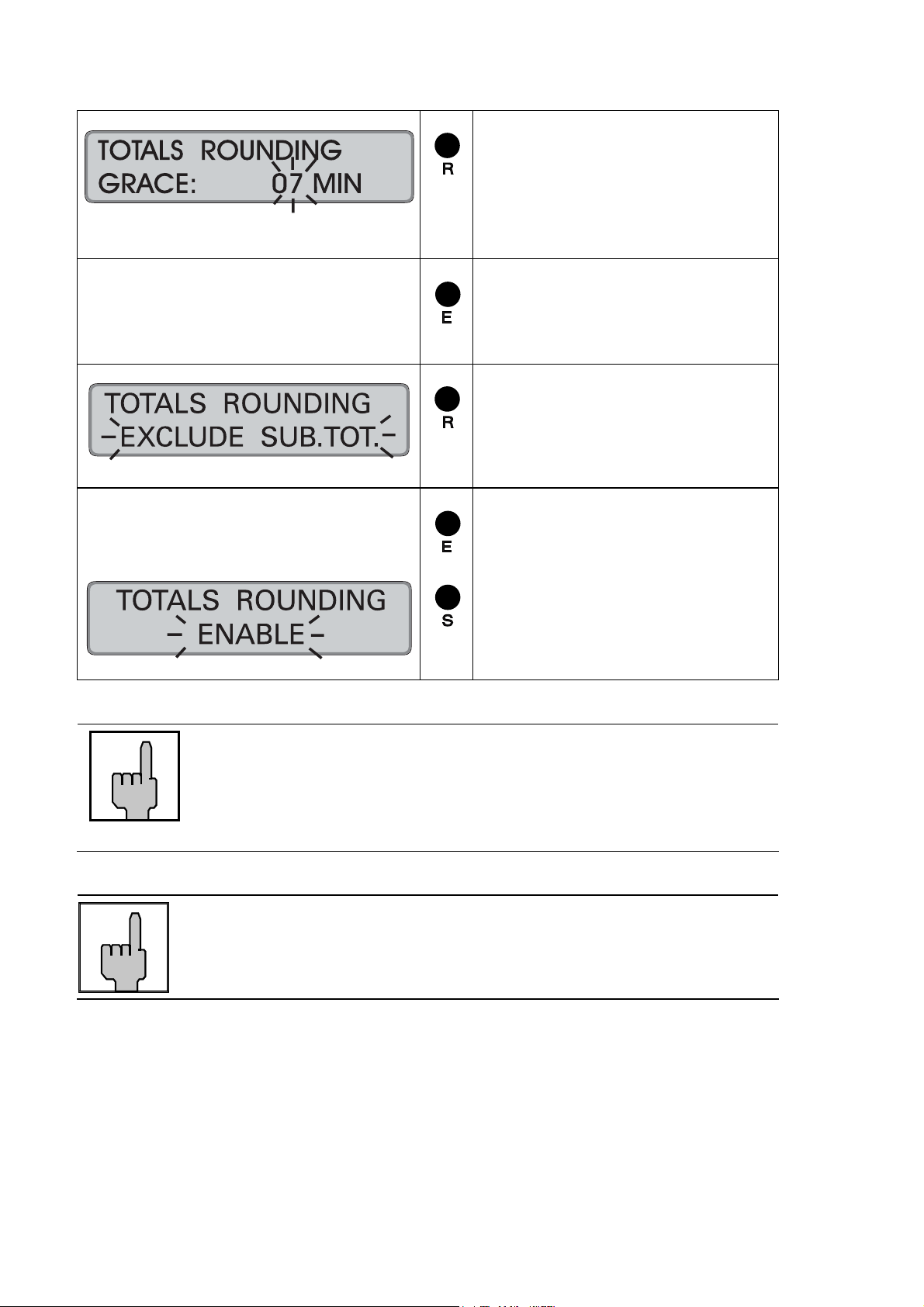
Totals Rounding
The recorder has a rounding function for results.
The intervals that the time recorder will divide work hours into are called "time
accounting units".
The time accounting units (rounding intervals) can be selected in steps of:
2, 3, 5, 6, 10, 12, 15, 20 and 30 minutes.
In addition a rounding qualification can be created. The rounding qualification can be
set and defines in which case a punching is rounded up or down.
The qualification is always regarded retroactively from the end of the interval.
If results are within the qualification, the recorder always rounds in favour of the
employee i.e. it rounds up.
If results are beyond the qualification or if they are equal to the qualification value,
the recorder always rounds not in favour of the employee, i.e. it rounds down.
Depending on the setting, the recorder rounds either totals (= exclude sub-totals) or
differences (= include sub-totals).
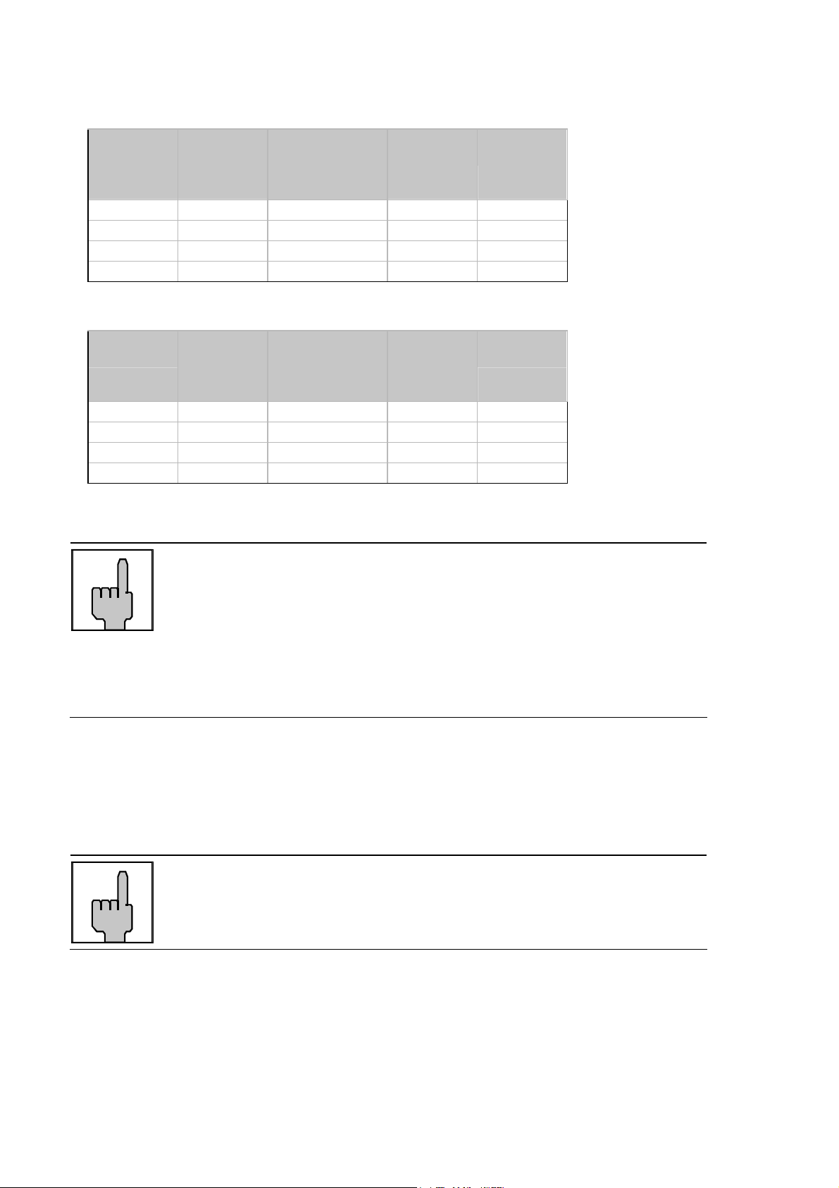
Examples
Rounding interval = Accounting Unit 15 minutes
Rounding qualification = Grace setting 7 minutes
Example 1 Rounding totals (= exclude sub-totals)
Date IN OUT Difference
(printed)
Total
(not printed)
01.12.00 AM 7:00 AM 11:08 4.08 4.08 4.00
01.12.00 PM 1:00 PM 5:16 4.16 8.24 8.30
02.12.00 AM 7:00 AM 11:15 4.15 12.39 12.45
02.12.00 PM 1:00 PM 5:14 4.14 16.53 16.45
Hint
With this setting the totals are determined by first adding the
differences and then rounding them.
4-22 Getting Started Chapter 4
Total
(rounded and
printed)
Example 2 Rounding differences (= include sub-totals)
Date IN OUT Difference
(not printed)
Difference
(rounded and
printed)
01.12.00 AM 7:00 AM 11:08 4.08 4.00 4.00
01.12.00 PM 1:00 PM 5:16 4.16 4.15 8.15
02.12.00 AM 7:00 AM 11:15 4.15 4.15 12.30
02.12.00 PM 1:00 PM 5:14 4.14 4.15 16.45
Hint
With this setting the totals are determined by first rounding the
differences and then adding them.
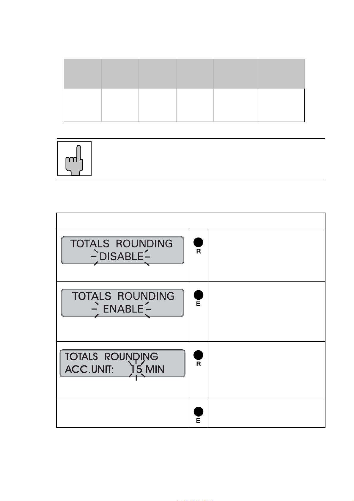
Factory setting: → function deactivated
Proceeding
= Activate the function.
Total
(printed)
Or:
Switch to the next parameter
with "S".
= Confirm setting.
Recorder changes to the input
level.
st
setting = R interval
1
nd
2
setting = R qualification
= Set rounding interval.
The intervals are fix and
defined in steps of 2, 3, 5, 6,
10, 12, 15, 20 and 30 minutes.
= Confirm selection.
Chapter 4 Getting Started 4-23
= Set rounding qualification.
Range of values: 00 -14 min.
Hint: By keeping this key
pressed the value is scrolled.
= Confirm selection.
Recorder changes to input
level.
= Select function.
Selection:
- EXCLUDE SUB.TOT
- INCLUDE SUB.TOT
= Confirm selection and return to
menu level.
= Continue with next parameter.
Hint: Use "E" to return to the
input level.
Hint
In order to be able to better understand how differences and
totals are determined and for reasons of clarity, we recommend
setting only one type of rounding in the recorder, either PUNCH
ROUNDING or TOTALS ROUNDING.
Hint
If, in addition, the OVERTIME function is activated, also the
rounded values for overtime totals are printed.
4-24 Getting Started Chapter 4

IN Punch Revisions
It is possible to set 4 time ranges per weekday within which the first IN punch of the
employees is rounded.
The definition of such revision time ranges makes it possible to
- round the first IN punch of an employee to the start of working time
e.g. for shifts
Additionally, it is possible to determine a rounding qualification, which is valid for all
revision time ranges of the week.
The qualification value (grace) is always considered retroactively from the end of the
interval.
Within the defined revision time range the first IN punch is rounded to the rounding
time. The rounding time results from revision time range end minus grace.
Punches at revision time range start are rounded to the rounding time,
punches at the revision time range end are not rounded.
Example A: Revision time range: from = AM 07:30 to = AM 08:07
Grace: 07 minutes
Rounding time: = revision time range end minus grace
= AM 08:07 - 00:07 = AM 08:00
Punching Time Rounded
IN AM 7:30 AM 8:00
IN AM 8:01 AM 8:00
IN AM 8:06 AM 8:00
IN AM 8:07 AM 8:07
In addition, it is possible to define whether the rounded or the not rounded original
time is to be printed on the time card.
Hint
When determining the punching differences and the totals, the
recorder calculates with the rounded IN punches.
Chapter 4 Getting Started 4-25
not rounded original punching time is printed
Date IN
(printed)
IN
(rounded and
not printed)
OUT
25.11.02 AM 7:30 AM 8:00 PM 12:00 4.00
26.11.02 AM 8:01 AM 8:00 PM 12:00 8.00
27.11.02 AM 8:06 AM 8:00 PM 12:00 12.00
28.11.02 AM 8:07 AM 8:07 PM 12:00 15:53
rounded punching time is printed
Date IN
(not printed)
IN
(rounded and
printed)
OUT
25.11.02 AM 7:30 AM 8:00 PM 12:00 4.00
26.11.02 AM 8:01 AM 8:00 PM 12:00 8.00
27.11.02 AM 8:06 AM 8:00 PM 12:00 12.00
28.11.02 AM 8:07 AM 8:07 PM 12:00 15:53
Total
Total
Hint
In order to use this function for punch pairs, where the first IN
punch is rounded up to a time after the date change, the IN
punch revision schedule must also be defined beyond the date
change.
In the input routine possible time settings for the following day
are automatically marked with "+" in the 12 hours mode as well
as in the 24 hours mode (see the following example)
Example B: Revision time range on Monday: from = PM 11:30 to = AM + 00:22
Grace: 07 minutes
Rounding time: = revision time range end minus grace
= AM + 00:22 - 00.07 = AM + 00:15
Hint
If IN punches on Tuesday in the revision time range AM 00:00 to
AM 00:22 should be rounded to AM 00:15, it is necessary to
enter a corresponding time schedule for Tuesday.
Factory setting: → function deactivated
4-26 Getting Started Chapter 4
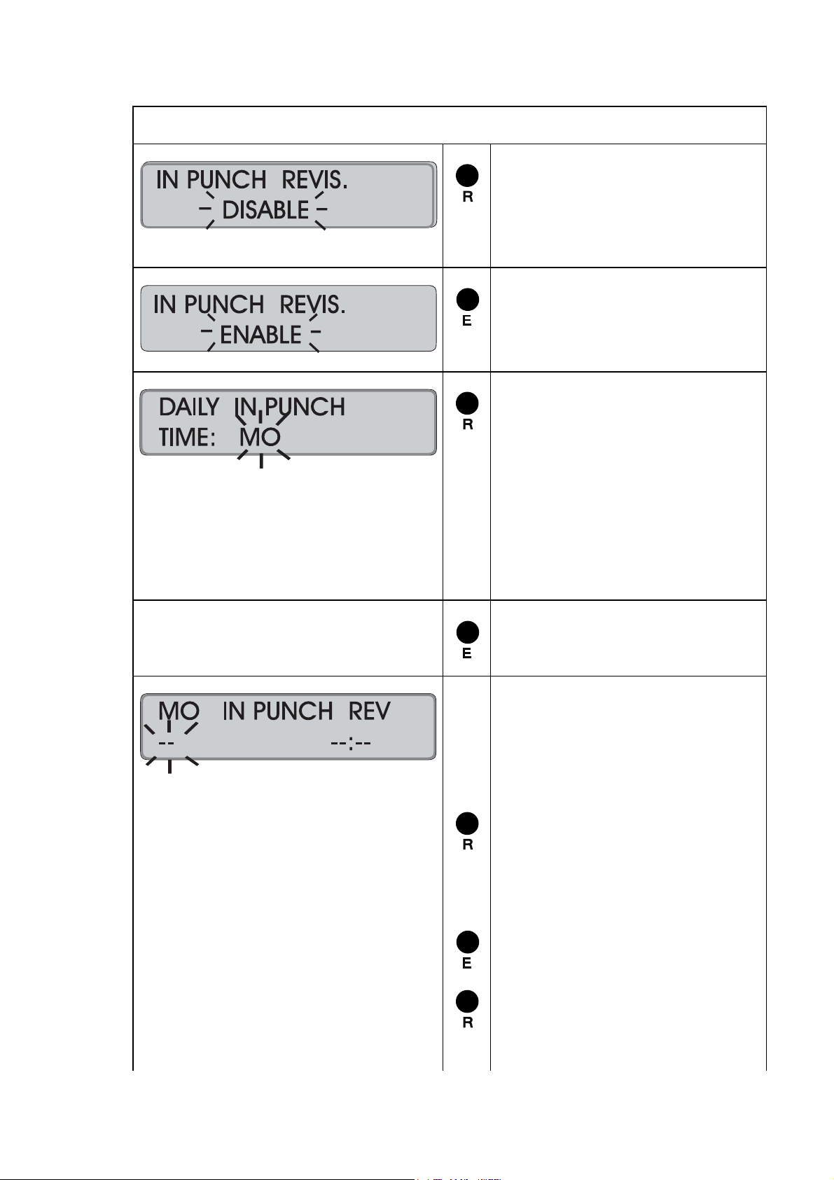
Proceeding
= Activate the function
Or:
Switch to the next parameter
with "S".
= Confirm setting
Recorder changes to the next
input level.
= Select the day of the week to
program the IN punch revision
schedule.
Range of values: MO to SU
Example: MO;
It is also possible to start on
any other weekday.
Note: By keeping this key
pressed the value is scrolled.
= Confirm selection.
1st input field = Start or
end of the
range with
IN punch
revision
2nd input field = time value =
= Select function of the first input
field.
Range of values: FROM, TO,
−−,
= Confirm 1st input field
= Set the related time value in
the second input field.
Format: : hours, minutes
Chapter 4 Getting Started 4-27

Hint: If the 12 hour time mode
is selected, a change from AM
to PM is to be achieved by
scrolling the hour value.
Possible time indications for
the following day are
automatically marked with "+"
in the 12 hours mode as well
as in the 24 hours mode.
= Confirm 2nd input field.
The values are stored and the
display is emptied, the first
input field flashes again.
Repeat this procedure for further
IN punch revision schedules for
this weekday.
= Return to the previous input
level when you have entered
all schedules with IN punch
revision for this weekday.
Select a new day if ranges with
IN punch revision differ from the
already defined weekday.
Proceed as described above.
Or:
= Switch over to the copying
function.
Copying function
1st input field = "copy from"
2nd input field = "copy to"
= Select the "copy from" day.
4-28 Getting Started Chapter 4
= Confirm 1st input field.

= Select the "copy to" day(or
days)
Hint: With this f unction you
can copy the defined values
directly to consecutive
weekdays. All you do is select
the last consecutive weekday
instead of just the next
weekday, e.g. Friday instead of
Tuesday.
= Confirm 2nd input field.
Repeat the copying process if
further schedules with IN punch
revision shall be copied to other
weekdays.
= Switch over to next input level,
when you have copied all
schedules with IN punch
revision.
= Set rounding qualification for
first IN punching.
Range of values: 0 - 59 min.
Note: By keeping this key
pressed the value is scrolled.
= Confirm selection.
Recorder changes to next
input level.
= Select time to be printed on
the card:
Range of values:
rounded,
unrounded.
Chapter 4 Getting Started 4-29
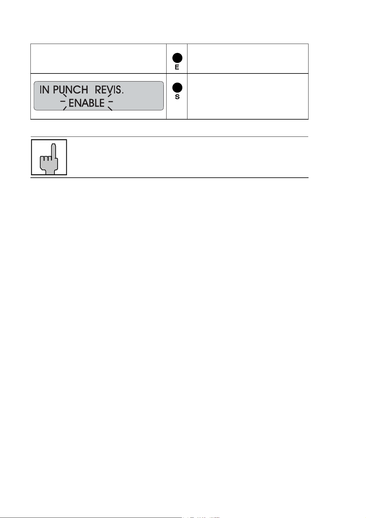
Hint
If, in addition, the PUNCH ROUNDING function is activated, the
recorder ignores the settings of the PUNCH ROUNDING function
during an IN punch revision time range.
= Confirm selection and return to
menu level.
= Continue with next parameter.
Hint: Use "E" to return to the
input level.
4-30 Getting Started Chapter 4

Change or Delete Values for schedules with IN Punch Revisions
The IN Punch Revision schedules can be modified at any time. Use the copy
function in order to change or delete several days at a time.
Procedure:
1. Call-up the programming routine. ("R" key)
2. Select the "IN Punch Revision" menu ("S" key)
3. Select the weekday on which changes
are to be made. ("R" key)
4. Call up the time value to be changed. (Click through with "E" key)
5. Change the beginning or end of the schedule ("R" and "E" keys)
with IN Punch Revision / or change the time value
If you want to delete the displayed time value,
set the 1st input field "Beginning /end of the schedule with
IN punch revision" to "− −"
and confirm with "E".
The 2nd input field "Time value" is then deleted
and the next value is displayed.
→ To make further changes for this weekday,
repeat steps 4 and 5.
6. Complete settings for this weekday: ("S" key)
→ In order to make changes for other weekdays,
repeat steps 3 to 6 or:
7. Skip to "Copy function" to
copy the changed weekday to further weekdays. ("S" key)
8. Select the "day range“ which the
changed day schedule will be copied to. ("R" and "E" key)
9. Quit copying function and skip to. ("S" key)
next input level "enter grace"
10. Change qualification value ("R" and "E" key)
11. Switch over to next input level ("S" key)
"printed time"
12. Select form of printed time ("R" and "E" key)
13. Quit the "IN Punch Revision" menu ("S" key)
14. Quit the programming routine (continue with "S" key)
→ Date and time are displayed.
Chapter 4 Getting Started 4-31
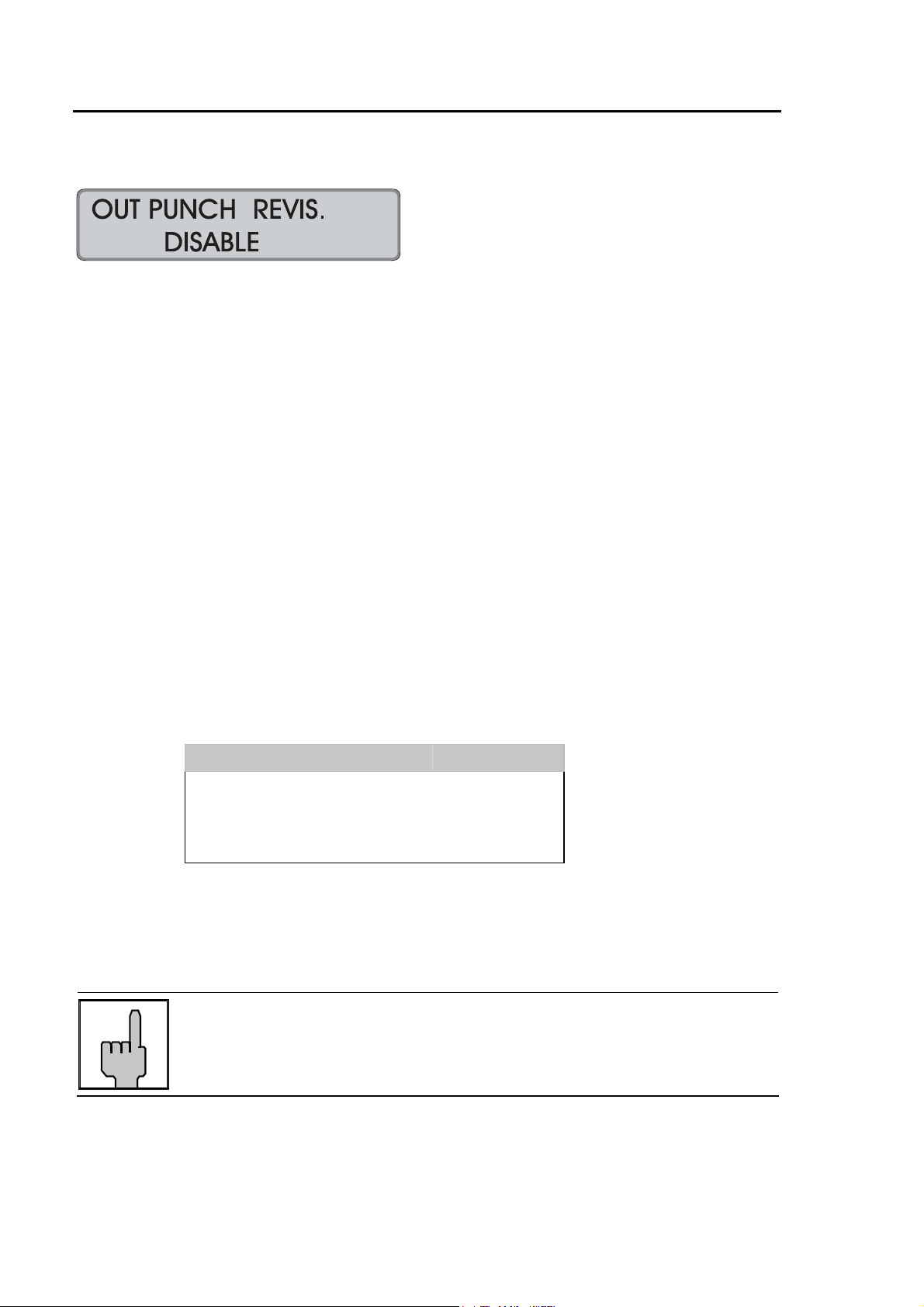
OUT Punch Revisions
It is possible to set 4 time ranges per weekday within which the OUT punch of the
employees is rounded.
The definition of such time ranges makes it possible to
- round the OUT punch of an employee to the end of working time
e.g. for shifts
Additionally, it is possible to determine a rounding qualification (grace), which is valid
for all time ranges of the week.
If the total of punching time plus grace is < revision time range start, the punches are
not rounded.
If the total of punching time plus grace is = or > revision time range start, the
punches are rounded to the revision time range start.
Example A: Revision time range: from = PM 05:00 to = PM 06:00
Grace: 15 minutes
Punching Time Rounded
OUT PM 04:44 PM 04:44
OUT PM 04:45 PM 05:00
OUT PM 05:10 PM 05:00
OUT PM 05:30 PM 05:00
In addition, it is possible to define whether the rounded or the not rounded original
time is to be printed on the time card.
Hint
When determining the punching differences and the totals, the
recorder calculates with the rounded OUT punches.
4-32 Getting Started Chapter 4

not rounded original punching time is printed
Date IN OUT
(printed)
OUT
(rounded and
not printed)
25.11.02 PM 01:00 PM 04:44 PM 04:44 3.44
26.11.02 PM 01:00 PM 04:45 PM 05:00 7.44
27.11.02 PM 01:00 PM 05:10 PM 05:00 11.44
28.11.02 PM 01:00 PM 05:30 PM 05:00 15.44
rounded punching time is printed
Date IN OUT
(not printed)
OUT
(rounded and
printed)
25.11.02 PM 01:00 PM 04:44 PM 04:44 3.44
26.11.02 PM 01:00 PM 04:45 PM 05:00 7.44
27.11.02 PM 01:00 PM 05:10 PM 05:00 11.44
28.11.02 PM 01:00 PM 05:30 PM 05:00 15.44
Total
Total
Hint
In order to use this function for punch pairs, where the OUT
punch is rounded up to a time after the date change, the OUT
punch revision schedule must also be defined beyond the date
change.
In the input routine possible time settings for the following day
are automatically marked with "+" in the 12 hours mode as well
as in the 24 hours mode (see the following example)
Example B: Revision time range on Monday: from = AM + 02:00 to = AM + 03:00
Grace: 15 minutes
Hint
If OUT punches should be rounded on Tuesday during the
revision time range from AM 02:00 to AM 03:00, it is necessary
to enter a corresponding time schedule for Tuesday.
Factory setting: → function deactivated
Chapter 4 Getting Started 4-33
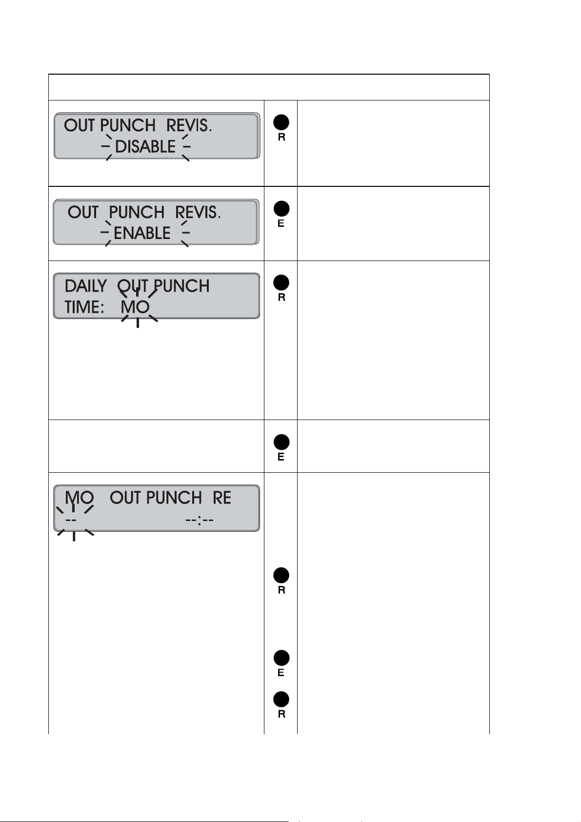
Proceeding
= Activate the function
Or:
Switch to the next parameter
with "S".
= Confirm setting
Recorder changes to the next
input level.
= Select the day of the week to
program the OUT punch
revision schedule.
Range of values: MO to SU
Example: MO;
It is also possible to start on
any other weekday.
Note: By keeping this key
pressed the value is scrolled.
= Confirm selection.
1st input field = Start or
end of the
OUT punch
revision range
2nd input field = time value =
= Select function of the first input
field.
Range of values: FROM, TO,
−−,
= Confirm 1st input field
= Set the related time value in
the second input field.
Format: : hours, minutes
4-34 Getting Started Chapter 4
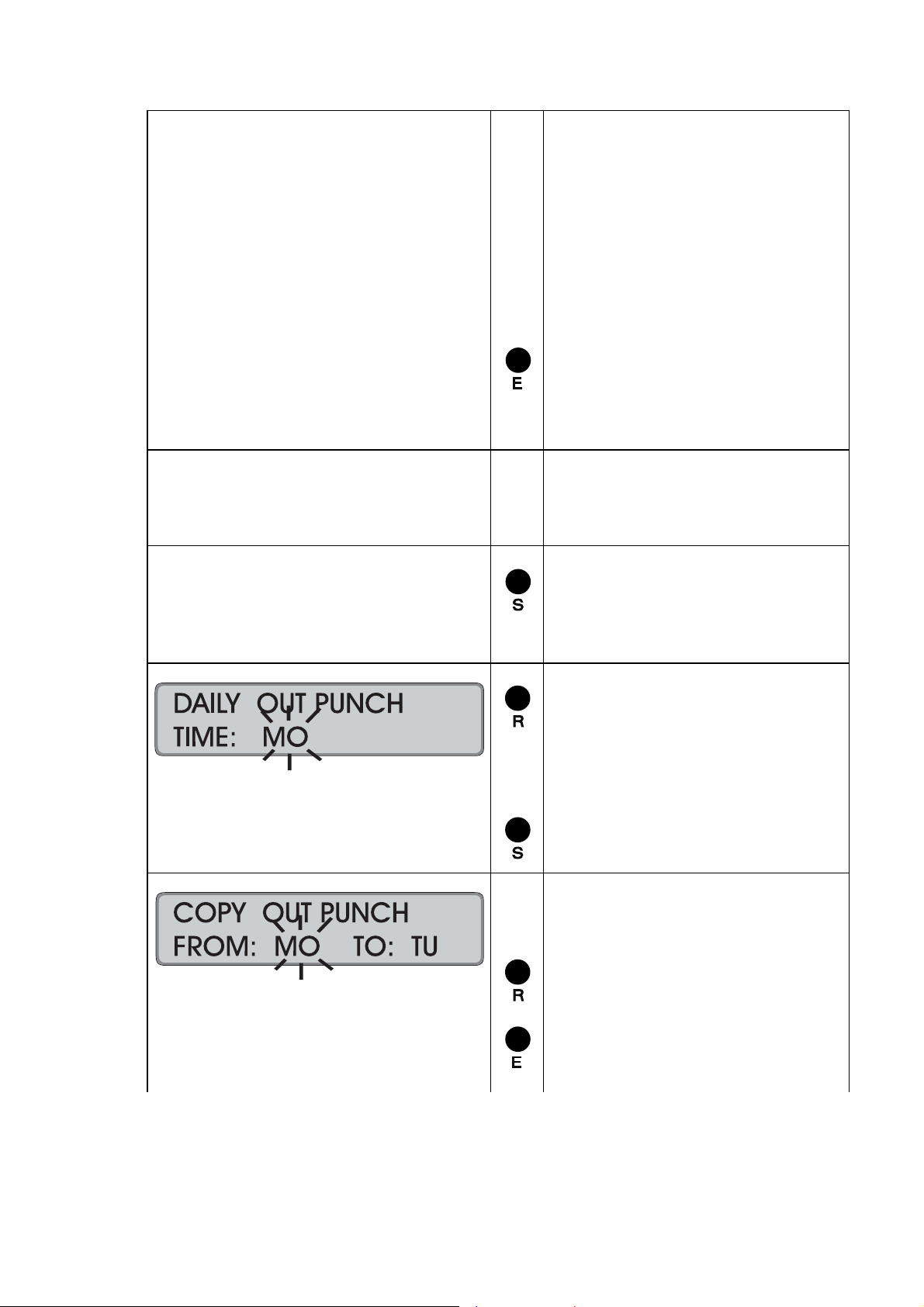
Hint: If the 12 hour time mode
is selected, a change from AM
to PM is to be achieved by
scrolling the hour value.
Possible time indications for
the following day are
automatically marked with "+"
in the 12 hours mode as well
as in the 24 hours mode.
= Confirm 2nd input field.
The values are stored and the
display is emptied, the first
input field flashes again.
Repeat this procedure for further
OUT punch revision schedules
for this weekday.
= Return to the previous input
level when you have entered
all schedules with OUT punch
revision for this weekday.
Select a new day if ranges with
OUT punch revision differ from
the already defined weekday.
Proceed as described above.
Or:
= Switch over to the copying
function.
Copying function
1st input field = "copy from"
2nd input field = "copy to"
= Select the "copy from" day.
Chapter 4 Getting Started 4-35
= Confirm 1st input field.
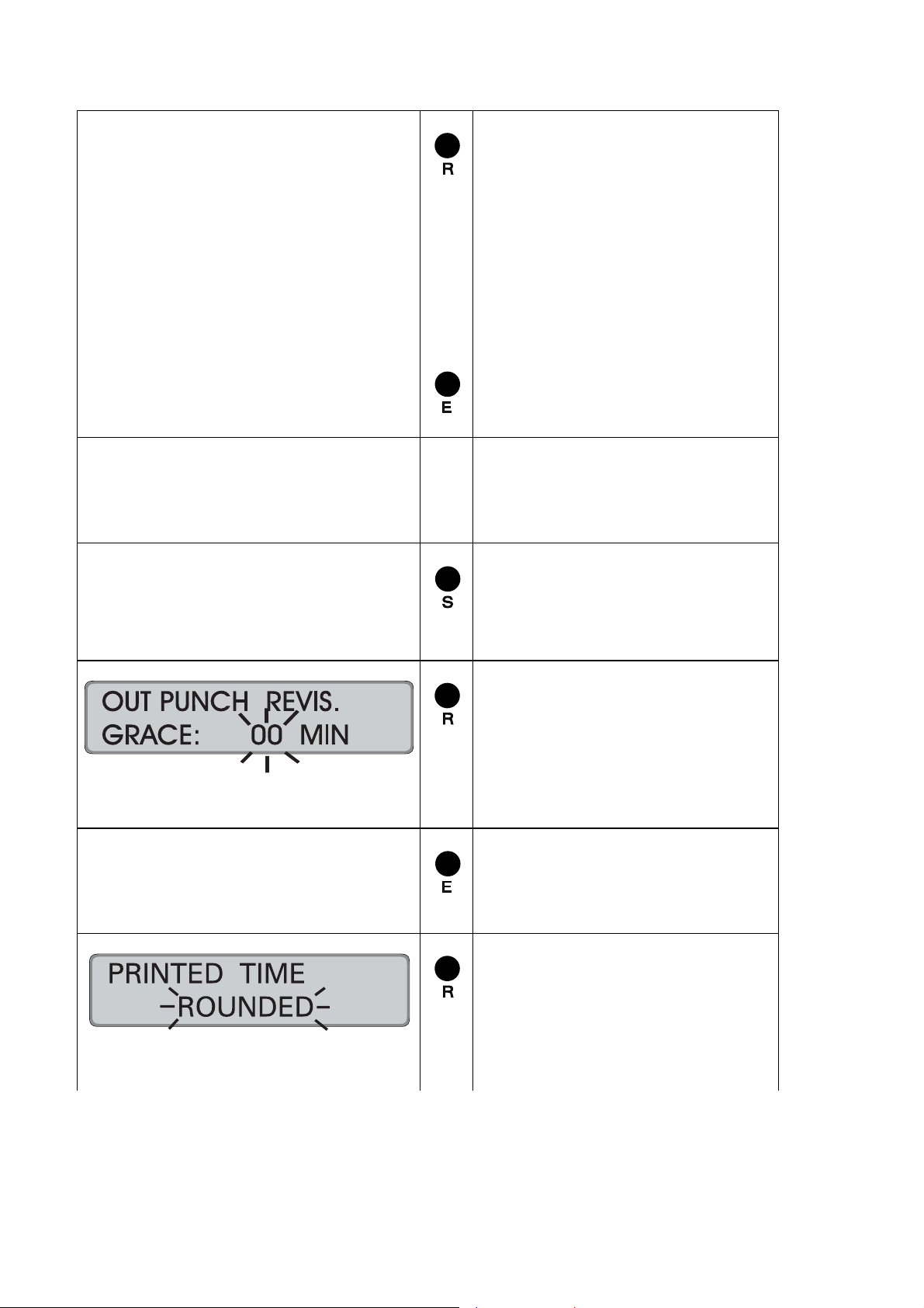
= Select the "copy to" day (or
days)
Hint: With this f unction you
can copy the defined values
directly to consecutive
weekdays. All you do is select
the last consecutive weekday
instead of just the next
weekday, e.g. Friday instead of
Tuesday.
= Confirm 2nd input field.
Repeat the copying process if
further schedules with OUT
punch revision shall be copied to
other weekdays.
= Switch over to next input level,
when you have copied all
schedules with OUT punch
revision.
= Set rounding qualification for
OUT punching.
Range of values: 0 - 59 min.
Note: By keeping this key
pressed the value is scrolled.
= Confirm selection.
Recorder changes to next
input level.
= Select time to be printed on
the card:
Range of values:
rounded,
unrounded.
4-36 Getting Started Chapter 4

Hint
If, in addition, the PUNCH ROUNDING function is activated, the
recorder ignores the settings of the PUNCH ROUNDING function
during an OUT punch revision time range.
= Confirm selection and return to
menu level.
= Continue with next parameter.
Hint: Use "E" to return to the
input level.
Chapter 4 Getting Started 4-37

Change or Delete Values for schedules with OUT Punch Revisions
The OUT Punch Revision schedules can be modified at any time. Use the copy
function in order to change or delete several days at a time.
Procedure:
1. Call-up the programming routine. ("R" key)
2. Select the "OUT Punch Revision" menu ("S" key)
3. Select the weekday on which changes
are to be made. ("R" key)
4. Call up the time value to be changed. (Click through with "E" key)
5. Change the beginning or end of the schedule ("R" and "E" keys)
with OUT Punch Revision / or change the time value
If you want to delete the displayed time value,
set the 1st input field "Beginning /end of the schedule with
OUT punch revision " to "− −"
and confirm with "E".
The 2nd input field "Time value" is then deleted
and the next value is displayed.
→ To make further changes for this weekday,
repeat steps 4 and 5.
6. Complete settings for this weekday: ("S" key)
→ In order to make changes for other weekdays,
repeat steps 3 to 6 or:
7. Skip to "Copy function" to
copy the changed weekday to further weekdays. ("S" key)
8. Select the "day range“ which the
changed day schedule will be copied to. ("R" and "E" key)
9. Quit copying function and skip to. ("S" key)
next input level "enter grace"
10. Change qualification value ("R" and "E" key)
11. Switch over to next input level ("S" key)
"printed time"
12. Select form of printed time ("R" and "E" key)
13. Quit the "OUT Punch Revision" menu ("S" key)
14. Quit the programming routine (continue with "S" key)
→ Date and time are displayed.
4-38 Getting Started Chapter 4
Automatic Break
By enabling this function it is possible to control the calculation of the total of daily
paid and unpaid breaks. Up to 4 break rules can be defined in the unit. The rules are
not linked together. With each punching pair the fulfilling of the rule conditions is
checked. Each rule depends on 4 parameters:
Elapsed Time If this qualification value is reached or exceeded, the
checking, which rule condition shall apply, is started.
Elapsed Time = Difference from last OUT punch minus
first IN-punch.
Min. Deduct The break value entered here is always deducted from
Elapsed Time if
- no breaks are punched
- breaks are punched too short.
Hint
If the total of punched breaks is smaller than
the value of Min. Deduct, the difference
between Min. Deduct and the total of the
punched breaks is additionally deducted
from the Elapsed Time.
If the total of punched breaks is equal or
greater than the Min. Deduct value, no
additional deduction is effected.
Min. Worked If the qualification value of "Elapsed Time" and also the
qualification value entered here are reached by working
time, the value of parameter "Paid Break" is added to the
worked total.
Worked Total = Elapsed Time minus break times.
Hint
Always the greater of the following two
values is deducted as break time:
Punched breaks or Min. Deduct
Paid Break The value entered here is added to the worked time if the
value of Elapsed Time and Min. Worked of one rule are
reached or exceeded.
Chapter 4 Getting Started 4-39
Example 1:
Hint
For the determination, which break rule is to be calculated,
2 conditions must be fulfilled
- the Elapsed Time is reached or exceeded
- the Min. Worked is reached or exceeded
Rule 1 Rule 2
Elapsed Time
Min. Deduct
Min. Worked
Paid Break
IN
8:00 9:00
9:15 11:50
12:15 14:00
14.10 17:00
OUT Conditions for the determination
4.00 7.00
0.10 0.20
3.00 6.00
0.10 0.20
of the break rule
- Elapsed Time is reached
- Worked Total is equal or
greater than Min. Worked
Elapsed Time = 9 - 8 = 1.00
! no rule is fulfilled
Elapsed Time = 11.50 - 8 = 3.50
! no rule is fulfilled
Elapsed Time = 14 - 8 = 6.00
! 1. condition of rule 1
is fulfilled
Worked Total = 6 - 0.40 = 5.20
! 2. condition of rule 1
is fulfilled
Elapsed Time = 17 - 8 = 9.00
! 1. condition of rule 2
is fulfilled
Worked Total = 9 - 0.50 = 8.10
! 2. condition of rule 2
is fulfilled
Rule
-
-
1 6 - 0.40 - 0.00
2 9.00 - 0.50 - 0.00
Calculation
Elapsed Time
- Punched Breaks
- Difference to Min.
Deduct
+ Paid Break
+ 0.10 = 5.30
+ 0.20 = 8.30
Interval
Total
1.00 1.00
2.35 3.35
1.55 5.30
3.00 8.30
Card
Total
4-40 Getting Started Chapter 4

Example 2:
Rule 1 Rule 2 Rule 3
Elapsed Time
Min. Deduct
Min. Worked
Paid Break
IN
7:00 9:00
9:07 10:43
10:49 11:13
11:27 16:14
OUT Conditions for the determination
4.00 6.00 9.00
0.15 0.30 0.45
3.30 5.30 8.30
0.05 0.10 0.20
of the break rule
- Elapsed Time is reached
- Worked Time is equal or
greater than Min. Worked
Elapsed Time = 9 - 7 = 2.00
! no rule is fulfilled
Elapsed Time = 10.43 - 7 = 3.43
! no rule is fulfilled
Elapsed Time = 11.13 - 7 = 4.13
! 1. condition of rule 1
is fulfilled
Worked Total = 4.13 - 0.15 =
3.58
! 2. condition of
rule 1 is fulfilled
Elapsed Time = 16.14 -7 = 9.14
! 1. condition of rule 3
is fulfilled
Worked Total = 9.14 - 0.45 =
8.15
! 2. condition of rule 3
is not fulfilled
Worked Total = 9.14 - 0.30 =
8.44
! Rule 2 is fulfilled
Rule
-
-
1 4.13 - 0.13 - 0.02
2 9.14 - 0.27 - 0.03
Calculation
Elapsed Time
- Punched Breaks
- Difference to Min.
Deduct
+ Paid Break
+ 0.05 = 4.03
+ 0.10 = 8.54
Interval
Total
2.00 2.00
1.36 3.36
0.27 4.03
4.51 8.54
Card
Total
Hint
If the function "FIXED BREAK" is additionally enabled e.g. for a
fixed lunch break, the calculation of the Worked Total is changed
Chapter 4 Getting Started 4-41
as follows:
Worked Total = Elapsed Time minus Break Times (Punched
Breaks or Min. Deduct) minus Fixed Breaks (Non Accumulation
Times), see also examples 3 + 4.

Example 3:
Rule 1 Rule 2
Elapsed Time
Min. Deduct
Min. Worked
Paid Break
Fixed Break (Non accumulation) schedule = from PM 12:00 to PM 12:30
IN
8:00 9:00
9:15 11:50
12:15 14:00
14.10 17:00
OUT Conditions for the determination
Elapsed Time = 9 - 8 = 1.00
! no rule is fulfilled
Elapsed Time = 11.50 - 8 = 3.50
! no rule is fulfilled
Elapsed Time = 14 - 8 = 6.00
! 1. condition of rule 1
Worked Total = 6 - 0.25 - 0.30
= 5.05
! 2. condition of rule 1
Elapsed Time = 17 - 8 = 9.00
! 1. condition of rule 2
Worked Total = 9 - 0.35 - 0.30 =
7.55
! 2. condition of rule 2
4.00 7.00
0.10 0.20
3.00 6.00
0.10 0.20
of the break rule
- Elapsed Time is reached
- Worked Total is equal or
greater than Min. Worked
is fulfilled
is fulfilled
is fulfilled
is fulfilled
Rule
-
-
1 6 - 0.25 - 0.00
2 9.00 - 0.35 - 0.00
Calculation
Elapsed Time
- Punched Breaks
- Difference to Min.
Deduct
- Fixed Break (Non
accumulation times)
+ Paid Break
- 0.30 + 0.10 = 5.15
- 0.30 + 0.20 = 8.15
Interval
Total
1.00 1.00
2.35 3.35
1.40 5.15
3.00 8.15
Card
Total
4-42 Getting Started Chapter 4

Example 4:
Rule 1 Rule 2 Rule 3
Elapsed Time
Min. Deduct
Min. Worked
Paid Break
Fixed Break (Non accumulation) schedule = from PM 12:00 to PM 12:30
IN
7:00 9:00
9:07 10:43
10:49 11:13
11:27 16:14
OUT Conditions for the determination
Elapsed Time = 9 - 7 = 2.00
! no rule is fulfilled
Elapsed Time = 10.43 - 7 = 3.43
! no rule is fulfilled
Elapsed Time = 11.13 - 7 = 4.13
! 1. condition of rule 1
Worked Total = 4.13 - 0.15 -
0.00
= 3.58
! 2. condition of rule 1
Elapsed Time = 16.14 -7 = 9.14
! 1. condition of rule 3
Worked Total = 9.14 - 0.45 -
0.30
= 7.59
! 2. condition of rule 3
Worked Total = 9.14 - 0.30 -
0.30
= 8.14
! Rule 2 is fulfilled
4.00 6.00 9.00
0.15 0.30 0.45
3.30 5.30 8.30
0.05 0.10 0.20
of the break rule
- Elapsed Time is reached
- Worked Total is equal or
greater than Min. Worked
is fulfilled
is fulfilled
is fulfilled
is not fulfilled
Rule
-
-
1 4.13 - 0.13 - 0.02
2 9.14 - 0.27 - 0.03
Calculation
Elapsed Time
- Punched Breaks
- Difference to Min.
Deduct
- Fixed Break (Non
accumulation times)
+ Paid Break
- 0.00 + 0.05 = 4.03
- 0.30 + 0.10 = 8.24
Interval
Total
2.00 2.00
1.36 3.36
0.27 4.03
4.21 8.24
Card
Total
Chapter 4 Getting Started 4-43

Proceeding
= Activate the function.
Or:
Switch to the next parameter
with "S".
= Confirm setting.
Recorder changes to input
level with the qualification
values of the first break rule.
1. setting = Elapsed Time
2. setting = Min. Deduct
3. setting = Min. Worked
4. setting = Paid Break
= Set Elapsed Time of first break
rule.
Format: HH.MM
1st input field = hours
2nd input field = minutes
= Set desired hour
Range of values: 00 - 18
= Confirm setting
= Enter the desired minutes
Range of values: 00 - 59
= Confirm setting
Recorder changes to next
menu level
Hint: By keeping this key
pressed the value is scrolled.
4-44 Getting Started Chapter 4

= Set Min. Deduct of first break
rule.
Format: HH.MM
1st input field = hours
2nd input field = minutes
= Set desired hour
Range of values: 00 - 18
= Confirm setting
= Enter the desired minutes
Range of values: 00 - 59
= Confirm setting
Recorder changes to next
menu level
Hint: By keeping this key
pressed the value is scrolled.
= Set Min. Worked of first break
rule.
Format: HH.MM
1st input field = hours
2nd input field = minutes
= Set desired hour
Range of values: 00 - 18
= Confirm setting
= Enter the desired minutes
Range of values: 00 - 59
= Confirm setting
Recorder changes to next
menu level
Hint: By keeping this key
pressed the value is scrolled.
Chapter 4 Getting Started 4-45

= Set Paid Break of first break
rule.
Format: HH.MM
1st input field = hours
2nd input field = minutes
= Set desired hour
Range of values: 00 - 18
= Confirm setting
= Enter the desired minutes
Range of values: 00 - 59
= Confirm setting
Recorder changes to next
menu level
Hint: By keeping this key
pressed the value is scrolled.
Hint
The values for "Elapsed Time" and "Min. Worked" of the 4 rules
must be entered in ascending sequence, i.e. the values of rule 2
have to be greater than the values of rule 1.
Repeat the procedure for the
input of the qualification values
for the second, the third and
the fourth break rule.
= Continue with next parameter.
Hint: Use "E" to return to the
input level.
4-46 Getting Started Chapter 4

Fixed Break (Non Accumulation Times
It is possible to set 4 time ranges per weekday within which no time accumulation is
made.
The definition of such time ranges makes it possible to:
- program fixed breaks which are not added to the presence time and must not
be punched by the employees
- limit the working time to be calculated
Example A: Fixed break
Fixed break / non accumulation schedule on Monday
Schedule: from = AM 09:00 to = AM 09:15
IN OUT
AM 07:00 AM 09:00 AM 09:15 PM 12:15
= fixed break / no time accumulation
= presence time to be calculated
Example B: Limited working time
Fixed break / non accumulation schedule on Monday
1. Schedule from = AM 07:00 to = AM 07:29
2. Schedule from = PM 06:01 to = PM 08:00
IN OUT
AM 07:00 AM 07:15 AM 07:29 PM 06:01 PM 06:30 PM 08:00
= fixed break / no time accumulation
= presence time to be calculated
Chapter 4 Getting Started 4-47

Hint
In order to use this function also for punch pairs, where the OUT
punch is made after the date change, the fixed break (non
accumulation) schedule must also be defined beyond date
change.
In the input routine possible time settings for the following day
are automatically marked with "+" in the 12 hours mode as well
as in the 24 hours mode (see the following example)
Example C: Limited working time beyond date change
Fixed break / non accumulation schedule
from Monday PM 11:00 to Tuesday AM 01:00.
Schedule from = PM 11:00 to = AM +01:00
IN OUT
Mo PM 07:00 Mo PM 11:00 Tu AM 00:30 Tu AM +01:00
= fixed break / no time accumulation
= presence time to be calculated
Hint
If there should be no calculation of IN-punches on Tuesday from
AM 00:00 to AM 01:00, it is necessary to enter a corresponding
fixed break (non accumulation) schedule for Tuesday.
Factory setting: → function deactivated
Proceeding
= Activate the function
Or:
Switch to the next parameter
with "S".
= Confirm setting
Recorder changes to the next
input level.
4-48 Getting Started Chapter 4
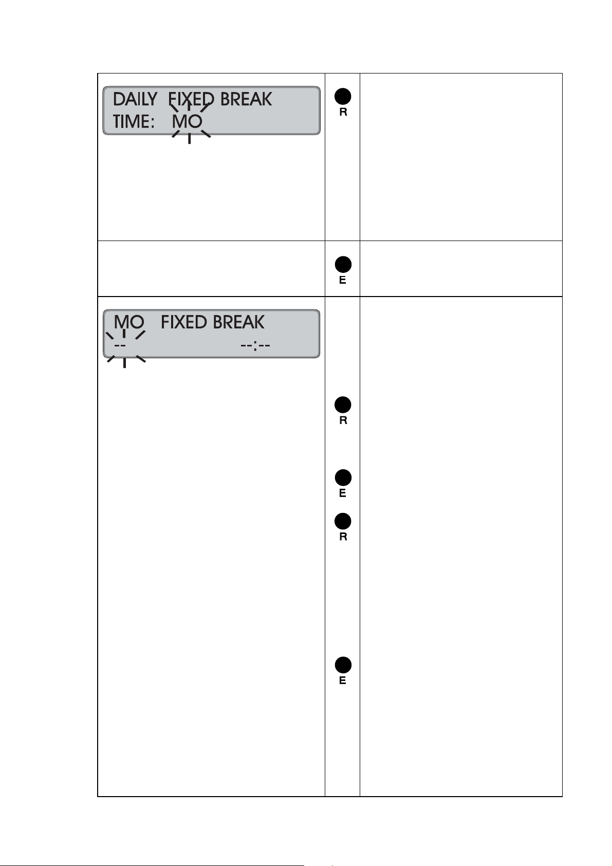
= Select the day of the week to
program the fixed break (no
accumulation) time range.
Range of values: MO to SU
Example: MO;
It is also possible to start on
any other weekday.
Note: By keeping this key
pressed the value is scrolled.
= Confirm selection.
1st input field = Start or
end of the
fixed break (no
accumulation)
time range
2nd input field = time value =
= Select function of the first input
field.
Range of values: FROM, TO,
−−,
= Confirm 1st input field
= Set the related time value in
the second input field.
Format: : hours, minutes
Hint: If the 12 hour time mode
is selected, a change from AM
to PM is to be achieved by
scrolling the hour value.
Possible time settings for the
following day are automatically
marked with "+" in the 12
hours mode as well as in the
24 hours mode.
= Confirm 2nd input field.
The values are stored and the
display is emptied, the first
input field flashes again.
Chapter 4 Getting Started 4-49

Repeat this procedure for further
fixed break (no accumulation)
time ranges for this weekday.
= Return to the previous input
level when you have entered
all fixed break (no
accumulation) time ranges for
this weekday.
Select a new day if fixed break
(no accumulation) time ranges
differ from the already defined
weekday.
Proceed as described above.
Or:
= Switch over to the copying
function.
Copying function
1st input field = "copy from"
2nd input field = "copy to"
= Select the "copy from" day.
= Confirm 1st input field.
= Select the "copy to" day (or
days)
Hint: With this f unction you
can copy the defined values
directly to consecutive
weekdays. All you do is select
the last consecutive weekday
instead of just the next
weekday, e.g. Friday instead of
Tuesday.
= Confirm 2nd input field.
4-50 Getting Started Chapter 4
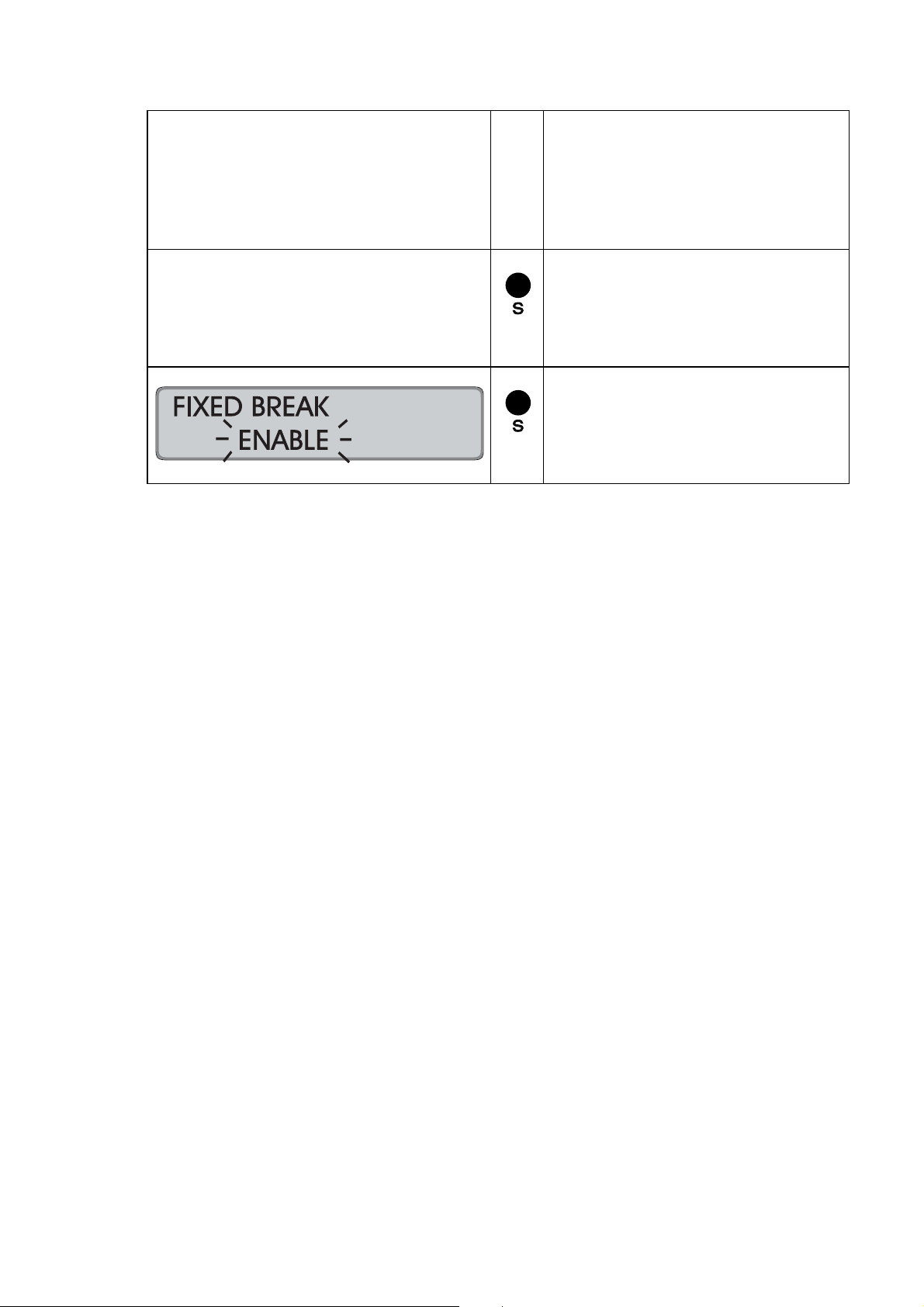
Repeat the copying process if
further fixed break (no
accumulation) time ranges shall
be copied to other weekdays.
= Return to the previous input
level, when you have copied all
fixed break (no accumulation)
time ranges.
= Continue with next parameter.
Hint: Use "E" to return to the
input level.
Chapter 4 Getting Started 4-51

Change or Delete Values for Fixed Break (no accumulation) Time Ranges
The fixed break (no accumulation) schedules can be modified at any time. Use the
copy function in order to change or delete several days at a time.
Procedure:
1. Call-up the programming routine. ("R" key)
2. Select the "Fixed Break" menu ("S" key)
3. Select the weekday on which changes
are to be made. ("R" key)
4. Call up the time value to be changed. (Click through with "E" key)
5. Change the beginning or end of the range without ("R" and "E" keys)
time calculation and / or change the time value
If you want to delete the displayed time value,
set the 1st input field "Beginning /end of the
fixed break (no accumulation) time range
" to "− −" and confirm with "E".
The 2nd input field "Time value" is then deleted
and the next value is displayed.
→ To make further changes for this weekday,
repeat steps 4 and 5.
6. Complete settings for this weekday: ("S" key)
→ In order to make changes for other weekdays,
repeat steps 3 to 6 or:
7. Skip to "Copy function" to
copy the changed weekday to further weekdays. ("S" key)
8. Select the "day range“ which the
changed day schedule will be copied to. ("R" and "E" key)
9. Quit copying function. ("S" key)
10. Quit the "Fixed Break" menu ("S" key)
11. Quit the programming routine (continue with "S" key)
→ Date and time are displayed.
4-52 Getting Started Chapter 4

Red Print (Ribbon Color Change)
To highlight exceptional punches on a time card, the time recorder has the capability
to print in two different colors (black and red). It can be programmed to change color
up to 8 times a day.
The menu item "Red Print" is used to program print color changes. The user must
program a separate schedule for each day of the week. To simplify programming,
there is a "copy“ utility that allows the user to copy one daily schedule to another day
of the week without having to re-enter all of the time values again.
The time recorder will automatically sort ribbon color program instructions into
chronological order. A defined print color remains active until a different program
instruction is entered.
Example:
Monday → time value AM 07:01 for red ribbon.
Same day → time value PM 05:01 for black ribbon.
As a result, all punches between AM 07:01 and PM 05:00 will be printed in red
and all punches after PM 05:00 will be printed in black, until a different
programmed time instruction is entered.
Hint
Two conflicting time values for one weekday (e.g. a PM 05:00
program instruction for red print and a duplicate program entry
In order to simplify time value programming for each weekday, the recorder has a
copy function which allows copying the daily settings to the fields of the next day. If,
for example, the color change values of Monday shall apply for all workdays it will be
enough to define the values for Monday and then copy the settings for the next days
with the help of this function.
If you do not program the ribbon color change feature, all punches are printed in
black, the factory set default.
The ribbon color change feature can be programmed or existing programs edited at
any time.
Factory default setting: → function deactivated
for a black print) will not be accept ed by the time recorder. It will
prevent you from quitting "Red Print" with the "E" or "S" key until
you have corrected the conflicting instructions.
Chapter 4 Getting Started 4-53
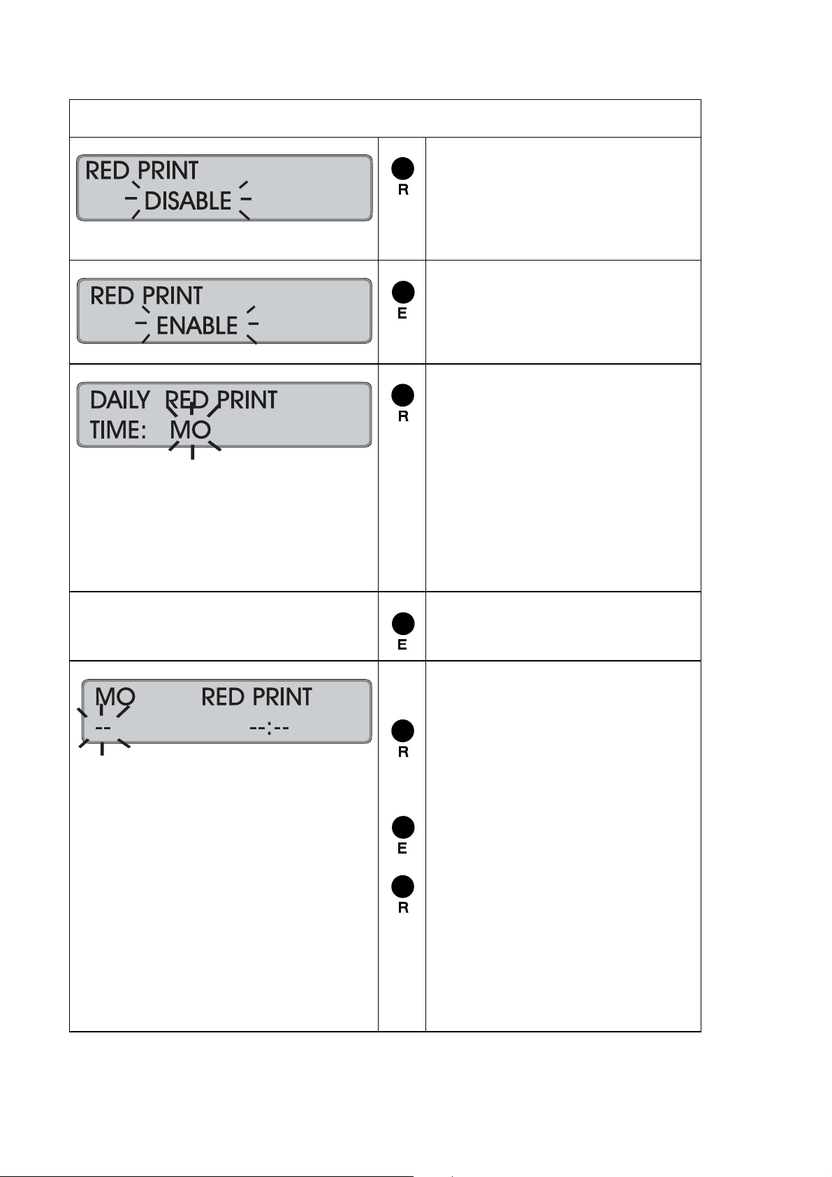
Proceeding
= Activate the function
Or:
Switch to the next parameter
with "S".
= Confirm setting.
Recorder changes to next input
level.
= Select the day of the week to
program the ribbon color
changes
Value range: MO to SU
Example: MO;
It is also possible to start on
any other weekday.
Hint: By keeping this key
pressed the value is scrolled.
= Confirm selection.
1. input field = print color
2. input field = time value
= Select the color in the first
input field.
Value range: −−, BLACK,
RED
= Confirm 1. input field.
= Set the related time value in
the second input field.
Format: AM/PM, hours,
minutes
4-54 Getting Started Chapter 4

Hint: If the 12 hour time mode
is selected, a change from AM
to PM is to be achieved by
scrolling the hour value.
= 2. Confirm input field.
The values are stored and the
display is emptied, the first
input field flashes again.
Repeat this procedure for further
ribbon color changes on this
weekday.
= Return to the previous input
level, when all ribbon color
changes for the weekday are
entered.
= Select a new day, where the
ribbon color schedule differs
from the already defined
weekday.
Proceed as described
previously.
Or:
= Switch over to the copy
function.
Copy function
1. input field = "copy from“
2. input field = "copy to“
= Select the "copy from“ day.
Chapter 4 Getting Started 4-55
= Confirm 1. input field.

= Select the "copy to“ day (or
days).
Hint: With this f unction you
can copy the defined values
directly to consecutive
weekdays. All you do is select
the last consecutive weekday
instead of just the next
weekday, e.g. Friday instead of
Tuesday.
= Confirm 2. input field.
Repeat the copy process if further
ribbon color change values shall
be copied to other weekdays.
= Return to the previous input
level, when all ribbon color
changes are copied.
= Continue with next value.
Hint: Use "E" to return to the
input level.
4-56 Getting Started Chapter 4

Change or Delete Values for Red Print / Ribbon Color Changes
The ribbon color change program can be modified or deleted at any time. Use the
copy function in order to modify or delete several days at a time.
Procedure:
1. Call-up the programming routine. ("R" key)
2. Select the menu "Red Print " ("S" key)
3. Select the weekday on which the changes shall
be carried out. ("R" key)
4. Call up the time value to be changed. (Click through with "E" key)
5. Change the affected program value. ("R" and "E" keys)
If you want to delete the displayed time value,
set the 1. input field "Print color" to "− −"
and confirm with "E". The 2. input field "Time value"
will be deleted and the subsequent pair of values
(print color and time value) will be displayed.
→ To make further changes to this weekday
repeat steps 4 and 5.
6. Exit programming for this weekday: ("S" key)
→ To make changes to other weekdays,
repeat steps 3 to 6 or:
7. Skip to "Copy function" to
copy the changed weekday to further weekdays. ("S" key)
8. Select the "day range“ which the
changed day schedule will be copied to. ("R" and "E" key)
9. Quit copy function. ("S" key)
10. Quit the menu "Red Print". ("S" key)
11. Quit the programming routine (continue with "S" key)
→ Date and time are displayed.
Hint
If you want to start the value input again and delete all color
change programming, just delete the values for one day and
copy that day to the rest of the week. If you just "disable" the
feature, the time re corder still remembers the existing
programming and restarts it the next time you "enable" the
feature.
Chapter 4 Getting Started 4-57

Overtime
By activating the function "Overtime" it is possible to calculate overtime.
If function "Overtime 2" is additionally activated it is possible to accumulate overtime
in 2 accounts.
Hint
If only overtime account 2 is enabled, it is not possible to
calculate overtime.
By selecting different qualification parameters it is possible to define the point of time
when overtime is to be calculated.
The following qualifications are available for both overtime functions:
Daily qualification Here the qualification value must be
reached within the day.
The daily qualification setting is valid
from Monday to Friday.
Saturday, Sunday and
public holiday qualification Special day qualification can be defined
for Saturdays, Sundays and public
holidays.
Weekly qualification The qualification value must be
reached within the week.
Reset weekly OT qualification Definition of the weekday on which the
calculation of a new weekly qualification
should begin.
Hint
After the reset of the weekly qualification, the normal working
hours and overtime are added in the total columns.
Definition of the weekly qualification
Normal working hours or
normal working hours + overtime In the definition of the weekly
qualification it is possible to select,
whether the qualification value is to be
reached by normal working time or by
normal working time plus overtime.
4-58 Getting Started Chapter 4
Definitions and qualification values for the following examples with only one
enabled overtime account:
Print format = 9 or 10
Daily qualification = 8 hours
Saturday qualification = 4 hours
Sunday qualification = 0 hours
Public holiday qualification = 0 hours
Weekly qualification = 40 hours
Reset weekly overtime = from Monday
Hint
When a qualification value is reached, working times over and
beyond that value are calculated as overtime, i.e., if 0 is set as
qualification, every minute worked is calculated as extra work.
If daily qualification is not required, "23.59" must be set as
qualification value.
If weekly qualification is not required, "99.59" must be set as
qualification value.
If function "Reset weekly overtime" should be disabled, "DS"
must be set.
Example 1 Weekly qualification with normal time
Employee works as
follows
Monday = 10 h 8 2 8 2
Tuesday = 9 h 8 1 16 3
Wednesday = 8 h 8 0 24 3
Thursday = 10 h 8 2 32 5
Friday = 9 h 8 1 40 6
Saturday = 6 h 0 6 40 12
Sunday = 4 h 0 4 40 16
Monday = 9 h 8 1 48 17
Tuesday = 6 h
(public holiday)
= weekly qualification
In Example 1, normal working time and overtime from Monday to Friday are
calculated according to the daily qualification the employee has reached.
On Friday the employee reaches the weekly qualification of 40 hours by his
normal working time, i.e. from that instant onwards all further working time is
calculated as overtime.
On Monday of the following week, the weekly accumulation of overtime begins
again. The totalization of normal working time and overtime is, however,
continued.
Diff.
normal time
0 6 48 23
Diff.
overtime
Total normal
time
Total
overtime
Chapter 4 Getting Started 4-59

Example 2 Weekly qualification with normal time + overtime
Employee works as
follows
Monday = 10 h 8 2 8 2
Tuesday = 9 h 8 1 16 3
Wednesday = 8 h 8 0 24 3
Thursday = 10 h 8 2 32 5
Friday = 9 h 3 6 35 11
Saturday = 6 h 0 6 35 17
Sunday = 4 h 0 4 35 21
Monday = 9 h 8 1 43 22
Tuesday = 6 h
(public holiday)
= weekly qualification
In Example 2, normal working time and overtime from Monday to Thursday are
calculated according to the daily qualification the employee has reached.
On Friday the employee reaches the weekly qualification of 40 hours after 3 hours
of normal working time, i.e. from that instant onwards all further working time is
calculated as overtime.
On Monday of the following week, the weekly accumulation of overtime begins
again. The totalization of normal working time and overtime is, however,
continued.
Diff.
normal time
0 6 43 28
Diff.
overtime
Total normal
time
Total
overtime
Hint
If, in addition, the DAY END function is activated, working hours
done after midnight can be used for calculating the overtime of
Factory setting: → function deactivated
Proceeding
4-60 Getting Started Chapter 4
the previous day. See also DAY END function.
= Activate the function
Or:
Switch to the next parameter
with "S".

= Confirm setting
Recorder changes to the input
level of the qualification
parameter.
1st setting = Daily
Qualification
2nd setting = Saturday
Qualification
3rd setting = Sunday
Qualification
4th setting = Public Holiday
Qualification
5th setting = Weekly
Qualification
6th setting = Reset Weekly
Overtime
qualification
7th setting = WK
Qualification
RT / RT + OT
Set daily qualification
Format: HH.MM
1st input field = hours
2nd input field = minutes
= Set desired hour
Range of values: 00 - 24
= Confirm setting
= Enter the desired minutes
Range of values: 00 - 59
= Confirm setting
Recorder changes to next
qualification parameter
Hint: By keeping this key
pressed the value is scrolled.
Chapter 4 Getting Started 4-61
Repeat the procedure for the
input of the qualification values
for Saturdays, Sundays and
Public Holidays.

Set weekly qualification
Format: HH.MM
1st input field = hours
2nd input field = minutes
= Set desired hour
Range of values: 00 - 99
= Confirm setting
= Enter the desired minutes
Range of values: 00 - 59
= Confirm setting
Recorder changes to next
input level.
Hint: By keeping this key
pressed the value is scrolled.
= Select weekday when the
weekly qualification is to begin
again.
Range of values: MO to SU,
DS (disable)
= Confirm setting.
Recorder changes to next
input level.
= Definition of the weekly
qualification
Range of values: RT / RT + OT
= Return to the previous input
level
= Continue with next value.
Hint: Use "E" to return to the
input level..
4-62 Getting Started Chapter 4

Option Menu
Key "E" = Entering of the Option Menu
Key "S" = End of Programming
When entering this menu further items are available
Calling up the Programming Routine for the Options Menu
To call up the programming routine for the option menu, the front cover of the
recorder must be removed. If the recorder is switched off, you must switch it on with
the mains switch. Refer to section "Switch on recorder".
Calling up the programming routine
→ Recorder is switched on.
Press "R" (at least 2 seconds) until display switches to
"ENT.EXISTING PIN".
If the program settings are kept:
Scroll through the existing
program settings with “S” until
recorder displays “OPTION
MENU”.
If existing program settings are to
be changed:
After having confirmed the last
menu item of the main
programming menu with key "E",
the recorder continues with
function "OPTION MENU".
= entering Option Menu
Recorder changes to next menu
item “CHANGE PINCODE”.
= End of Programming
Chapter 4 Getting Started 4-63
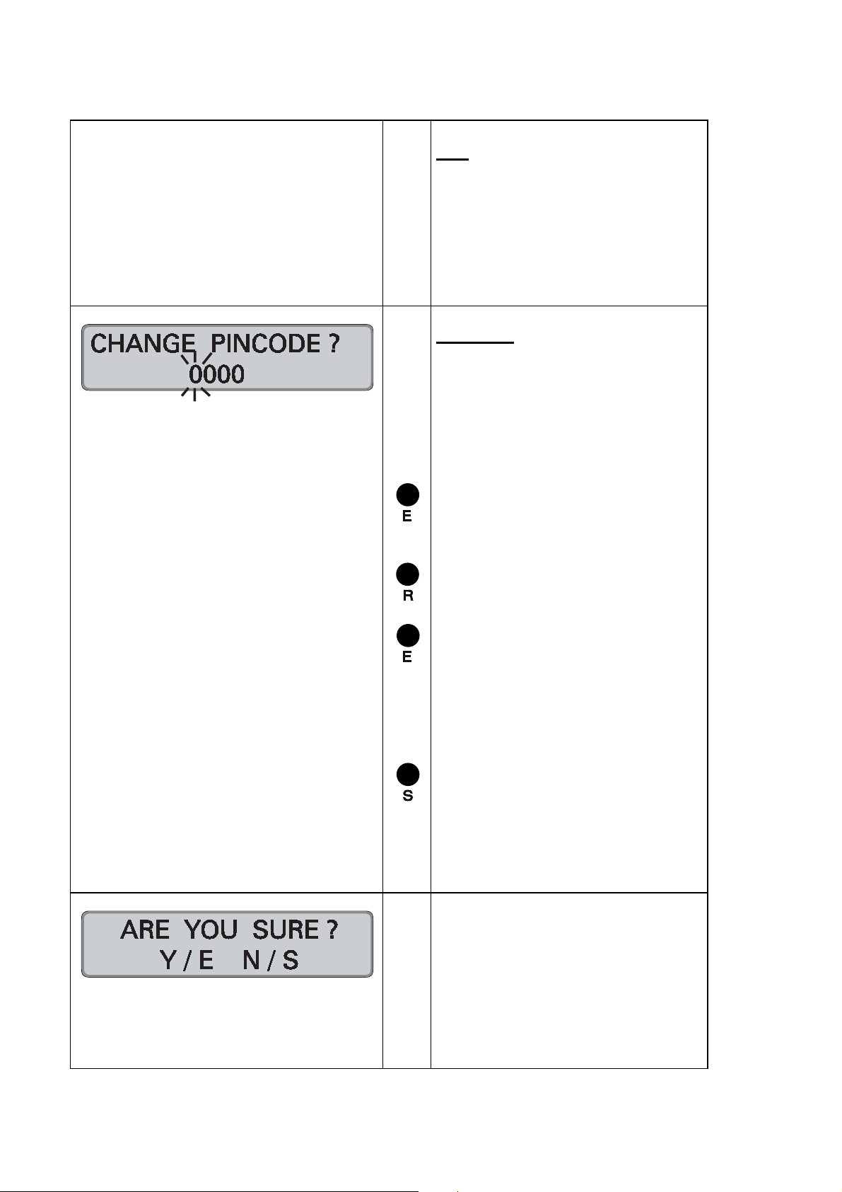
Hint
The "CHANGE PINCODE" field
appears every time you enter the
programming mode of the option
menu.
Enter the new PIN-code in the
same manner you enter the
existing PIN code.
Warning! Do not use the "E" key
when this prompt appears
otherwise you enter a PIN code
with the numbers 0000.
The entry of the code-number
begins with the left flashing digit.
If initial PIN is kept:
= confirm each digit
If individual PIN is entered
= enter each digit and
= confirm each digit
Recorder changes to next input
digit
= Complete the PIN-code input
and enable programming
routine of option menu. The
old PIN-code is preserved.
Recorder changes to next menu
item “DAYLIGHT SAVINGS”.
After having confirmed the last digit
with key "E" the recorder activates
the safety prompt.
Key "E" = Yes, accept new PIN
Key "S" = No, preserve old PIN
4-64 Getting Started Chapter 4

Daylight Savings Time
Daylight savings time changes can be programmed to occur automatically. You can
select either a perpetual automatic change over based on fixed rules of your
geographic area or you may select to program the time change every year based on
one time dates.
When selecting to use the one-time annual reprogram of daylight savings time
change, all time and date values must be re entered. These values will be valid for
one change-over only and will be automatically erased after the change-over has
occurred.
Hint
Please note that annual daylight savings time changes can only
be entered for future dates of the current calendar year. Program
instructions for the current year that refer to the past, are
automatically erased.
Factory default setting: → function deactivated
Proceeding
= Activate the function.
= Confirm setting.
Recorder changes to next
input level.
Chapter 4 Getting Started 4-65
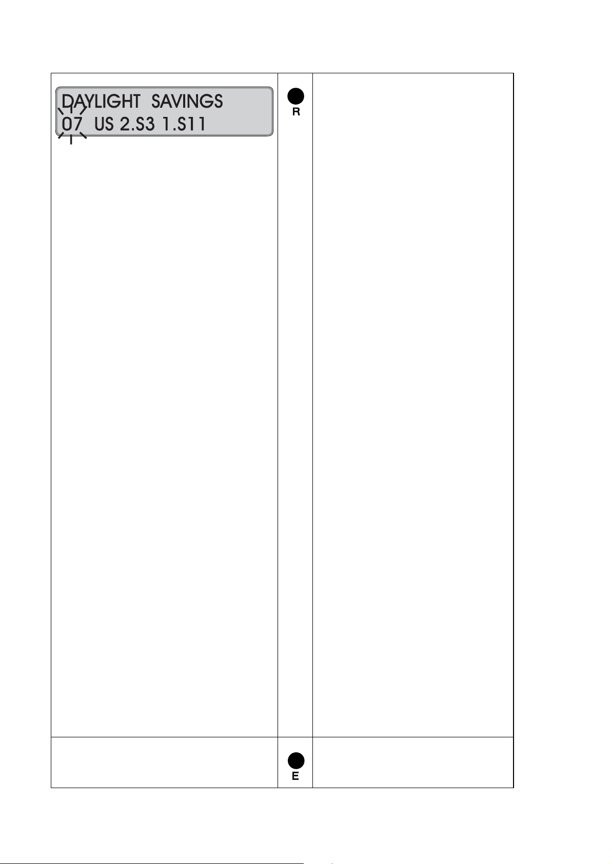
= Select switch-over mode.
01 = perpetual change
according to CET
last Sunday in March,
02:00 >> 03:00;
last Sunday in October,
03:00 >> 02:00;
02 = perpetual change
according to CET
last Sunday in March,
02:00 >> 03:00;
4. Sunday in October,
03:00 >> 02:00;
03 = perpetual change
according to GMT
last Sunday in March,
01:00 >> 02:00;
last Sunday in October,
02:00 >> 01:00;
04 = perpetual change
according to GMT
last Sunday in March,
01:00 >> 02:00;
4. Sunday in October,
02:00 >> 01:00;
05 = perpetual change
according to EEZ
last Sunday in March,
03:00 >> 04:00;
last Sunday in October,
04:00 >> 03:00;
06 = perpetual change
according to EEZ
last Sunday in March,
03:00 >> 04:00;
4. Sunday in October,
04:00 >> 03:00;
07 = perpetual change
according to USA
second Sunday in March ,
02:00 >> 03:00;
first Sunday in November,
03:00 >> 02:00;
99 = annual program change
= Confirm setting.
4-66 Getting Started Chapter 4

! If you have selected codes
"01" to "07", move to the next
field, "Deleting Cards“ by
pressing the "S“ key
! If you have selected code
"99", continue on with the
following sequence.
Recorder changes to next
input level.
First enter the spring change
over values.
Entry Order: Day, month, time
= Enter the desired day.
Hint: By keeping this key
pressed the value is scrolled.
= Confirm setting.
= Set desired month.
= Confirm setting.
= Select time of the switch-over.
First set the hour value.
Hint: If the 12 hour time mode
is selected, a change from AM
to PM is to be achieved by
scrolling the hour value.
= Confirm hour setting.
= Enter the minutes.
= Confirm setting.
Then the winter switch-over
values are entered.
Chapter 4 Getting Started 4-67
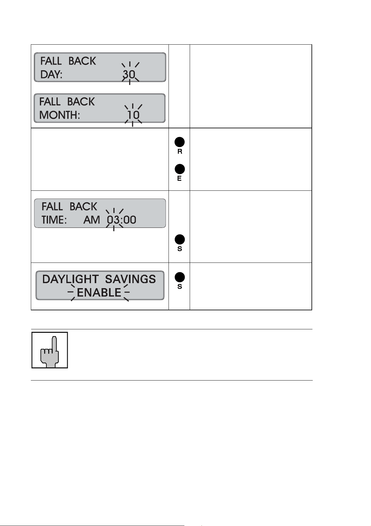
Proceed as described for
summer switch-over.
Order: Day, month, time
= Set the value.
= Confirm settings.
Hint: Do not use the "E" key for
confirmation after the minute
value input.
= Quit Daylight Savings Time
change-over and return to
menu level.
= Continue with next value.
Hint: Use "E" to return to the
input level.
Hint
In order to execute the daylight savings correctly, please do
not call up neither the programming routine nor the time/date
settings during the change over time, i.e., from 3 to 2 resp.
2 to 3 o'clock a.m.
4-68 Getting Started Chapter 4
 Loading...