

isel automation CPM 2018, CPM 4030, CPM 3020, GFV 44/33, GFV 44/73 Operating And Maintenance Instruction Manual
...Page 1
®
isel-CNC Compact Equipment
isel-CNC Machine
Operating and Maintenance Instruction
B.2801xx.06/2002.31/E
Order-number: _________________
Serial-number: _________________
Page 2
isel-CNC Compact Equipment CPM
On this Manual
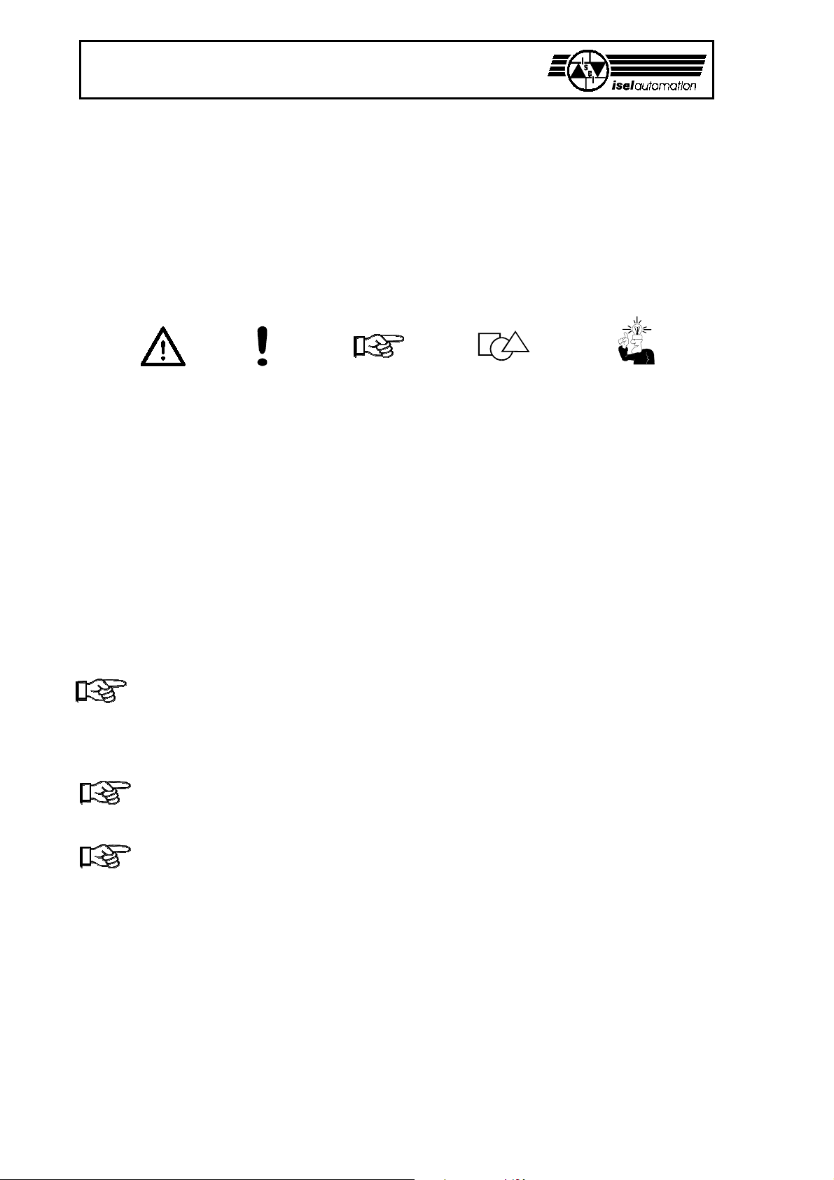
Various symbols are used in this Manual to quickly provide you with brief information.
Danger Caution Note Example Additional
Information
© iselautomation
All rights reserved.
Despite all care, printing errors and mistakes cannot be ruled out completely.
Suggestions for improvement and notes on errors are always welcomed.
isel machines and controllers are CE compliant and are marked accordingly.
Any other machine parts and components subject to the CE safety guidelines may not be
commissioned unless all relevent standards are fulfilled.
iselautomation shall not accept any liability for any modifications on the device by the
customer.
The limit values specified in the Certificate of Conformity only apply to the original
configuration from works.
Manufacturer:Co. iselautomation KG
E-Mail: system-sales@isel.com
http://www.isel.com
2
Page 3

isel-CNC Compact Equipment CPM
This manual includes the instructions for all machines of the CPM type.
The CPM is provided in three different system configurations.
The CPM as a compact equipment
The complete installation (mechanics, electronics, tooling machine and software
(ISY-CAM + REMOTE, I5DRV)) is immediately ready after commissioning.
At every expansion level, the CPM is a compact machine that offers an abundance of
possibilities for processing work pieces.
As a prerequisite for your work with the CPM and depending on the implementation, you
require basic knowledge in CNC engineering and PC application, a computer, a mains
socket, and some creativity.
Please, consider these short instructions to
• properly commission the equipment,
• fast, safely, and effectively work,
• keep away dangers of persons,
• and thus exploit the full potential.
We wish you a lot of success. Enjoy your future working with the CPM.
3
Page 4

isel-CNC Compact Equipment CPM
Contents
1 Intended use ..................................................................................................................... .5
2 Notes on safety ................................................................................................................. .6
3 Set up and connecting ..................................................................................................... .8
4 Cleaning / maintenance ....................................................................................................10
5 Commissioning ................................................................................................................12
5.1 Preparations .......................................................................................................................... .12
5.2 Adjustments .......................................................................................................................... .13
5.3 Important operating information ........................................................................................... .15
5.4 First commissioning .............................................................................................................. .17
6 Troubleshooting .............................................................................................................. .18
7 Technical data / accessory................................................................................................20
7.1 Accessory ............................................................................................................................. .20
7.2 Pin assignment ...................................................................................................................... .21
7.2.1 For the CPM with electronik ................................................................................................. .21
8 Appendix ...........................................................................................................................23
Certificate of conformity ........................................................................................................ .23
Service waybill ...................................................................................................................... .24
4
Page 5

1 Intended use
The CPM is a machine tool with three linear axes that can electronically be controlled.
A further (rotary) axis is available in addition.
- The machine is planned for training and the small assembly line production.
- It is designed for the application in dry rooms, business rooms, living and training areas and
in labs and small firms (min. 10°C / max. 40° C).
- The machine is suitable for milling, boring, cutting, engraving, proportioning, metering,
positioning, and many similar applications.
- You can install the most different suitable tooling tools or mount instruments, appropriate
for the above mentioned applications.
- Suitable tooling materials are aluminium, PVC, glass, printed circuit materials.(Please ask us
for further treatment materials)
For safety reasons, graphite is not permissible (danger of explosion) as material.
Also not admissible are materials that produce health-endangering gases during
processing.
isel-CNC Compact Equipment CPM
- The machine is prepared for a suction apparatus. With preference, this suctioning is
suitable for dry dust kinds.
With the ISY CAD/CAM software, you can directly pass on the previously generated
CNC data to the machine and initiate the processing of the work piece via a corresponding
controller program.
5
Page 6

isel-CNC Compact Equipment CPM
2 Notes on safety
- The machine must not be operated in a blast capable atmosphere.
- The machine is completely encapsulated. The casing protects you against moving tools,
decreases the operating noise level, and restrains the chips.
- While tooling, the hood is locked and can not be opened.
You may neither remove nor modify this protection measure (only type 2 and 3).
- Hardware and software are included in the safety circuit i.e. the machine functions only with
the appropriate and intact controller heart on the printed circuit board
(only type 2 and 3).
- For emergency situations, you find an Emergency-Off switch on the front-panel of the
machine.
It interrupts the power supply to the power module and tooling machine.
However, the software - machine communication remains possible for fault tracing
(only type 2 and 3).
- Only experts and trained persons may handle the keyswitch since a higher risk exists in test
mode (only type 2 and 3).
Please, keep the alternative key under lock and key.
- All 230 V loads are only single-pole switched. You must assume that an interrupted load is
not necessarily voltage-free (only type 2 and 3).
- Ensure sufficient ventilation at dust or gas development that is caused by processing the
materials.
- For cooling, no flowing water may be used but only a sprinkle/chilling appliance with which
a spray causes the cooling effect (see accessories).
No drops may form themselves and flow under the clamping plate.
- Do not use spirit as coolant (danger of explosion!).
- Clean the machine regularly and remove chips and dust deposits.
6
Page 7

isel-CNC Compact Equipment CPM
Aging of Safety Panes
Investigations, accomplished by the Association of German Machine Tool Factories (VDW) in
connection with the responsible employer's liability insurance association have pointed out
new aspects about the aging of polycarbonate as material for safety panes at machine tools.
Although polycarbonate worked very good for this purpose, these panes sometimes
substantially lose their ability to hold back flying around parts, especially under the influence
of cooling lubricants. At longer term, polycarbonate panes that are double-sided protected
against the effects of splinters, cooling lubricants, detergents, steams, etc. have hereby
shown the highest resistance.
In order to set you in the position to carry out your care business, we would like to point out
that safety panes made of polycarbonate are therefore to be examined regularly for their
retaining abilities and to be changed if necessary. Additionally, such safety panes are to be
classified as wearing parts in future. Beyond that, when you sale it, you are also obligated to
inform the possible buyer of such a machine accordingly about that.
Even with consideration of these new realizations polycarbonate will be further used as
material for safety panes in mechanical engineering due to its extremely high retaining ability.
Spare panes ready to be installed can therefore be ordered from us at any time. In order to
increase the necessary exchange intervals, we can also offer a retrofit kit for an additional
protection on the operator side if desired.
7
Page 8
isel-CNC Compact Equipment CPM
3 Set up and connecting
The machine is provided completely mounted on a palette.
Contained in scope of delivery of the CPM are:
• machine case with three linear axes included
- complete controller electronics
- drilling and milling machine with 3 mm split chuck - as a standard
• key for split chuck, spanner SW 17
• clamping set (hand lever, stop bars, 5 mm socket spanner)
• triangular wrench for unlocking the hood switch
• AC power cable, PC - machine data cable
• 4-fold socket outlet with illuminated mains switch
• software according equipment package
• and these service and maintenance instructions
• the parts of the scope of delivery can be variant by special systems
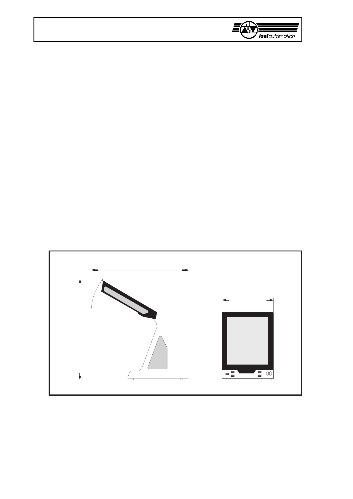
The space requirement of the machine is limited to the external measurements and to
sufficient room in front of the machine in order to operate and arrange the processing, plus
approx. 10 cm behind the machine to allow for connectors. The hood of the housing opens
upwards. Thus, the required total height is approx. 1,2 meters.
CPM 4030
CPM 3020*
CPM 2018**
710 mm
610 mm*
515 mm**
ca. 1270 mm
ca. 1200 mm*
ca. 1200 mm**
ca. 1200 mm
ca. 1200 mm*
ca. 1100 mm**
Dimensions and space requirement
Remove the sheet steels of the feet of the machine with which it is secured on the palette.
Then, set up the machine horizontally onto a flat, fixed face.
You can compensate for small unevenness of the base area at the feet.
During transportation, please pay attention to the supply and connection cables (remove if
needed) so that they are not damaged. Use only suitable lifting devices.
8
Page 9

isel-CNC Compact Equipment CPM
Above all, keep the triangular wrench always outside of the machine during
transportation.
The clamping set is made up by a hand lever clamping assembly and two stop bars with
mounting hardware for the T-slot plate.
Always ensure that the workpieces are
properly secured.
For the accessories, different parts are
already pre-installed or prepared for mounting.
For this purpose, also read the information in the appendix.
2 x
You can connect the cable of a tooling machine to the coupler
terminal block in the branch box at the side of the Z-axis.
9
Page 10

isel-CNC Compact Equipment CPM
4 Cleaning / maintenance
Open the hood before switching off the machine using the mains switch. After this, this is no
more possible.
Switch off the mains switch before any cleaning and any maintenance. Also, pull the
power plug in order to prevent an inadvertent starting.
Clean the machine regularly with a broom or vacuum cleaner of all chips (no compressed air).
That protects the mechanics against early wear.
- With frequent machining operations and very fine chips (dusts), you should regularly remove
the cover plate of the Y-axis below the T-slot plate and remove possibly penetrated chips
and/or dusts.
- The sealing lips include a Teflon component and require no special maintenance.
- Clean the perspex windows with a non-abrasive fluid cleaner.
- The shaft guides and drive shafts are provided with a long-term lubrication ex works.
Depending on the load, you should grease the shaft guides and drive shafts approx. all 500-
1000 operating hours. Use usual rolling bearing grease for that purpose.
Ex works, the shaft guides and shafts are lubricated using GP00/000F-20 sodium soap
grease according to DIN 51 502.
Please, you lubricate all 100-200 operating hours if you use oil.
At first, make a reference movement for lubricating the driving axis. Then, open the hood
and only now switch off the machine.
10
Page 11

In order to lubricate the Y-axis, you must
completely push* the T-slot plate to the
back. Next, unscrew (six screws) it from the
Y-axis.
Remove the plastic plug lying under it and
lubricate through the now visible lubricating
nipple.
You reach the shaft guides through the
sealing lips.
Loosen the all around holding-down screws
in order to remove the cover sheet of the Y-
axis.
S
in all drawings is the characterize accesses
to the greasing points.
isel-CNC Compact Equipment CPM
S
To lubricate the X-axis, move the
sledge to the left*. Remove the
plastic plug on the left side of the
machine and lubricate through the
now visible lubricating nipple.
You access the shaft guides again
through the sealing lips.
At the Z-axis, you must first take the tooling machine
from its support. Remove the three plugs and push the
sledge completely down*. You can apply some oil
onto the shaft guides through the two side holes.
The lubricating nipple for the drive is now behind the
front opening.
S
* You can displace the sledge using the hand if the
machine is off.
11
Page 12

isel-CNC Compact Equipment CPM
5 Commissioning
5.1 Preparations
For controlling the CNC machine and/or the FLASH EPROMs, you require one
IBM compatible computer with a free serial interface.
The system requirements of the control PC depends on the
respective operating system and the interpreter software (control software)
Connecting cables
The serial port is used as an interface of the machine to the computer using the enclosed
cable (max. three meters in length, you find the pin assignment of the 9-pin Sub D connector
in the Specification section).
Connect the red
connector of this cable to
the PC. This side of the
cable is again marked
with <<PC/AT<<.
Connect the gray coupler
on the reverse side of the
CPM.
Use the multiple socket
strip for connecting
power to the computer
and to the machine.
Connect the power cable
only if the machine is
ready for commissioning.
Mount the axis of rotation (optional) onto the T-slot plate in accordance with the assembly
and operating instructions of the axis of rotation in the appendix. Connect the cable to the
axis of rotation and the female Sub D-9 connector in the rear wall of the working space.
How to precisely set up the axis of rotation is also described in the assembly and operating
instructions in the appendix.
12
Page 13
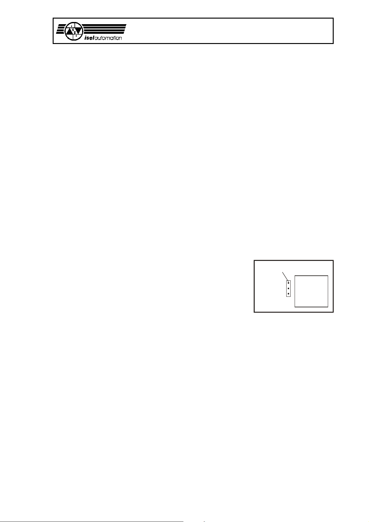
5.2 Adjustments
Setting of the transfer rate (baud rate) and/or of the delay period.
With the H1jumper field, you can set the transfer rate (9 600 or 19 200 bauds) and/or the
delay period of the hood switch (1 or 5 seconds).
- The baud rate is the transfer rate of the serial interface of the computer communicating with
the controller (see the manual for further information).
- Delay is the time passing by between the switching-off of the tooling machine (or the end of
tooling) and the releasing of the COVER button for opening the hood. Delay is used to wait
for the running out of the tooling machine to avoid dangers. Especially with educational and
training applications, 5 seconds of delay are reasonable and should also be set.
Pull the power plug before you place jumpers or remove them.
The jumper field is on the printed circuit board (in the figure on page 19, position 12).
isel-CNC Compact Equipment CPM
- Ex works, all jumpers are open, i.e. the baud rate is set to 19 200 bauds and the delay to
approx. 1 second.
- A jumper between pin 1 and pin 2 sets a baud rate of
9 600 bauds.
- A jumper pin 1 and 3 between extends the delay period to approx. 5 seconds.
jumper field H1
The new setting is taken over with the powering-up of the
machine.
All other jumpers on the printed circuit board must not be
1
2
3
processor
80C196K C
modified!
13
Page 14

isel-CNC Compact Equipment CPM
Tooling machine (only in the case of type 3)
In the collet , the standard tooling machine can take tools with a maximum shaft diameter
of 6.35 mm (standatd 3 mm, other diameters see Accessory). Use the sickle spanner and the
spanner SW 17 open end wrenches for changing the collet.
The current for the tooling machine is only enabled by
the software. You can manually adjust the rotation
speed of the machine using the wheel.
Switch off the main switch of the CPM for dismantling
the tooling machine. Remove the electricity cable from
the coupler terminal block, loosen the clamping screw
and take the tooling machine from the holder.
For dismantling the machine with the holder, remove
the electricity cable, the two outside screws
(loosen only, do not screw very out) and remove the
machine with holder and T-slot stones downwards.
Using corresponding holders, you can also attach many
other tools, measuring instruments (laser), or other
suitable equipment to the T-slot plate of the Z-axis.
Use the branch box at the Z-axis for the electrical connection.
If you want to mount the tooling machine or other tools again, you must realign the holder
parallel to the XY-plane.
14
Page 15

5.3 Important operating information
Push-buttons and switches
The black mains switch is located on the rear side of the machine directly beside the mains
connection.
Using the switches and/or push-buttons on the front side, you can switch the machine on and
off and start and stop the processing in a purposeful manner.
isel-CNC Compact Equipment CPM
Emergency-off
Abort of all functions; the error status remains
testable using the software; after a delay,
the hood can be opened using the push-button.
Releasing Emergency-Off by turning to the right.
POWER
You can only turn on the power stage if Emergency-Off is released.
Keyswitch
Using the key, you can switch between test and automatic operation.
AUTO = processing mode
In the automatic mode, the machine either works stand-alone based on the
program that is stored in the FLASH EPROM (CNC mode) or via the connected
supervisory computer (DNC mode). You can interrupt tooling using STOP and
continue to work using START.
TEST = test mode
In this operating mode, you can open the hood at any time if the tooling machine
is switched off. You can continue to process the programs. However, the tooling
machine is switched off if the hood is opened and can not be switched on again.
The sledge remains freely moveable also with manual traversing (teaching).
16 2345
Take care of the mobile sledge: Danger of bruising!
Pay attention to the moving-in depth: Collision danger with the work piece!
START
- If a program is stored on the FLASH EPROM then the program is started by pressing
this button independently of whether a computer is connected or not.
- After a hold using the button , the machine restarts the stopped movement
exactly at the location where it was interrupted provided that tooling has not being
terminated via the man-machine interface.
15
Page 16

isel-CNC Compact Equipment CPM
STOP
Execution of the current program is immediately stopped and remains at the (program)
location. The tooling machine is switched off. In the DNC mode, you can issue further
commands via software. This is not possible in the CNC mode.
After a time delay of 1 or 5 seconds, the COVER button lights up and you can open the
hood. With a closed hood, you can continue the program by pressing the START button.
COVER
Only if the button is lit, you can open the hood by pressing this button (first, press the
button, then pull simultaneously at the grip!). In the unfavorable case if you set only a
delay period of one second, the spindle can continue to rotate for a few seconds.
Do not reach into the still revolving tool.
16
Page 17

5.4 First commissioning
During the first commissioning, you should carry out the following steps:
- For the first opening of the hood, connect the power cable and turn on the mains switch.
The COVER button should light up now; you can open the hood if this button is lit.
- Emergency-Off must be released for all following functions.
- Close the hood and turn on the power stage using the POWER push-button ;
the push-button must light up.
- You can execute the software at any time. However, an error message is displayed if the
machine is not operational (power stage turned on).
- You can start a program stored on FLASH-EPROM by pressing the START button.
Of course, the machine must first be set up correspondingly.
- The hood is locked while tooling. You can only open the hood after the machine stands still,
the tooling machine is off, and the software enables the opening of the hood
(the COVER button lights up).
isel-CNC Compact Equipment CPM
- You must press the COVER button for opening the hood. The hood is automatically locked
after closing. To start the machine, you must press the START button again.
Please, refer to the corresponding software manual for all further information on working with
the software.
Keyswitch
For debugging the program, you can nevertheless open the hood during the operation if you
turn the keyswitch to TEST (test operation). In this case, the tooling machine must be
switched off but the work program is continued.
Take care to retract the tool from the work piece!
This key may only be used by expert and authorized personnel since no protection
against moving machine parts is available anymore after opening the hood.
Machining machine
The tooling machine is directly wired and switchable using the software.
The same applies to the three other switchable outputs (optional) that you can use to switch
optional devices (refer to the technical data).
The tooling machine can only be turned on if the POWER button is lit, the hood is locked
close, the rotary switch at the machine is set to ON, and the software controls the machine.
17
Page 18

isel-CNC Compact Equipment CPM
6 Troubleshooting
Fault Cause
Equipment can not be turned on No mains power is available check the mains circuit,
Mains switch is not turned on turn on the mains switch
Fuse is defective Pull the power plug
POWER button does not function Hood not closed close the hood
Emergency-Off not released release Emergency-Off
Fuse is defective Pull the power plug
Software does not work correctly Equipment not turned on turn on the equipment (mains switch)
Power stage not turned on activate power stage (POWER button)
Driver not loaded install the driver
Connection is not correct check the cable connectors
Tooling machine (spindle) Not released by the software reset the equipment and perform
does not function a reference movement
Rotary switch at the turn on the tooling machine
tooling machine is off
Remedy
power plug, multiple socket outlet
replace the fuse (see below)
replace the fuse (see below)
Fuse is defective Pull the power plug
Scaling of the axes Leadscrew pitch does not corres- Change the leadscrew pitch in the
is not correct pond to the setting in the software driver program to 4 or 10 mm
First movements do not correspond EPROM contents a program Delete the EPROM (s. page 16)
to the programm
replace the fuse (see below)
Fuse replacement
Pull the power plug before changing any fuse!
The main fuses of the machine are amenable from the outside. They are located directly
beside the power plug.
2
1
Remove the large rear-panel for
changing the other fuses. You find the
main fuse for the motor voltage in
front of the transformer in the black
plastic holder ( + : 6.3 A each ).
The remaining fuses are located on
the controller printed circuit board.
18
Page 19

isel-CNC Compact Equipment CPM
Please refer to the following drawing for the positions of fuses (, , , , ) and LED’s
(, , ).
Controller printed circuit board behind the rear-panel
Controller LED Processor supply voltage 10 V/5 V
Input fuse 1,25 Amp, slow ones
Controller LED 24 V I/O voltage
Input fuse 1,25 Amp, slow-blow
Controller LED 24 V safety circuit voltage
Input fuse 1,25 Amp, slow-blow
Supplementary output fuse 230 V, 1,25 Amp, slow-blow HBD
Supplementary output connector 230 V
Tooling machine fuse 230 V, 5 Amp, slow-blow HBD
suppl. outp. 9-pin Sub-D f. con. 15 mA max.
suppl. inp. 9-pin Sub-D fem. con.
H1 jumper field
For special cases (if a switch is defective or in case of power failure etc.), you can manually
open the hood interlock using the triangular wrench.
1. Switch off the machine and lift the machine.
2. Remove the four screws and the shield in the
bottom plate.
3. Insert the triangular wrench into the interlock
from below and turn it around half a turn to the
left without applying excessive force.
You may not operate the machine in this state.
The tooling machine remains de-energized.
Hole to the keyswitch (from below)
19
Page 20

isel-CNC Compact Equipment CPM
7 Technical data / accessory
CPM 2018 CPM 3020 CPM 4030
Measurements w x d x h [mm] 515 x 580 x 615 610 x 655 x 705 710 x 820 x 750
Movement areas X/Y/Z [mm] 200/175/90 295/200/130 395/300/140
maximum axis speeds [mm/s] 50 50 50
(without a load) all axes with 10 mm leadscrew pitch
Pass-through height [mm] 90 115 160
Clamping table [mm] 250 x 425 250 x 500 375 x 600
T-slot raster [mm] 25 25 25
Type 2 and 3
Approx. weight [kg] 71 76 89
Sound pressure level 78 decibel (A) 78 decibel (A) 78 decibel (A)
Mains rating 230 V, 50 Hz, 16 Amp
Max. power consumption 1150 W
Fusing power input 2 x 6.3 Amps, slow-blow HBD
Earthing corresponds to protection class I.
Electric connections 2 x 24 V, optional, switchable, 20 mA via optical isolator
1 x 230 V, optional, switchable, 100 W
1 x 230 V, switchable for the tooling machine
Tooling machine (model 3) 500 W, 11.000 - 25.000 r.p.m., firmly wired
EMC test according to EN 55011-B and EN 50082-1
Technical subject to change
7.1 Accessories
You can order the following accessories that matches the CPM: Order no.:
- additional collets for the spindle: e. g. 239 110 3000
1 to 5 mm in 0,5 mm steps, 6 mm and 1/8"
- additional mounting hardware for the T-slot plate e. g. 290 002
- working area light (not for type 1) 280 1XX 9004
- suction apparatus 280 1XX 9001
- vacuum cleaner 425 005
- engraving spindle (25 000 r.p.m.) with mech. hight offset 421520
- engraving pad 280 1XX 9003
- sprinkle/chilling appliance 280 1XX 9002
- axis of rotation on inquires
- grease gun 931 170
- length measurement unit 280 110 9010
With every accessory, pay attention to an expert assembly and consider the valid standards
and safety regulations.
In the appendix, you find the assembly and operating instructions for the accessories.
For further information and/or purchase orders, please turn to Technical consulting
CNC systems phone +49-6672-898-218, -489, -215
fax +49-6672-898-222
email system-sales@isel.com
20
Page 21

9
7.2 Pin assignment
7.2.1 For the CPM with electronik
The pin assignment of the connection cable for the serial interface:
isel-CNC Compact Equipment CPM
interface at
the machine
1
2
3
4
5
6
7
8
1
2
3
4
5
interface at
the computer
6
7
8
9
Please, consider the following notes if you want to custom-specifically setup the optional
supplementary inputs/outputs:
Let only specialists carrying out the work since otherwise danger exists for your life!
The numbers in the circles refer to the figure of the controller printed circuit board (page 19).
To the 24 V outputs:
You can tap the voltage at the 9-pin Sub D connector .
The switching outputs OPTO-5 and OPTO-6 are carried out with optical isolators with emitters
led outwards. They are available for signaling. These outputs are not disconnected in case of
Emergency-Off.
You must connect your loads against GND 24 V I/O (pins 6 to 9).
The maximum switching current should not exceed 15 mA!
The switching outputs are not short-circuit-protected.
Connection example:
Pin Description
1 + 24 V I/O voltage
2 out OPTO-5 (bit 5) open emitters
3 out OPTO-6 (bit 6) open emitters
4 free
5 + 24 V I/O voltage
6 GND 24 V
7 GND 24 V
8 GND 24 V
9 GND 24 V
extern intern
21
Page 22

isel-CNC Compact Equipment CPM
To the 24 V inputs:
Use the 9-pin Sub D connector (see image page 19). The input is carried out using an
optical isolator with the anode led outwards. The necessary series resistor is available on the
printed circuit board.
Pin Description
1 user input 2
2 user input 1
3 occupied
4 occupied
5 GND 24 V
6 + 24 V I/O voltage
7 occupied
8 occupied
9 GND 24 V
Connection example:
extern intern
Use pin 6 for the 24 V control voltage of both inputs.
Pins already used by iselautomation must not be modified. Otherwise, the machine can not
function properly.
230 V output:
Use the
You can replace the pre-installed tooling machine on terminals 2 and 4 by another machine
(max. power approx. 900 W).
Additional 230 V loads must be connected to terminals 3 and 5 and/or terminals 6 and 8.
A maximum of 1 Amp (200 W) can be drawn from output 3.
connector (see image page 19). The connector carries 230 V potential!
Terminal Description
1 230 V, live supply
2 switching output tooling machine
3 switching output 230 V OUT 3 (bit 3)
4 null tooling machine
5 null supply
6 null OUT 3
7 null OUT 4
8-
22
All 230 V loads are only single-pole switched. You must assume that an interrupted load
is not necessarily voltage-free.
In addition to the fusing and , all 230 V switching outputs (terminals 2, 3 and 8) are
protected by a common fuse at the power input.
Page 23

isel-CNC Compact Equipment CPM
280 100 2418 / 280 101 2418 280 110 2030 / 280 111 2030 280 120 2036 / 280 121 2036
280 100 3418 / 280 101 3418 280 110 3030 / 280 111 3030 280 120 3036 / 280 121 3036
Eiterfeld, den 11.07.02
23
Page 24

isel-CNC Compact Equipment CPM
8 Appendix
Service waybill (please, also consider the notes to the next page)
Sender
Company
Customer No.
Contact person/Dept.
Phone Fax
Postal address
Return to
Qty. Item number Designation Delivery Note No Serial number
Cause of the complaint
a) Financial complaint H wrong delivery H variance of quantity
H ________________________________________
b) Technical complaint
Error description
Invoice No./
(please add copy)
24
When does the fault occur?
H permanently H temperature dependent
H sporadic H after ___ minutes of operation
Was the item already in use?
H has not yet been used
H defectively by initiation
H ___months been in the use
date signature
Page 25

isel-CNC Compact Equipment CPM
Please, take note in case of returning the product!
1. Warrantee proof
For the examination of your warranty claim, a copy of the purchase bill or of the receipt is
required. We return the product unprocessed against a charge if this proof is missing.
2. Error description
In case of products arriving without precise error description at our facilities (“Defective” or
“For Repair” is not sufficient), we have the right to select between carrying out of a liable
to pay the costs fault diagnosis or the non-repaired returning against a service charge.
3. Inadmissible complaints
In case of inadmissible complaints (no fault is detectable, probable operator error), the
product is self-consciously returned against a service charge.
4. Wrapping
We can only accept returned products in original isel packing or equivalent wrapping.
The warranty claim is endangered by missing original or inappropriate wrapping.
Resulting transport damages cause the expiration of the warranty claim.
5. OEM products
Products which were not delivered by us are returned in a non-repaired manner against a
service charge.
6. Transport charges
iselautomation carries the transportation charge for returns from warranty claims. The
sender bears all other haulage. Product sent in without paid transportation charges can
not be accepted for organizational reasons.
7. Sales conditions, delivery conditions, and terms of payment
As for the rest, the sales conditions, delivery conditions, and terms of payment of
iselautomation are valid without change.
25
 Loading...