

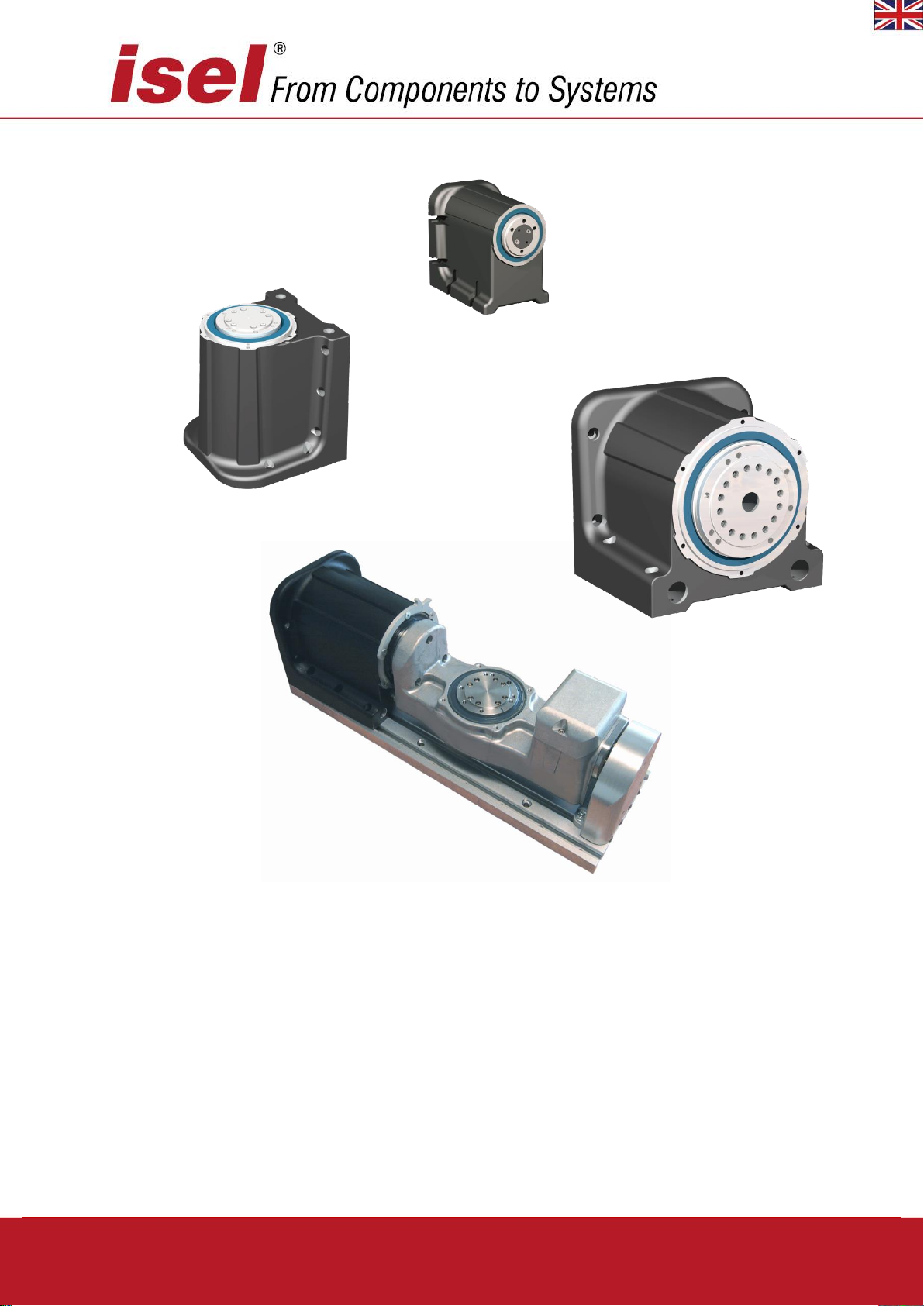
Rotary units with Harmonic Drive®
RDH-XS, RDH-S, RDH-M
RSH-S
Assembly instruction with:
- Installation instructions
- Maintenance instructions
- Declaration of incorporation
for a drive system
(A partly completed machine as defined in the Machine Directive 2006/42/EC)
© isel Germany AG, April 2019, english
RDH-XS, RDH-S, RDH-M, DSH-S
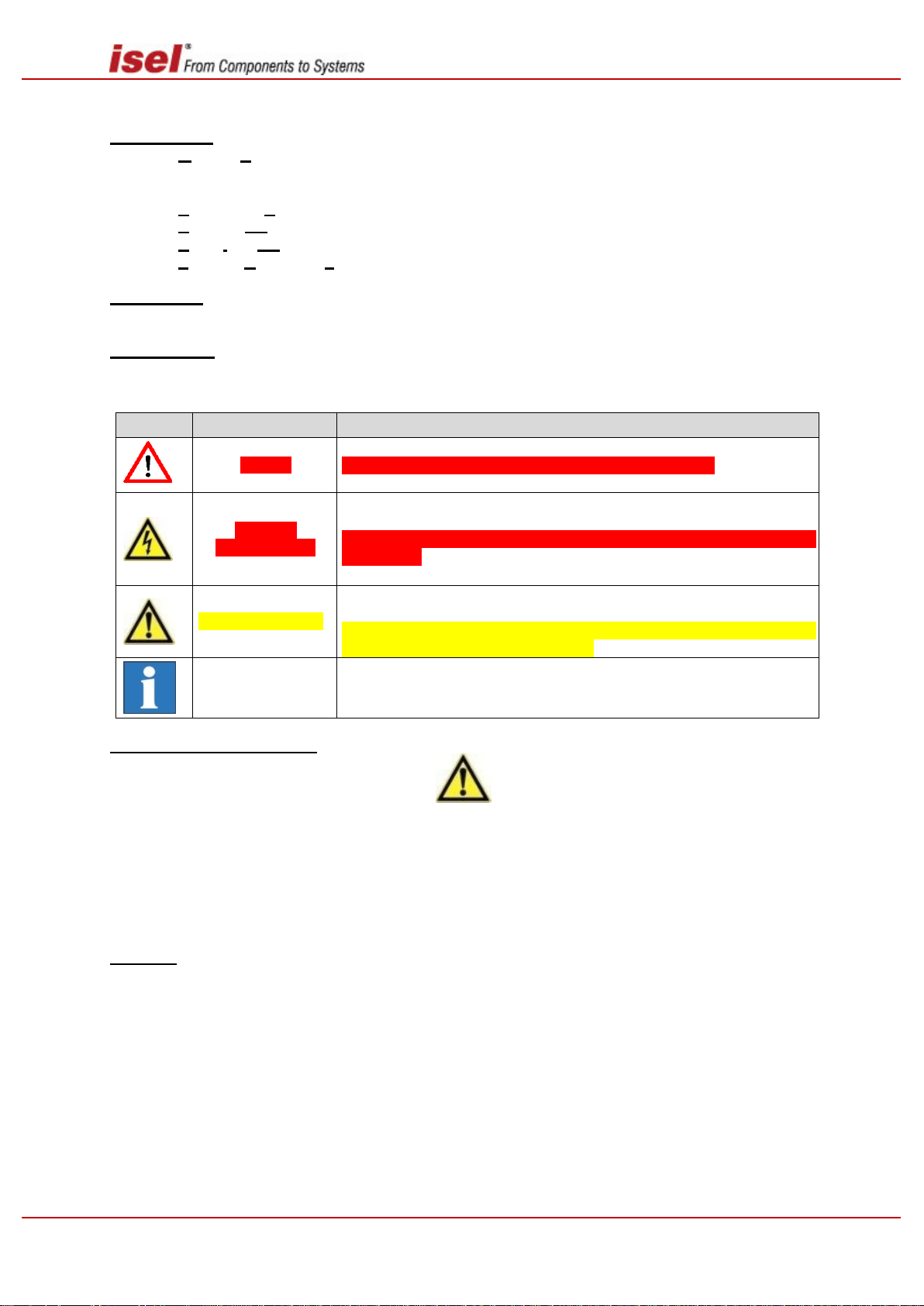
Symbol
Warning
Meaning
Danger
Warning of possible serious or fatal injuries to persons
Caution !
Fatal Voltage !
The flash symbol is a clear warning of danger from electric current!
Not heeding this warning can lead to personal injuries with fatal consequences.
Warning, caution !
Warning of possible minor injuries to persons, of possible faults or destruction of the product or possible damage to property.
Not heeding the facts following this symbol (text, picture or table) can
result in serious damage to property.
Important
information or
note
Important information or note on how the product works.
About these assembly instructions
Abbreviations
MD = MachineDirective 2006/42/EC
RDH = Rotary Index Table with Harmonic Drive® Motor
RSH = Rotary Swivel Unit with Harmonic Drive® Motor
AC = Alternating Current, AC servo motor (always synchronous motor)
BDC = Brushed DC, brush type Direct Current (DC) servo motor
BLDC = Brushless DC, brushless type direct current (DC) servo motor
PDF = Portable Document Format
Terminology
In these assembly instructions "product" always refers to a Rotary Unit with Harmonic Drive.
Symbols used
In these instructions you will find various symbols which are there to alert you to important information /
facts and hazards:
Readinig the safety guidelines
Before commissioning the Rotary Units (as partly completed machines), working with them, or making
any additions or modifications to the electrical installation, it is essential you read carefully:
the safety guidelines in these assembly instructions
the safety guidelines for electric drives and control systems in the instruction manual of the
positioning module, drive controller, drive module or drive controls used.
Copyright
© isel Germany AG, January 2013
All rights reserved
Although every care has been taken to avoid printing errors and mistakes, these cannot be ruled out.
We would be grateful for any suggestions for improvements or information on possible mistakes or unclear formulation of facts and illustrations.
2 / 44 April 2019

RDH-XS, RDH-S, RDH-M, DSH-S
Note on CE compliance for partly completed machines:
isel rotary units comply with CE guidelines. They are classed as partly completed machines as defined
in the Machinery Directive 2006/42/EC and therefore do not explicitly bear the CE mark.
Only after the compliance assessment procedures for the machine have been completed is the (complete) machine or system in which these linear units are installed awarded the CE mark by the manufacturer or distributor of the machine.
All other machine parts and/or machine components to which the CE safety guidelines apply must not
be commissioned until all the relevant requirements of Machinery Directive 2006/42/EC are met.
isel Germany AG does not accept any responsibility for any modifications you make to the rotary unit.
Manufacturer:
Processing date of this documentation: January 2013
More documents from isel Germany AG:
'Nothing is so good it can't be improved upon.' In accordance with this motto, as the manufacturer, we
are constantly improving all our manuals (including operating instructions and assembly instructions) at
considerable cost to ourselves.
We are committed to doing so since this is of benefit to both you as our customers and us:
We want you to be able to work efficiently with the relevant manuals and find the information you are
looking for quickly. Many details in the manuals are the result of information we have received from our
customers.
To support you, all the manuals are available to download in PDF format on our homepage:
https://www.isel.com/en/support-downloads/manuals.html
isel
Germany AG
Bürgermeister-Ebert-Straße 40
D-36124 Eichenzell
Tel.: (06659) 981-700
Fax: (06659) 981-776
E-Mail: automation@isel.com
http://www.isel.com
In your own interest:
Please read these assembly instructions carefully and keep them in a safe place. These instructions
form an integral part of the "Rotary Unit with Harmonic Drive" product, regardless of whether these instructions are supplied/available in the form of an electronic storage medium (as PDF file on a CD, DVD
or memory stick) or as a printed version.
Please read and follow the safety guidelines in these assembly instructions.
3 / 44 April 2019

RDH-XS, RDH-S, RDH-M, DSH-S
Contents
1 General information ....................................................................................................................... 5
1.1 Safety guidelines ....................................................................................................................... 6
1.2 Proper use ................................................................................................................................. 8
1.3 Deliverables .............................................................................................................................. 8
2 Installation instructions and overview of functions................................................................... 9
2.1 Functions ................................................................................................................................... 9
2.2 Assembly / of the rotary units /drive elements ........................................................................ 10
2.3 Connector pin assignment for rotary units .............................................................................. 27
3 Commissioning, general information ........................................................................................ 28
4 Assembly of the rotary unit ........................................................................................................ 29
4.1 Mounting and adjustment instructions .................................................................................... 29
4.2 Mounting the tailstock unit ...................................................................................................... 30
5 Fault list ........................................................................................................................................ 31
6 Technical specification ............................................................................................................... 32
6.1 Mechanical data ...................................................................................................................... 32
6.2 Electrical data .......................................................................................................................... 35
7 Maintenance and cleaning .......................................................................................................... 35
7.1 Maintenance instructions ........................................................................................................ 35
7.2 Cleaning .................................................................................................................................. 35
8 Decommissioning / disposal ...................................................................................................... 36
9 CE Conformity .............................................................................................................................. 36
10 Service .......................................................................................................................................... 37
11 Warranty ....................................................................................................................................... 37
12 Declaration of incorporation according to MD 2006/42/EC ..................................................... 38
13 Index .............................................................................................................................................. 39
14 Appendix ....................................................................................................................................... 40
14.1 A1: Accessories ................................................................................................................... 40
14.2 A2: Miscellaneous ............................................................................................................... 41
4 / 44 April 2019

RDH-XS, RDH-S, RDH-M, DSH-S
1 General information
This manual contains all important information about the assembly/installation, commissioning and
maintenance of your rotary units. In addition, it provides information and important notes for your safety.
The isel-rotary units RDH - RSH are rotary modules with Harmonic Drive® Motors, which are ready to
install. They are for use mainly in machining and positioning tasks in factory automation, handling technology and light machinery construction.
These rotary units are available in different standard sizes with various gear reductions.
The options for horizontal or vertical positioning of the rotary axis on the RDH series mean users can
build a wide variety of constructions to suit their requirements.
Please note:
The product is classed as 'partly completed machine' and not a (complete) machine according
to MD 2006/42/EC.
5 / 44 April 2019

RDH-XS, RDH-S, RDH-M, DSH-S
The following guidelines on safety and danger are intended to protect you, third parties
and the product. It is essential that you follow them.
1.1 Safety guidelines
Operating environment
The surrounding medium must not have a corrosive effect on aluminium alloys, stainless steels
(1.4305) or ABS plastics.
The product has achieved Protection Type IP65 if no corrosion has been caused on the surface
of the radial shaft seal by the operating environment.
When moving the product from cold to warm conditions, allow the product to adjust to the change
in temperature for a few hours, to avoid possible damage from condensation.
Do not install the product near devices which generate powerful magnetic fields. This could
disturb some products main functions.
Avoid environments exposed to direct solar radiation, considerable heat, cold, humidity or mois-
ture.
Power supply (only applies to products with multiphase motors, brushed DC/brushless DC or
AC servo motors and a suitable motor output stage/controller)
Only connect the power supply of the multiphase motor/servo motor output stage iMD10/iMD20,
the link to the servo motor output stage iMD40 (terminals L, N, PE) or the single-axis or multiaxis controller (e.g. iMC-P/iMC-S8, MC-1 series, iPU series…) to an earthed mains socket with
a mains voltage of 230 V AC/50…60 Hz (1-phase AC power supply).
It is preferable to use for the final stage of the mulitphase motor or the final stage of the
iMD10/iMD20 servomotor the original power supply recommended by isel Germany AG (primary
power supply: 230V AC, secondary: 48V DC). Using a different, inappropriate power supply
renders the warranty null and void. In addition, using an inappropriate power supply entails risks
caused by electric current, such as electric shock, fire or short circuits!
If you notice faults, activate the EMERGENCY STOP button on the (single axis) controller, the
CNC operating panel/CNC console, the control panel/control cabinet or a handheld device. Activating the EMERGENCY STOP button interrupts the power supply to the motor output stage.
If the power supply used is damaged you must not operate it. Have a qualified technician check
and if necessary repair the product.
The rotary unit
For safety reasons you must not convert and/or modify the rotary unit on your own.
In operation, the rotary unit must not be concealed by supplies (electricity or compressed air),
objects (e.g. tools) or tarpaulins, packaging or other materials etc. (e.g. clothing), because this
can lead to mechanical damage or heat obstruction and sometimes fire.
If using a single-axis/multi-axis controller to control a linear unit (equipped with an AC, brushed
DC (BDC) or a brushless DC (BLDC) servo motor), you need to ensure that the controller or
motor output stage used (in a control cabinet or on a mounting rack) is placed in a well-ventilated
environment.
6 / 44 April 2019

RDH-XS, RDH-S, RDH-M, DSH-S
Operation
(applies only to products supplied with a motor and a suitable motor output stage or a suitable
controller, e.g. a single-axis controller)
Only if the product is assembled correctly and the motor, the tactile or inductive limit switches, the brake
and the incremental measuring system (encoder) are correctly connected to the motor output stage/controller all further operations can be successful. Next operations are parameterization, commissioning
and operation/programming of the product as a fully-functioning drive system.
The technical details of special versions may differ from the following versions.
If the product malfunctions or you are unclear about its operational status, you should consult the relevant operating instructions/assembly instructions.
https://www.isel.com/en/support-downloads/manuals.html
Here you will find instructions and information on how to check the functions you require, remove the
causes of a possible malfunction or have these removed.
You must always carry out the instructions you find completely and correctly in order to ensure the
product functions correctly.
Never allow children or other persons who are vulnerable or at risk to operate the product unsupervised.
If you are still unclear about its operational status, it is highly recommended that you consult isel Germany, quoting the type and article number or serial number.
7 / 44 April 2019

RDH-XS, RDH-S, RDH-M, DSH-S
1.2 Proper use
The rotary units serve to rotate and position securely attached loads on the output flange in an environment where there is no danger of Exploded views and in accordance with the operational and environmental conditions specified for this product. The product can be installed as required (in a horizontal,
vertical or diagonal position).
The rotary units are a partly completed machine (compare Article 2g in the MD 2006/42/EC). Here a
partly completed machine is defined as follows (quote):
'A partly completed machine is a unit which almost forms a machine but which cannot fulfil any specific
function on its own.
A drive system is a partly completed machine.
A partly completed machine is only intended to be installed into other machines or other partly completed
machines or equipment or joined together with these to form a machine as defined in this directive.'
The rotary units RDH - RSH are intended for installation into a machine or into other partly completed
machines.
The product should not be used to transport people.
Any other use than those described above is not considered correct and can lead to personal injuries
and damage to property.
1.3 Deliverables
The deliverables include:
Assembly instructions and installation explanation according to MD 2006/42/EC
Mounting materials
Accessories if required
8 / 44 April 2019
RDH-XS, RDH-S, RDH-M, DSH-S
2 Installation instructions and overview of functions
Firstly, this section provides an overview of the mechanical structure, installation or assembly of the
rotary units and a description of their functions.
The instructions for commissioning/configuring the rotary unit and its programming by users depend on
the motors used and the relevant controllers with output stages; they can be found in their documentation.
2.1 Functions
The rotary units in the series RDH and RSH have a modular design.
These rotary units are based on extremely durable Harmonic Drive® motors with their well-known high
degree of precision.
These are housed in sealed aluminum molded shell and linked to a drive directly (solid shaft) or via a
drive belt (hollow shaft).
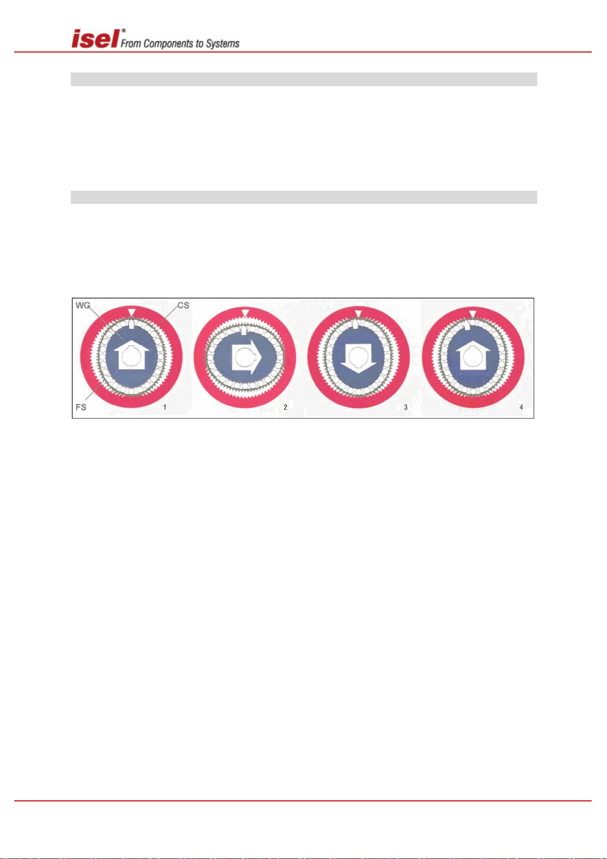
Operating principle of the Harmonic Drive-Transmission
Harmonic Drive motors are comprised of only three concentric components:
The Circular Spline (CS), a rigid cylindrical ring with internal gearing
The Flexspline (FS), a malleable cylindrical steel bushing with external gearing
The Wave Generator (WG), an elliptical steel disk with a centric hub and thin section ball bear-
ings
The powered elliptical Wave Generator (WG) deflects the Flexspline (FS), which is engaged with the
internal gearing of the fixed Circular Spline (CS) across the ball bearings.
In turning, the WG shifts the major axis of the ellipse axis and hence the position of tooth engagement.
The FS has two teeth less than the CS, so after half a WG rotary, a relative movement the size of one
tooth occurs between FS and CS (after a complete rotary this is equal to two teeth).
Where the CS is fixed, the FS is the output element and rotates in the opposite direction.
The following advantages result from this operating principle:
Reduction ratios of 30:1 to 320:1 with a minimal construction space
Peak torque values of 0.5 to 15000 Nm
Efficiencies of over 90% under rated operating conditions
Total positioning accuracy to less than one minute of an angle
Repeatability is only a few minutes of an angle
Freedom of movement in the tooth system
Very low tooth abrasion thanks to low sliding speed between the teeth
9 / 44 April 2019
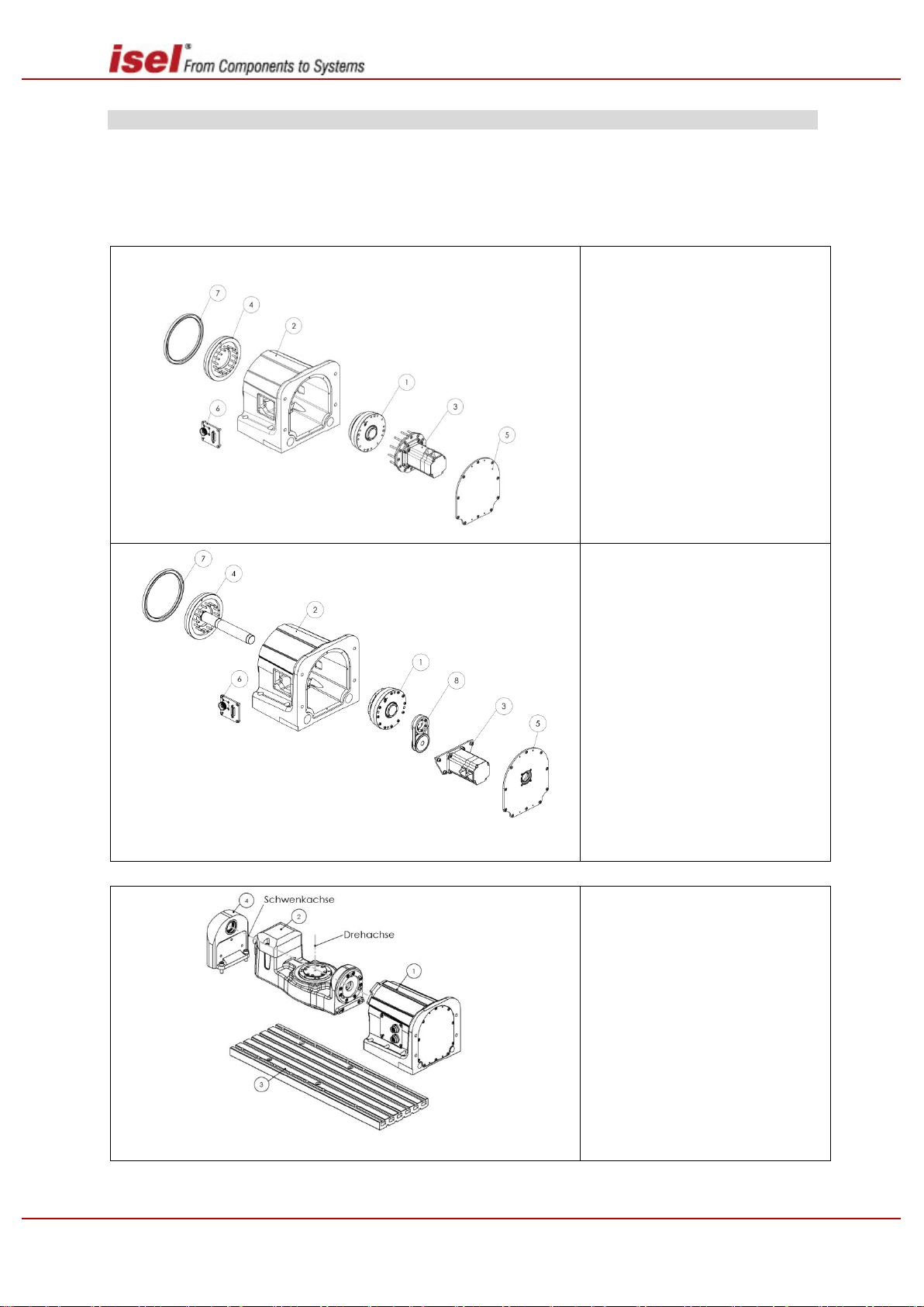
RDH-XS, RDH-S, RDH-M, DSH-S
Solid shaft
(1) Harmonic Drive Motor
(2) Aluminiummoulding shell
(3) Drive module
(4) Output flange solid shaft
(5) Cover
(6) Connection panel
(7) Rotary shaft seal
Hollow shaft
(1) Harmonic Drive Motor
(2) Aluminiummoulding shell
(3) Drive module
(4) Output flange hollow shaft
with pipe penetration
(5) Cover with penetration
and shaft seal
(6) Connection panel
(7) Rotary shaft seal
(8) Toothedbeltstage
Overview of the functions of DSH-S
* Schwenkachse = swivelaxis / Drehachse = rotationaxis
(1) Swivel module (RDH-S)
(2) Rotary axis
(3) Base plate
(4) Counterbearings
2.2 Assembly / of the rotary units /drive elements
The following illustrations, drawings and item lists illustrate the structure of the rotary units.
Options
Rotary units RDH – RSH are usually supplied ready for connection and with an integrated drive module.
The RDH-S and RDH-M units are also available as hollow shafts.
Overview of the functions using RDH-M as an example
10 / 44 April 2019
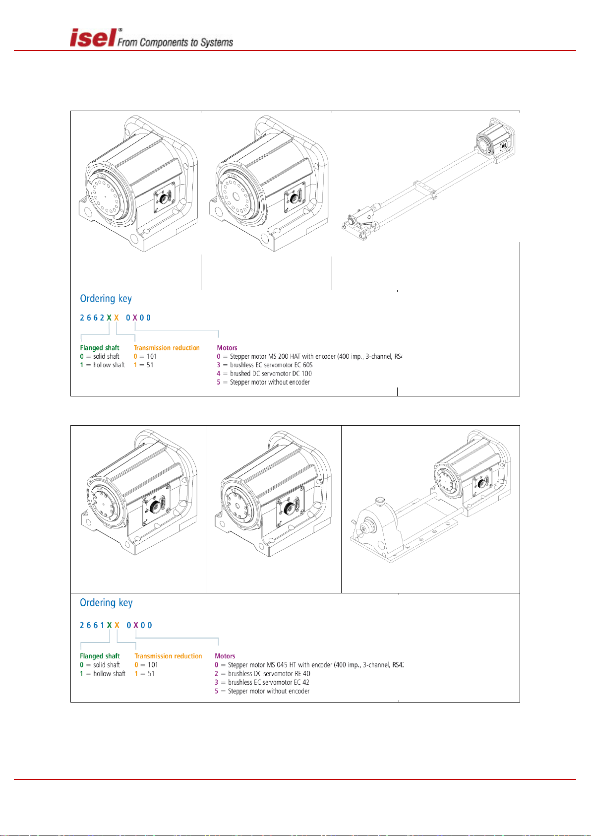
Options
RDH-M (Solid shaftoption)
RDH-M (Hollow shaft option)
RDH-M with tailstock unit RE M
Tailstock unit RE M
Art. No.: 269100 2100
(1000 mm)
Art. No.: 269100 2150
(1500 mm)
Art. No.: 269100 2200
(2000 mm)
RDH-S (Solid shaft option)
RDH-S (Hollow shaft option)
RDH-S with tailstock unit RE S
Tailstock unit RE S
Art. No.: 269100 1020
(200 mm)
Art. No.: 269100 1030
(300 mm)
Art. No.: 269100 1040
(400 mm)
Art. No.: 269100 1050
(500 mm)
RDH-M
RDH-XS, RDH-S, RDH-M, DSH-S
RDH-S
11 / 44 April 2019
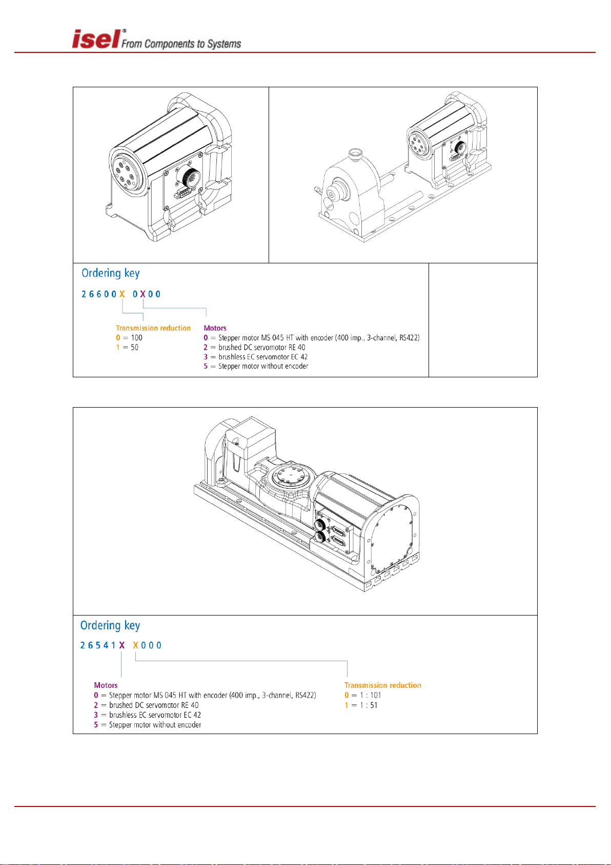
RDH-XS
RDH-XS (Solid shaftoption)
RDH-XS with tailstock unit RE XS
Tailstock unit RE S
Art. No.: 269100 0020
(200 mm)
Art. No.: 269100 0030
(300 mm)
Art. No.: 269100 0040
(400 mm)
Art. No.: 269100 0050
(500 mm)
RDH-XS with tailstock unit RE XS
RDH-XS, RDH-S, RDH-M, DSH-S
RSH-S
12 / 44 April 2019
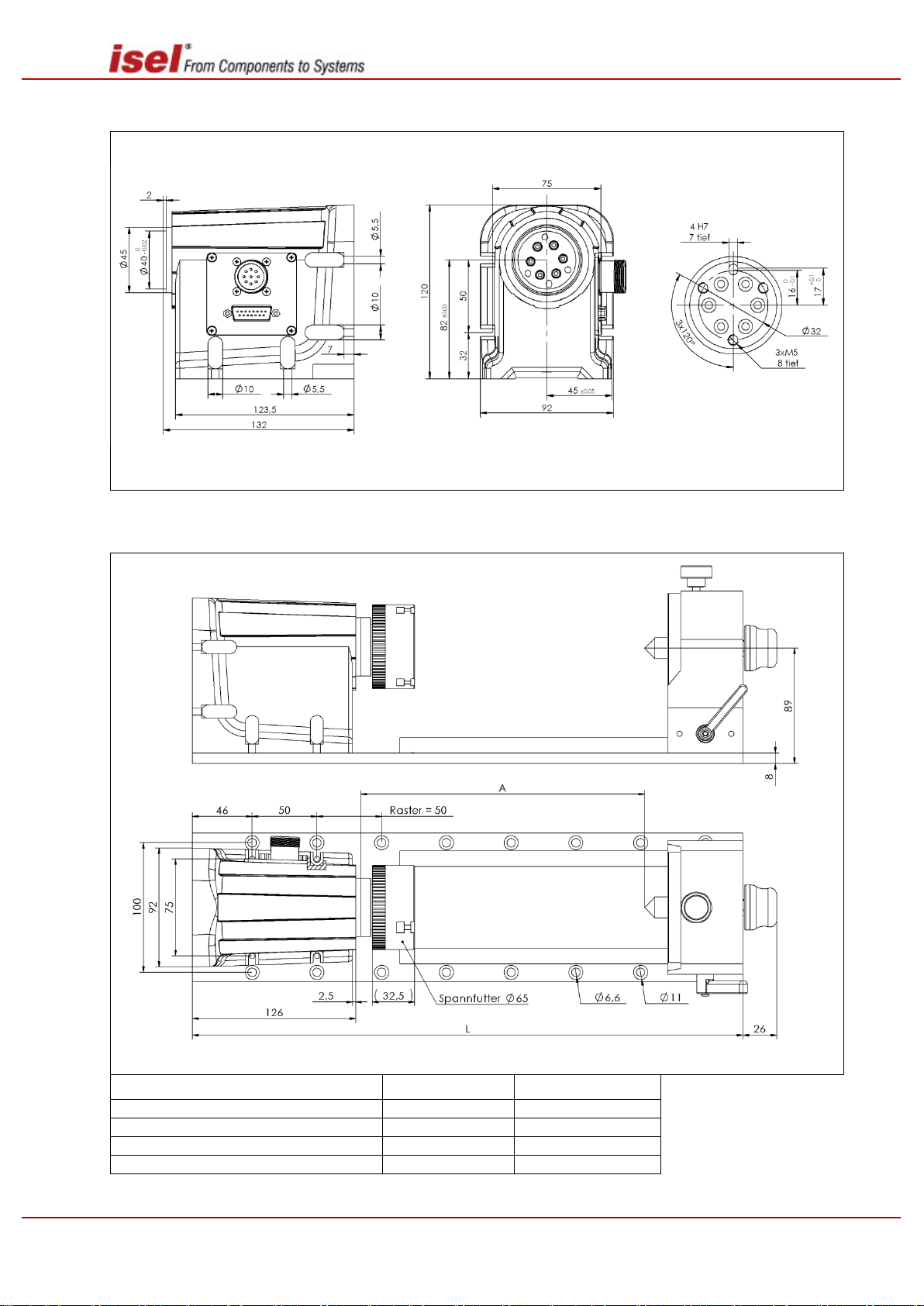
RDH-XS, RDH-S, RDH-M, DSH-S
*Raster = grid / Spannfutter = chuck
Options L A
Tailstock unit RE-XS 200 mmm
325
117
Tailstock unit RE-XS 300 mmm
425
217
Tailstock unit RE-XS 400 mmm
525
317
Tailstock unit RE-XS 500 mmm
625
417
Dimension sheetfor RDH-XS
Dimension sheet for RDH-XS tailstock unit RE XS
13 / 44 April 2019
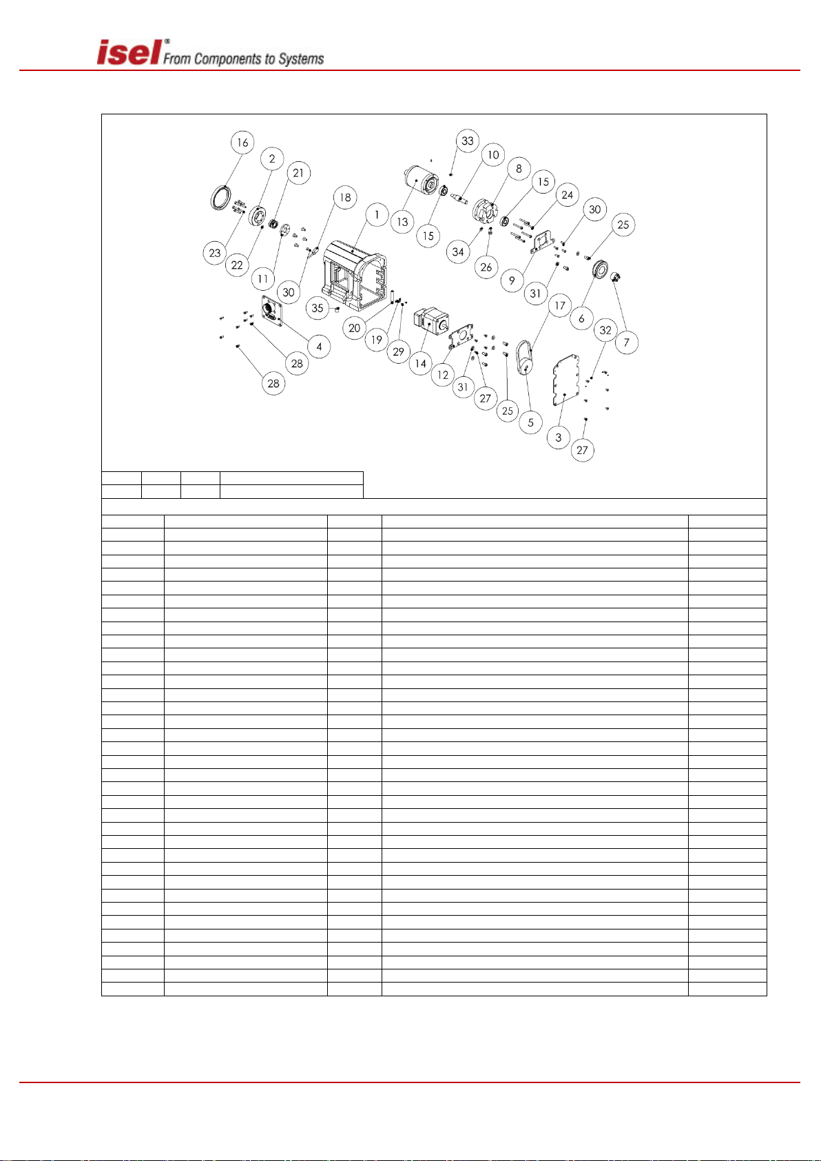
Explodedview RDH-XS
18
30
34
Servo motorstructure
19
20
22
multiphasemotorstructure
Item list RDH-XS
Pos No.
Item number
Quantity
Name
Drawing no. 1 660500 0000
1
EZ4150 - base body - XS - processed
EZ4150
2
660500 4152
1
EZ4152 – Adapter flange XS
EZ4152 3 660500 4156
1
EZ4156 – Cover at back
EZ4156
4
660500 28782 / 660500 28783
1
DZ2878 - Connector panel - RDH-XS
DZ2878
5
660500 41582 / 660500 41583
1
EZ4158 - toothed belt disk HTD3 - Z40
EZ4158
6
660500 39432
1
EZ4159 - toothed belt disk HTD3 - Z40 with flanged wheel
EZ4159 7 898081 8201
1
Clampingbushing 8-18-11(Mädler 615708 00)
8
660500 4153
1
EZ4153 - Transmission attachment
EZ4153 9 660500 4154
1
EZ4154 - Transmission mounting
EZ4154
10
660500 4155
1
EZ4155 – Shaft Transmission entry
EZ4155
11
660500 4164
1
EZ4164 - Clamping ring
EZ4164
12
660500 41512 / 660500 41511
1
EZ4151 - Motor mounting
EZ4151
13
660500 1000 /650200 0010
1
Harmonic Drive Motor HDUC-14-xx-1U-CC (i=100 / i=50)
14
XXXXXX XXXX *
1
Motor module
15
896010 8224
2
Single-row groove ball bearings with sealing pads 608-2RS1
16
843400 0030
1
Shaft seal BABSL 45-58-7 Simrit 72 NBR902
17
616504 0722
1
Toothed belt HTD 3M CXP b=6 L216 (Z=72)
18
562015 4000
1
Inductive proximity switch Baumer IFFM08P37A6_L
19
582132
1
Magneticsensormounting
20
563005
1
Magneticsensor
21
898120 1218
1
Spieth pressure sleeve AK 12-18 L12
22
632501 0002
1
Neodymium block magnet 3 mm
23
891101 0161
6
Pan head screw DIN 912 8.8 VZ M3 x 16
24
891101 0251
6
Pan head screw DIN 912 8.8 VZ M3 x 25
25
891102 0081
6
Pan head screw DIN 912 8.8 VZ M4 x 8
26
891053 0101
1
Allen screw DIN 933 M5x10
27
891191 0065
10
Countersunk screw DIN 965 4.8 VA M 3 x 6
28
891191 0085
8
Countersunk screw DIN 965 4.8 VA M 3 x 8
29
891530 0051
2
Self-tapping screw DIN 7981 VZ 2,2 x 4,5
30
891131 0101
5
Countersunk screw DIN 7991 M 3 x 10
31
893051 0001
6
Disk DIN 125 ST 4,3
32
891378 0025
4
Grubscrew DIN 913 VA M 2 x 2
33
891371 0041
2
Grubscrew DIN 913 M 3 x 4
34
891373 0051
1
Grubscrew DIN 913 M 5 x 5
35
891375 0085
1
Grubscrew DIN 913 VA M 8 x 8
RDH-XS, RDH-S, RDH-M, DSH-S
* Item number see page 26
14 / 44 April 2019

RDH-XS, RDH-S, RDH-M, DSH-S
*Abtriebsflansch = outputflangeHohlwelle = hollowshaft tief = deep
Zentrieransatz Gehäuse = centeringspigotcasing Lochkreis = boltcircle
*Raster = grid / Spannfutter = chuck
Options L A
Tailstock unit RE-S 200 mm
370
128
Tailstock unit RE-S 300 mm
470
228
Tailstock unit RE-S 400 mm
570
328
Tailstock unit RE-S 500 mm
670
428
Dimension sheet for RDH-S
Dimension sheet for RDH-S tailstock unit RE S
15 / 44 April 2019

Exploded view RDH-S - Solid shaft
11
13
14
23
Servo motorstructure
12
21
27 multiphasemotorstructure
Item list RDH-S - Solid shaft
Pos No.
Item number
Quantity
Name
Drawing no.
1
660500 0001
1
EZ3937 - basebody - 14
EZ3937 2 660500 3930
1
EZ3930 - Adapter flange - 14
EZ3930 3 660500 3932
1
EZ3932 - Motor adapter_14
EZ3932
4
660500 39331 / 660500 39332
1
EZ3933 - Motor adapter 14
EZ3933
5
660500 39454 / 660500 39452
1
EZ3945 - Couplingpart
EZ3945 6 660500 39382
1
EZ3938 - Cover - below
EZ3938
7
660510 3919 / 660510 39191
1
EZ3919 - Cover
EZ3919 8 893400 0027
1
Shaft seal BABSL 90-70-7 Simrit 72 NBR902
9
665330 1000 / 650200 0002
1
HarmDrive Motor HFUS-14-xx-2UH (i=101 / i=51)
10
XXXXXX XXXX *
Motor module
11
632501 0002
1
Neodymium Block magnet 3 mm
12
562015 4000
1
Inductive proximity switch Baumer IFFM08P37A6_L
13
660510 3934
1
EZ3934 - Magneticswitchmounting
14
563005
1
Magneticsensor
15
891101 0105
8
Pan head screw DIN 912 8.8 VA M3 x 10
16
891101 0101
8
Pan head screw DIN 912 8.8 VZ M3 x 10
17
891101 0301
8
Pan head screw DIN 912 8.8 VZ M3 x 30
18
891191 0065
10
Countersunk screw DIN 965 4.8 VA M 3 x 6
19
891191 0061
4
Countersunk screw DIN 965 4.8 VZ M 3 x 6
20
891191 0085
4
Countersunk screw DIN 965 4.8 VA M 3 x 8
21
891191 0101
1
Countersunk screw DIN 965 4.8 VZ M 3 x 10
22
891192 0085
4
Countersunk screw DIN 965 4.8 VA M 4 x 8
23
891541 0095
1
Self-tapping screw DIN 7982 VA 2,9 x 9,5
24
891371 0031
3
Grubscrew DIN 913 M 3 x 3
25
891371 0035
4
Grubscrew DIN 913 VA M 3 x 3
26
891372 0045
1
Grubscrew DIN 913 VA M 4 x 4
27
891373 0061
1
Grubscrew DIN 913 M 5 x 6
RDH-XS, RDH-S, RDH-M, DSH-S
* Item number see page 26
16 / 44 April 2019

RDH-XS, RDH-S, RDH-M, DSH-S
17
19
20
30
Servo motorstructure
18
28
35 multiphasemotorstructure
Item list RDH-S - Hollow shaft
Pos
No.
Item number
Quantity
Name
Drawing
no.
1
660500 0001
1
EZ3937 basebody - 14
EZ3937
2
660500 3931
1
EZ3931 Adapter flange - 14 Hollow shaft
EZ3930
3
660500 39381
1
EZ3938 Cover - below hollow shaft structure
EZ3938
4
660510 3919
1
EZ3919-3 Cover - Connector - Option Sub-D 15
EZ3919 5 660500 3944
1
EZ3944 Toothed belt disk HTD3 - Z34
EZ3944
6
660510 3957 / 660510 39431
1
Toothed belt disk HTD3 - Z34 with flanged wheel
7 660500 3941
1
EZ3941 Flange - Pipe seal_14
EZ3941
8
660500 3956
1
EZ3956 Bearing for RE40 Maxon Motor - 14
EZ3956
9
660500 3958 / 660500 3942
1
Motor mounting
EZ3942
10
660500 3940
1
EZ3940 Internal pipe
EZ3940
11
893400 0027
1
Shaft seal BABSL 90-70-7 Simrit 72 NBR902
12
893400 0028
1
Shaft seal BABSL 12-22-6 Simrit 72 NBR902
13
616504 0660
1
Toothed belt CXP HTD 180 -3M - 6 (Z60)
14
896010 6194
1
Single-row groove ball bearings with sealing pads 626-2RS1
15
665330 1000 / 650200 0002
1
HarmDrive Motor HFUS-14-xx-2UH (i=101 / i=51)
16
XXXXXX XXXX *
1
Motor module
17
632501 0002
1
Neodymium Block magnet 3 mm
18
562015 4000
1
Inductive proximity switch Baumer IFFM08P37A6_L
19
660510 3934
1
EZ3934 Magneticswitchmounting
EZ3934
20
563005
1
Magneticsensor
21
891101 0061
6
Pan head screw DIN 912 8.8 VZ M3 x 6
22
891101 0251
8
Pan head screw DIN 912 8.8 VZ M3 x 25
23
891101 0105
8
Pan head screw DIN 912 8.8 VA M3 x 10
24
891102 0101
4
Pan head screw DIN 912 8.8 VZ M4 x 10
25
891191 0065
10
Countersunk screw DIN 965 4.8 VA M 3 x 6
26
891191 0085
8
Countersunk screw DIN 965 4.8 VA M 3 x 8
27
891191 0081
6
Countersunk screw DIN 965 4.8 VZ M 3 x 8
28
891191 0101
1
Countersunk screw DIN 965 4.8 VZ M 3 x 10
29
891192 0085
4
Countersunk screw DIN 965 4.8 VA M 4 x 8
30
891541 0095
1
Self-tapping screw DIN 7982 VA 2.9 x 9.5
31
893050 0001
6
Disk DIN 125 ST 3.2
32
893051 0001
4
Disk DIN 125 ST 4.3
33
891371 0031
3
Grubscrew DIN 913 M 3 x 3
34
891371 0035
4
Grubscrew DIN 913 VA M 3 x 3
35
891373 0061
1
Grubscrew DIN 913 M 5 x 6
Exploded view RDH-S - Hollow shaft
* Item number see page 26
17 / 44 April 2019

RDH-XS, RDH-S, RDH-M, DSH-S
*Abtriebsflansch = outputflange Hohlwelle = hollowshaft tief = deep
Zentrieransatz Gehäuse = centering spigot casing Lochkreis = boltcircle
*Raster = grid / Spannfutter = chuck
Options L A
Tailstock unit RE-M 1000 mmm
1110
624.5
Tailstock unit RE-M 1500 mmm
1610
1124.5
Tailstock unit RE-M 2000 mmm
2110
1624.5
Dimension sheet for RDH-M
Dimension sheet for RDH-M tailstock unit RE M
18 / 44 April 2019

Exploded view RDH-M - Solid shaft
14
15
16
25
Servo motor structure
17
23
31 Multiphase motor structure
Item list RDH-M - Solid shaft
Pos No.
Item number
Quan-
tity
Name
Drawing no.
1
660510 0001
1
EZ3917 - basebody - 25
EZ3917
2
660510 3909
1
EZ3909 - Adapter flange 25
EZ3909
3
660510 3905
1
EZ3905 - Motor mounting 1
EZ3905
4
660510 3906
1
EZ3906 - Motor mounting 2
EZ3906
5
660510 1158
1
EZ1158 - Coupling part for HD motor - Male collet
EZ1158
6
635003 1101 / 635003 1200
1
EZ1160 - Collet Type S
EZ1160
7
660510 39182
1
EZ3918 - Cover - below option Standard
EZ3918
8
660510 3919 /660510 39191
1
EZ3919 - Cover - Connector
EZ3919
9
660510 39072 / 660510
39074 / 660510 39075
1
EZ3907 - Motor adapter
EZ3907
10
66051039253 / 660510
1
EZ3925 - Adapter - Motor shaft
EZ3925
11
893400 0025
1
Shaft seal BABSL 130-150-7.5 Simrit 72 NBR902
12
660510 1000 / 660510 1001
1
HarmDrive Motor HFSU-14-xx-2UH (i=101 / i=51)
13
XXXXXX XXXX *
1
Motor module
14
632501 0002
1
Neodymium Block magnet 3 mm
15
660510 3934
1
EZ3934 – Magneticswitch mounting
EZ3934
16
563005
1
Magneticsensor
17
562015 4000
1
Inductiveproximityswitch
18
891102 0101
8
Pan head screw DIN 912 8.8 VZ M4 x 10
19
891102 0141
4
Pan head screw DIN 912 8.8 VZ M4 x 14
20
891102 0255
16
Pan head screw DIN 912 8.8 VA M4 x 25
21
891191 0081
6
Countersunk screw DIN 965 4.8 VZ M 3 x 8
22
891191 0085
4
Countersunk screw DIN 965 4.8 VA M 3 x 8
23
891191 0101
1
Countersunk screw DIN 965 4.8 VZ M 3 x 10
24
891192 0085
14
Countersunk screw DIN 965 4.8 VA M 4 x 8
25
891541 0095
1
Self-tapping screw DIN 7982 VA 2.9 x 9
26
891132 0161
4
Countersunk screw DIN 7991 M4 x 16
27
891132 0401
12
Countersunk screw DIN 7991 M4 x 40
28
892023 0002
4
Hexagonal flangenut DIN 934 8 M 4
29
891372 0045
5
Grubscrew DIN 913 VA M 4 x 4
30
891373 0161
1
Grubscrew DIN 913 M 5 x 16
31
895025 0126
1
Grubscrew DIN 6325 d6x 12
RDH-XS, RDH-S, RDH-M, DSH-S
* Item number see page 26
19 / 44 April 2019

RDH-XS, RDH-S, RDH-M, DSH-S
15
16
17
27
Servo motor structure
18
23
30 Multiphase motor structure
Item list RDH-M - Hollow shaft
Pos No.
Item number
Quantity
Name
Drawing no.
1
660510 0001
1
EZ3917 - basebody - 25
EZ3917 2 660510 3915
1
EZ3915 - Adapter flange 25
EZ3915 3 660510 39181
1
EZ3918 - Cover - below option hollow shaft
EZ3918
4
660510 3919 / 660510 39191
1
EZ3919 - Cover Connector
EZ3919
5
660510 3924
1
EZ3924 - Toothed belt disk HTD3 - Z52
EZ3924
6
660510 39233 / 660510 39231
660510 39234
1
EZ3923 - Toothed belt disk HTD3 - Z52 with flanged
wheel
EZ3923
7
660510 3921
1
EZ3921 - Flange - Pipe seal
EZ3921
8
660510 39223 / 66051 39222
1
EZ3922 - Motor mountingplate
EZ3922 9 660510 3920
1
EZ3920 - Internal pipe
EZ3920
10
893400 0025
1
Shaft seal BABSL 130-150-7.5 Simrit 72 NBR902
11
893400 0026
1
Shaft seal BABSL 25-35-6 Simrit 72 NBR902
12
616510 0267
1
Toothed belt CXP HTD 267 -3M - 9 (Z89)
13
660510 1001 / 660510 1000
1
HarmDrive Motor HFSU-14-xx-2UH (i=101 / i=51)
14
XXXXXX XXXX *
1
Motor module
15
632501 0002
1
Neodymium Block magnet 3 mm
16
660510 3934
1
EZ3934 - Magneticswitchmounting
EZ3934
17
563005
1
Magneticsensor
18
562015 4000
1
Inductive proximity switch Baumer IFFM08P37A6_L
19
891101 0141
6
Pan head screw DIN 912 8.8 VZ M3 x 14
20
891102 0255
16
Pan head screw DIN 912 8.8 VA M4 x 25
21
891103 0145
4
Pan head screw DIN 912 8.8 VZ M5 x 14
22
891191 0085
8
Countersunk screw DIN 965 4.8 VA M 3 x 8
23
891191 0101
1
Countersunk screw DIN 965 4.8 VZ M 3 x 10
24
891192 0085
14
Countersunk screw DIN 965 4.8 VA M 4 x 8
25
891122 0351
12
Pan head screw DIN 6912 8.8 M 4 x 35
26
891132 0161
4
Countersunk screw DIN 7991 M 4 x 16
27
891541 0095
1
Self-tapping screw DIN 7982 VA 2.9 x 9.5
28
893053 0001
4
Disk DIN 125 ST 5.3
29
892023 0002
4
Hexagonal flangenut DIN 934 8 M 4
30
895025 0126
1
Grubscrew DIN 6325 d6x 12
31
891372 0045
5
Grubscrew DIN 913 VA M 4 x 4
32
891373 0161
1
Grubscrew DIN 913 M 5 x 16
Exploded view RDH-M - Hollow shaft
* Item number see page 26
20 / 44 April 2019

Dimension sheet for RSH-S
*Schritt = steppermotorSchwenkbereich = turingarea tief = deep
Servo = servomotor Grundplatte = baseplate
Item list RDH-S - Hollow shaft
Pos
No.
Item number
Quan-
tity
Name
Drawing no.
1 / 1
R5H-S Counter bearing
/
2 / 1
R5H-S Swivel unit
/
3 / 1
Rotary indexing table RDH-S (for RSH-S)
/
RDH-XS, RDH-S, RDH-M, DSH-S
Exploded view DSH-S
21 / 44 April 2019

RDH-XS, RDH-S, RDH-M, DSH-S
Item list R5H-S Counter bearing
Pos No.
Item number
Quan-
tity
Name
Drawing no.
1
665320 4331
1
EZ4331 Counter bearing block - S
EZ4331
2
665320 4385
1
EZ4385 Cover Counter bearing - S
EZ4385 3 665320 4369
1
EZ4369 Mount for counter bearing block - S
EZ4369
4
893400 0026
1
Shaft seal BABSL 25-35-6 Simrit 72 NBR902
5 1
Needle bearings NKI 20-16
6
891104 0205
5
Pan head screw DIN 912 8.8 VA M6 x 20
7 891054 0201
2
Allen screw DIN 933 M6x20
8
891190 0045
1
Countersunk screw DIN 965 4.8 VA M 2.5 x 4
9
891191 0065
2
Countersunk screw DIN 965 4.8 VA M 3 x 6
Exploded view R5H-S Counter bearing
22 / 44 April 2019

RDH-XS, RDH-S, RDH-M, DSH-S
4
20
22
41
Servo motor structure
21
37
Multiphase motor structure
Item list RDH-S (for Swivel unit RSH-S)
Pos No.
Item number
Quantity
Name
Drawing
no.
1
660500 0012
1
DZ2869 - Processing RSH-S - Servo
DZ2869 2 665320 28681
1
DZ2868 - Connector - RSH-S
DZ2868 3 660500 3931
1
EZ3931 Adapter flange - 14 Hollow shaft
EZ3930
4
660510 3934
1
EZ3934 Magnetic switch mounting
EZ3934
5
660500 39382
1
EZ3938 Cover - below Standard option
EZ3938 6 660500 3944
1
EZ3944 Toothed belt disk HTD3 - Z34
EZ3944 7 660500 3956
1
Bearing for motor module
8
660500 3957 /660500 39431
1
Toothed belt disk HTD3 - Z34 with flanged wheel for motor module
EZ3957
9
660500 3958 / 660500 3942
1
EZ3958 Motor adapter hollow shaft motor module
EZ3958
10
665320 42511
1
EZ4251-4 Stopcollar - right
EZ4251
11
See table
1
EZ4252 Internal pipe_14 Axis combinationL=112.5
EZ4252
12
665320 4256
1
EZ4256 Limit switch module ring LS
EZ4256
13
665320 4257
2
EZ4257 Adjustment ring LS with control disk
EZ4257
14
665320 4258
2
EZ4258 Control disk
EZ4258
15
665320 4259
1
EZ4259 Divider plate
EZ5249
16 / 1
EZ4262 Cable fastening
17 / 2
EZ4263 Cable fastening - Pipe
18
XXXXXX XXXX *
1
Motor module
19
665330 1000 / 650200 0002
1
HarmDrive Motor HFSU-14-xx-2UH (i=101 / i=51)
20
632501 0002
1
Neodymium block magnet 3 mm
21
562015 4000
1
Inductive proximity switch Baumer IFFM08P37A6_L
22
563005
1
Magnetic sensor
23
896010 6194
1
Single-row groove ball bearings with sealing pads 626-2RS1
24
893400 0027
1
Shaft seal BABSL 90-70-7 Simrit 72 NBR902
25
616504 0660
1
Toothed belt CXP HTD 180 -3M - 6 (Z60)
26
665320 0001
2
Fork light barrier PM-T54P
27
891371 0035
4
Grub screw DIN 913 VA M 3 x 3
28
891373 0061
1
Grub screw DIN 913 M 5 x 6
29
89114x 0061
4
Pan head screw DIN 84 4.8 VG M 2 x 6
30
891101 0061
6
Pan head screw DIN 912 8.8 VZ M3 x 6
31
891101 0081
4
Pan head screw DIN 912 8.8 VZ M3 x 8
32
891101 0105
8
Pan head screw DIN 912 8.8 VA M3 x 10
Exploded view RDH-S (for swivel unit)
23 / 44 April 2019

33
891101 0251
8
Pan head screw DIN 912 8.8 VZ M3 x 25
34
891102 0101
4
Pan head screw DIN 912 8.8 VZ M4 x 10
35
891191 0065
10
Countersunk screw DIN 965 4.8 VA M 3 x 6
36
891191 0081
6
Countersunk screw DIN 965 4.8 VZ M 3 x 8
37
891191 0101
1
Countersunk screw DIN 965 4.8 VZ M 3 x 10
38
891122 0251
4
Pan head screw DIN 6912 A2 M 4 x 25
39
891591 0101
2
Roundhead screw DIN 7380 M 3 x 10
40
891592 0101
2
Roundhead screw DIN 7380 M 4 x 10
41
891541 0095
1
Self-tapping screw DIN 7982 VA 2.9 x 9.5
42
893050 0001
6
Disk DIN 125 ST 3.2
43
893051 0001
4
Disk DIN 125 ST 4.3
44
891132 0085
2
Countersunk screw DIN 7991 VA, M 4 x 8
* Item number see page 26
10
16
18
36
Servo motor structure
17
32
41 Multiphase motor structure
Exploded view R5H-S Swivel unit
RDH-XS, RDH-S, RDH-M, DSH-S
24 / 44 April 2019

RDH-XS, RDH-S, RDH-M, DSH-S
Item list for R5H-S Swivel unit
Pos No.
Item number
Quan-
tity
Name
Drawing
no.
1
665320 4340
1
EZ4340 Pin fixing
EZ4340
2
665320 4343
1
EZ4343 Base body - Cover for Swivel unit - S
EZ4343 3 665320 4345
1
EZ4345 Divider plate - S
EZ4345
4
660500 3956
1
EZ4357 Bearing for motor module
EZ3956
5
665320 4366
1
EZ4366 Flange - S Drive side
EZ4366 6 665320 4367
1
EZ4367 Flange - S Counter bearing side
EZ4367
7
665320 4375
1
EZ4375 Base body Swivel unit - S Finishing
EZ4375 8
1
EZ4384 Cover Swivel unit - S
EZ4384 9 660500 3930
1
EZ3930 - Adapter flange - 14
EZ3930
10
660510 3934
1
EZ3934 Magnetic switch mounting
EZ3934
11
660500 3944
1
EZ3944 Toothed belt disk HTD3 - Z34
EZ3944
12
660500 3957
1
Toothed belt disk HTD3 - Z34 with flanged wheel for motor
module
EZ3957
13
660500 3958
1
EZ3958 Motor adapter hollow shaft motor module
EZ3958
14
XXXXXX XXXX *
1
Motor module
15
665330 1000 / 650200 0002
1
HarmDrive Motor HFSU-14-xx-2UH (i=101 / i=51)
16
632501 0002
1
Neodymium block magnet 3 mm
17
562015 4000
1
Inductive proximity switch Baumer IFFM08P37A6_L
18
563005
1
Magnetic sensor
19
896010 6194
1
Single-row groove ball bearings with sealing pads 626-2RS1
20
893400 0027
1
Shaft seal BABSL 90-70-7 Simrit 72 NBR902
21
616504 0660
1
Toothed belt CXP HTD 318 -3M - 6 (Z106)
22 1
Pipe D10 d5 L=40
23
890365 0101
1
TE2770-4 Grubscrew M8x0.75 with 60 point
TE2770
24
891371 0031
3
Grubscrew DIN 913 M 3 x 3
25
891101 0061
6
Pan head screw DIN 912 8.8 VZ M3 x 6
26
891101 0105
8
Pan head screw DIN 912 8.8 VA M3 x 10
27
891101 0251
8
Pan head screw DIN 912 8.8 VZ M3 x 25
28
891101 0305
2
Pan head screw DIN 912 8.8 VA M3 x 30
29
891102 0061
2
Pan head screw DIN 912 8.8 VZ M4 x 6
30
891103 0125
3
Pan head screw DIN 912 8.8 VA M5 x 12
31
891191 0081
6
Countersunk screw DIN 965 4.8 VZ M 3 x 8
32
891191 0101
1
Countersunk screw DIN 965 4.8 VZ M 3 x 10
33 16
Pan head screw DIN 6912 A2 M 3 x 6
34
891122 0101
3
Pan head screw DIN 6912 8.8 M 4 x 10
35
891122 0101
16
Pan head screw DIN 6912 A2 M 4 x 10
36
891541 0095
1
Self-tapping screw DIN 7982 VA 2.9 x 9.5
37
891132 0451
1
Countersunk screw DIN 7991, M 4 x 45
38
893050 0001
6
Disk DIN 125 ST 3.2
39
893050 0005
16
Disk DIN 125 ST 3.2
40
893051 0001
3
Disk DIN 125 ST 4.3
41
895024 0126
1
Grubscrew DIN 6325 d5x 12
42
895025 0126
2
Grubscrew DIN 6325 d6x 12
* Item number see page 26
25 / 44 April 2019

RDH-XS, RDH-S, RDH-M, DSH-S
Drive module
RDH-XS
RDH-S
RDH-M
RSH-S
Item no.
multiphase-
motor
MS-045 HT
X X X 398702 0002
MS-200 HT
X 398701 0002
EC
servo-
motor
EC 42 (brushless)
X X X 398703 0005
EC 60S (brushless)
X 398703 0003
DC servo-
motor
RE 40 (brushed)
X X X 398700 0001
DC 100 (brushed)
X 398700 0012
Drive module
Various drive modules with multiphase motors, brushed servo motors (BDC) and brushless servo motors
(BLDC) are available for the rotary units RDH - RSH as standard.
26 / 44 April 2019

RDH-XS, RDH-S, RDH-M, DSH-S
Motor connector
M23 9-pol. (8+1) pin
Encoder connector
Sub-D 15-pin Pin
View of pin insertion
on the plug-in side
1
Motor phase U
2
Motor phase V
3
Motor phase W
4
---
5
+24V brake
6
GND brake
7
8
9
Protectiveconductor
PE
Casing – cableshield
View of pin insertion
on the plug-in side
1
Hall signal A
2
+5V encoder/Hall
3
Encoder track /Z
4
Encoder track /B
5
Encoder track /A
6
+24V Switch
7
Limit switch 1
8
GND switch
9
Hall signal B
10
GND encoder
11
Encoder track Z
12
Encoder track B
13
Encoder track A
14
Hall signal C
15
Limit switch 2
Casing – cableshield
Motor connector
M23 9 pin (8+1) pin
Encoder connector
D-sub 15 pin
View of pin insertion
on the plug-in side
1
Motor phase U
2
Motor phase V
3
Motor phase W
4
+24 V brake
5
GND brake
6
Protective earth PE
Housing - cable shield
View of pin insertion
on the plug-in side
1
Hall signal A
2
+5 V encoder/Hall
3
Encoder track /Z
4
Encoder track /B
5
Encoder track /A
6
+24 V switch
7
Limit switch 1
8
GND switch
9
Hall signal B
10
GND encoder
11
Encoder track Z
12
Encoder track B
13
Encoder track A
14
Hall signal C
15
Limit switch 2
Housing - cable shield
Motor connector
M23 12 pin Pin
View of pin insertion
on the plug-in side
1
Motor phase 1A
2
Motor phase 1B
3
Motor phase 2A
4
Motor phase 2B
5
+24V Switch
6
+24V brake
7
GND switch
8
GND brake
9
Limit switch 1
10
Limit switch 2
11
---
12
---
Casing – cableshield
2.3 Connector pin assignment for rotary units
Connector pin assignment for brushless DC servo motors (BLDC) 48V
Connector pin assignment for brushless DC servo motors (BLDC) 48 V, 400W
Connector pin assignment for M23 12 pin for multiphase motors
27 / 44 April 2019

RDH-XS, RDH-S, RDH-M, DSH-S
3 Commissioning, general information
The rotary unit is commissioned after mounting the relevant drive modules and any necessary cables.
Follow the relevant instructions in the documentation of the motor modules, output stages or controls
used.
Procedure:
Switch off the controls and ensure that they are secured.
Mount the rotary unit / rotary-swivel unit securely to a suitable work surface
Connect the encoder cable.
Connect the motor cable.
Switch the controls on and check that the rotary unit / rotary-swivel unit is working correctly
Conduct a test run
- First with slow movement,
- Then under operating conditions
Incorrect assembly (including loading on the axis system), cabling or commissioning
increases the risks.
Unauthorized individuals should not be given access to the controls or the switch cabinet.
There is a risk of electric current causing injuries. This is the responsibility of the individual
who installed the machinery.
28 / 44 April 2019

RDH-XS, RDH-S, RDH-M, DSH-S
A: Alignmentsurface
B: Free-stationary
C: Rack mounting
4 Assembly of the rotary unit
Before you can assemble your new rotary unit, you must remove any securing devices used in transport.
4.1 Mounting and adjustment instructions
You have several options for mounting the components individually:
A) Alignment surface
The rotary units RDH / RSH have a stop face on the connector side of the casing with a clearly defined
distance from the axis of rotary. (Distances are given in the respective dimensioned drawings).
In addition, the rotary units have two plane installation surfaces parallel to the axis of rotary, which allows
the rotary unit to be used as a rotary axis as well as a rotary indexing table.
B) Free-stationary rotary unit
You can place the rotary unit on a rack, a work table or any other suitable, i.e. sturdy base.
Choose the location carefully so that the product cannot fall or be knocked over by
any impact or tug on the cables.
C) Rack mounting (recommended)
Use the depression in the base body of the rotary unit to mount the rotary unit on your rack. Use appropriate Pan head screws and the matching T-nuts / threaded rails (accessories) to secure it.
Make sure the mounting surfaces are sufficiently clean.
The base bodies used in the rotary units are castings which can deviate in terms of their tolerance as a
result of the manufacturing process.
The surface areas of these base bodies are plane-milled to achieve a high degree of precision.
However, to achieve the desired guide accuracies and running performance, the rotary unit must either
be laid out over an appropriately flat surface or arranged over levelling plates. This achieves round tolerances or axial run-out tolerances of maximum 0.03 mm in the Transmission flange.
Make sure the fixing surfaces are sufficiently clean and sufficiently level.
29 / 44 April 2019

RDH-XS, RDH-S, RDH-M, DSH-S
A: Mounting tailstock unit RE M / RE S
B: Mounting tailstock unit RE XS
4.2 Mounting the tailstock unit
A) Position both guide shafts of the tailstock unit RE S / RE M in the two through bores of the rotary unit
RDH-S / RDH-M so that these can be secured on the underside of the rotary unit with the appropriate
grubscrews.
For tailstock unit RE M, place the guide shafts (facing the rotary unit) in a middle position between the
rotary unit and the pinole. Secure the two guide shafts to the work surface with suitable screws.
Secure the position of tailstock unit RE S by also screwing the base plate of the tailstock unit to the work
surface.
B) First secure rotary unit RDH-XS to the base plate of the tailstock unit (4x M5). Leave the screws loose
at this stage. Turn the rotary unit axial to the tailstock unit and tighten the screws securely.
Now secure the entire unit to your work surface (if you are using T-nut plates use T-nus and the
appropriate matching screws, see accessories). Leave the screws loose at this stage. Align the unit
precisely with the existing axis system and secure the screws.
30 / 44 April 2019

5 Fault list
Problem/fault
Possible cause(s)
Help
Louder running
sounds
Dirt
Lack of lubricating film
Clean the rotary unit
in the area around the seals
Stiffness
Dirt
Incorrect tension
Clean the rotary unit
Alignment, adjustment
Impaired positioning
accuracy or
repeatability
Overload
Reduce load
Important: In unfavourable electromagnetic conditions the effects of EMC can cause faults.
Only allow qualified technicians to carry out repairs on the electric components of the product.
Otherwise there is a risk of electric current causing fatal injuries.
RDH-XS, RDH-S, RDH-M, DSH-S
Do not attempt to manipulate the controller or output stage of the rotary unit.
31 / 44 April 2019

6 Technical specification
Technical specification RDH-XS
Multiphase motor
MS 045HT*
EC servo motor
EC 42
DC servo motor
RE 40
Reduction ratio
1 : 50
1 : 100
1 : 50
1 : 100
1 : 50
1 : 100
Nominal output speed [rpm]
5 2 22
11
22
11
at 1500 Hz (225 rpm)
at 1100 rpm
at 1100 rpm
Max. output speed
[rpm]
24
12
59
30
70
35
at 8000 Hz (1200 rpm)
--
Nominal torque
[Nm]
5
7 5 7 5 7
at 1500 Hz (225 rpm)
--
Max. Torque(short)
[Nm]
--
-- 5 7 5 7
Nominal holding torque (static load)
[Nm] 5 7 5 7 5 7
Max drive load
[Nm]
9
14 9 14 9 14
Limit for repeatable peak torque
Dynamic loading capacity C
[N]
392
Static loading capacity C
0
[N]
392
Weight
[Kg]
2.3
* Values for half-step-
ping mode
Technical specification
RDH-S
Multiphase motor
MS 045HT*
EC servo motor
EC 42 (brushless)
DC servo motor
RE 40 (brushed)
Reduction ratio
1 : 51
1 : 101
1 : 51
1 : 101
1 : 51
1 : 101
Nominal output speed
[rpm]
4 2 22
11
22
11
at 1500 Hz (225 rpm)
at 1100 rpm
at 1100 rpm
Max. output speed
[rpm]
24
12
59
30
69
35
at 8000 Hz
--
Nominal torque
[Nm]
7
11
4.8
9.2
4.6
9
at 1500 Hz
--
Max. Torque (short-term)
[Nm]
--
-- 7 11 7 11
Nominal holding torque (static load)
[Nm] 7 11 7 11 7 11
Max driveload
[Nm]
18
28
18
28
18
28
Limit for repeatable peak torque
Dynamic loading capacity C
[N]
5800
Static loading capacity C0
[N]
8600
Weight
[Kg]
4.6
* Values for half-step-
ping mode
6.1 Mechanical data
RDH-XS, RDH-S, RDH-M, DSH-S
32 / 44 April 2019

RDH-XS, RDH-S, RDH-M, DSH-S
Technical specification
RDH-M
Multiphase motor
MS 200HT*
EC servo motor
EC 60S (brushless)
DC servo motor
DC 100 (brushed)
Reduction ratio
1 : 51
1 : 101
1 : 51
1 : 101
1 : 51
1 : 101
Nominal output speed
[rpm]
4 2 22
11
22
11
at 1500 Hz (225 rpm)
at 1100 rpm
at 1100 rpm
Max. output speed
[rpm]
24
12
59
30
59
30
at 8000 Hz
--
--
Nominal torque
[Nm]
24
46 9 17 7 14
at 1500 Hz
--
--
Max. Torque (short-term)
[Nm]
--
--
42
80
39
73
Nominal holding torque (static load)
[Nm]
55
108
26
51
15
30
Max drive load
[Nm]
98
157
98
157
98
157
Limit for repeatable peak torque
Dynamic loading capacity C
[N]
21800
Static loading capacity C
0
[N]
35800
Weight
[Kg]
13,7
* Values for half-step-
ping mode
Technical specification
RSH-S
Multiphase motor
MS 045HT*
EC servo motor
EC 42
DC servo motor
RE 40
Reduction ratio
1 : 51
1 : 101
1 : 51
1 : 101
1 : 51
1 : 101
Nominal output speed
[rpm]
4 2 22
11
22
11
at 1500 Hz (225 rpm)
at 1100 rpm
at 1100 rpm
Max. output speed
[rpm]
24
12
59
30
69
35
at 8000 Hz
--
Nominal torque
[Nm]
7
11
4.8
9.2
4.6
9
at 1500 Hz
--
Max. Torque (short-term)
[Nm]
--
-- 7 11 7 11
Nominal holding torque (static load)
[Nm] 7 11 7 11 7 11
Max drive load
[Nm]
18
28
18
28
18
28
Limit for repeatable peak torque
Dynamic loading capacity C
[N]
5800
Static loading capacity C
0
[N]
8600
Weight
[Kg]
12
* Values for half-step-
ping mode
33 / 44 April 2019

RDH-XS, RDH-S, RDH-M, DSH-S
Transport load, processing forces, feed rate
Rotary unit
1*
2* 3 4 5 6
7
RDH-M (step)
100kg
45kg
55Nm
24Nm
24Nm
4 rpm
1 : 51
RDH-M (step)
160kg
70kg
108Nm
45Nm
45Nm
2 rpm
1 : 101
RDH-M (EC servo/brushless)
110kg
50kg
26Nm
9Nm
9Nm
22 rpm
1 : 51
RDH-M (EC servo/brushless)
180kg
80kg
51Nm
17Nm
17Nm
11 rpm
1 : 101
RDH-M (DC servo/brushed)
110kg
50kg
15Nm
7Nm
7Nm
22 rpm
1 : 51
RDH-M (DC servo/brushed)
180kg
80kg
30Nm
14Nm
14Nm
11 rpm
1 : 101
RDH-S (step)
30kg
15kg
7Nm
7Nm
7Nm
4 rpm
1 : 51
RDH-S (step)
48kg
24kg
11Nm
11Nm
11Nm
2 rpm
1 : 101
RDH-S (EC servo /brushless)
30kg
15kg
7Nm
4.6Nm
4.6Nm
22 rpm
1 : 51
RDH-S (EC servo/brushless)
48kg
24kg
11Nm
4.6Nm
9.2Nm
11 rpm
1 : 101
RDH-S (DC servo/brushed)
25kg
13kg
7Nm
4.6Nm
4.6Nm
22 rpm
1 : 51
RDH-S (DC servo/brushed)
40kg
20kg
11Nm
8.7Nm
8.7Nm
11 rpm
1 : 101
RDH-XS (step)
30kg
10kg
5Nm
5Nm
5Nm
24 rpm
1 : 50
RDH-XS (step)
30kg
10kg
7Nm
7Nm
7Nm
12 rpm
1 : 100
RDH-XS (EC servo/brushless)
30kg
10kg
5Nm
5Nm
5Nm
59 rpm
1 : 50
RDH-XS (EC servo/brushless)
30kg
10kg
7Nm
7Nm
7Nm
30 rpm
1 : 100
RDH-XS (DC servo/brushed)
30kg
10kg
5Nm
5Nm
5Nm
70 rpm
1 : 50
RDH-XS (DC servo/brushed)
30kg
10kg
7Nm
7Nm
7Nm
35 rpm
1 : 100
* Standard values may deviate depending on the application
Performance data for drive bearing
Rotary units RDH
RDH-M
RDH-S /
RSH-S
RDH-XS
Dynamic loading capacity
C
[N]
21800
5800
-
Static loading capacity
C0
[N]
35800
8600
-
Added dynamic breakdown torque
1
M
[Nm]
258
74
5
Added static breakdown torque
2
M0
[Nm]
1070
144
5
Tilting rigidity
Kb
[Nm/arcmin]
114
25
-
Added axial load
3
Fa
[N]
11504
3044
392
Added radial load
3
Fr
[N]
7708
2039
392
1
applies to turning drives
2
applies to stationary drives with static safeguard 1.5
3
is on the basis of a normal load, average rotational speed 15 rpm, working life 15000h
These data only apply for a load
M, M0 Fa=Fr=0
Fa Fr=0, M=0
Fr Fa=0, M=0
working life is calculated similarly to the roller bearings through the dynamic equivalent load, load factors, the average output
speed and the service factor to the load ratings
34 / 44 April 2019

RDH-XS, RDH-S, RDH-M, DSH-S
Maintenance interval
Maintenance work
When necessary
Clean the rotary unit
300 – 700 operating hours
Visual check of seals, attachments
2 years
Replace toothed belts (when available)
Replace shaft seal rings
6.2 Electrical data
You can find the motor data, output stages mains values and connection values and controller data in
the documentation
https://www.isel.com/en/support-downloads/manuals.html
7 Maintenance and cleaning
7.1 Maintenance instructions
The RDH - RSH rotary units function extremely accurately and reliably. Maintenance costs are therefore
relatively low.
Maintenance of the rotary units is limited to cleaning them of coarse dirt particles and contaminants.
The Harmonic Drive Motors are ex works lubricated with special isel grease. No further basic lubrication
is necessary before the axis system is started up.
7.2 Cleaning
Clean the surface of the rotary unit's cast housing and the output flange with a lint-free, dry/slightly damp
cloth. Do not use harsh cleaning agents or abrasive cleaners.
35 / 44 April 2019

RDH-XS, RDH-S, RDH-M, DSH-S
8 Decommissioning / disposal
The symbol on the product or its packaging indicates that the product must not be disposed of with
normal household waste. Users must deliver the products/used devices to a collection point for used
electrical and electronic devices. The separate collection and proper disposal of your products/used
devices helps to conserve natural resources and guarantees recycling, which in turn protects people's
health and the environment. You can get information on where to find collection points for your used
devices from your local borough council, local waste disposal companies or on the Internet.
9 CE Conformity
The rotary units RDH - RSH are classified as 'partly completed machines' according to MD 2006/42/EC
and therefore comply with CE guidelines (see installation explanation of the manufacturer, isel Germany
AG).
As a 'partly completed machine' the product does not carry the CE mark, although it still conforms to the
relevant European guidelines.
isel Germany AG hereby confirms that the product complies with the following directives:
EC Directive 2006/42/EC 'Machinery Directive'
EC Directive 2006/95/EC 'Electrical Equipment Designed for Use within certain Voltage Limits'/'Low
Voltage Directive'
EC Directive 2004/108/EC 'Electromagnetic Compatibility (EMC)'
The installation explanation for the product rotary unit RDH - RSH is an integral part of these assembly
instructions.
36 / 44 April 2019

RDH-XS, RDH-S, RDH-M, DSH-S
10 Service
If you need customer service or have any questions regarding parameterization of the controllers/motor
output stages (if they are included in the scope of the delivery), please consult:
Mr. Frank Hecht (Dermbach - Thüringen plant):
Tel: +49 (0)6659 981-763
Email: support@isel.com
Mr. Frank Jansen (Eichenzell – Hessen plant):
Tel: +49 (0)6659 981-765
Email: support@isel.com
11 Warranty
Warranty:
Over and above the seller's statutory liability for material defects and according to the following conditions, as the manufacturer we guarantee flawless working life of products from isel Germany AG if used
properly.
This guarantee extends to the functioning of isel Germany AG products and includes any fault which can
be proved to have been caused by the manufacturing process or material defects.
Warranty exclusions:
All replaceable individual components, e.g. screws, connecting pins etc. are excluded from this warranty.
Furthermore, we accept no liability for damage caused by:
Inappropriate or improper use
Faulty or negligent handling
Failure to observe installation instructions and instructions on care, as well as modifications or repairs
carried out by users themselves
The effects of chemical and physical influences and improper use on the surface of the materials, e.g.
damage from sharp objects.
We do not accept any liability for consequential damage.
We do not accept any liability for damage to persons and property caused by improper handling or failure
to observe the safety guidelines. In cases such as these no claim can be made against the warranty.
Warranty conditions:
Our warranty only covers at our discretion the repair or replacement of the product free of charge for
first/end users within the warranty period.
Warranty period:
In accordance with our General Terms and Conditions (AGB of isel Germany AG, Section VI) our warranty lasts one year.
For claims please contact the seller or the manufacturer directly, quoting the number of your invoice/delivery note.
Manufacturer:
isel
Germany AG
Bürgermeister-Ebert-Straße 40
D-36124 Eichenzell
Tel.: (06659) 981-700
Fax: (06659) 981-776
E-Mail: automation@isel.com
http://www.isel.com
37 / 44 April 2019

RDH-XS, RDH-S, RDH-M, DSH-S
EN ISO 12100:2010
Safety of Machinery - Safety of machinery -- General principles for design -- Risk
assessment and risk reduction
EN 349:1993+A1:2008
Safety of Machinery - Minimum distances to avoid the Bruising of body parts
EN 60204-1:2006
Safety of machinery. Electrical equipment of machines
- Part 1: General requirements
12 Declaration of incorporation according to MD 2006/42/EC
Installation explanation according to EC Machinery Directive (MD) 2006/42/EC, Appendix II B
The manufacturer isel Germany AG
Bürgermeister-Ebert-Straße 40
D-36124 Eichenzell, Germany
hereby declares that the product (incomplete machine)
Product description: Rotary unit RDH-XS Item number: 26600x 0x00
Rotary unit RDH-S Item number: 2661xx 0x00
Rotary unit RDH-M Item number: 2662xx 0x00
Rotary unit DSH-S Item number: 26541x x000
complies with the fundamental health and safety requirements of EC Machinery Directive 2006/42/EC
Appendix I.
The following harmonised standards were applied:
The following additional EC Directives relevant to this product were applied:
Low Voltage Directive 2014/35/EC
The technical documentation for this incomplete machine was produced according to Appendix VII Part
B. The manufacturer undertakes to pass on these technical documents to national authorities in electronic form on request.
Member of staff responsible for producing the technical documents or assembly instructions/installation
explanation is: Christian Bley (CE coordinator, isel Germany AG)
The product (incomplete machine) is intended for installation into a machine or combining with other
incomplete machines to form a machine as defined in MD 2006/42/EC, Article 1, Section (1) a.
This incomplete machine (product) must not be commissioned until the machine in which this product is
installed or of which it forms a component meets the provisions of all the relevant directives (especially
MD 2006/42/EC) and this (complete) machine carries a CE mark.
Place, date: Dermbach, 21 April 2016
_____________________________
Werner Kister, Member of the Management Board
38 / 44 April 2019

13 Index
RDH-XS, RDH-S, RDH-M, DSH-S
A
Abbreviations ........................................................... 2
Appendix with Accessories ................................. 43
Assembly ................................................................ 29
C
CE Conformity ........................................................ 38
Cleaning .................................................................. 36
Copyright .................................................................. 2
D
Decommissioning .................................................. 37
Deliverables .............................................................. 8
drive elements ........................................................ 10
F
Fault list ................................................................... 31
Functions .................................................................. 9
O
Operating environment ........................................... 6
P
Proper use ................................................................ 8
S
Safety guidelines ..................................................... 6
Service ..................................................................... 39
Symbols used ........................................................... 2
T
Technical specification ......................................... 32
W
Warranty .................................................................. 40
I
Installation instructions .......................................... 9
39 / 44 April 2019

14 Appendix
RDH-XS
Chuck
• 3-jaw chuck Ø 65
Item no.: 269060 4065*
* includingflange
Tailstockunit RE XS
• for RDH-SX
Item no.: 269100 0020 (200mm)
Item no.: 269100 0030 (300mm)
Item no.: 269100 0040 (400mm)
Item no.: 269100 0050 (500mm)
RDH-S
Chuck
• 3-jaw chuck Ø 65
Item no.: 269060 3065*
• 3-jaw chuck Ø 80
Item no.: 269063 2080*
• 3-jaw chuck Ø 100
Item no.: 269063 2100*
Chuck
• 4-jaw chuck Ø 100
Item no.: 269061 2100*
* includingflange
Tailstockunit RE S
• for RDH-SX
Item no.: 269100 1020 (200mm)
Item no.: 269100 1030 (300mm)
Item no.: 269100 1040 (400mm)
Item no.: 269100 1050 (500mm)
RDH-M
Chuck
• 3-jaw chuck Ø 125
Item no.: 269062 2125
• 4-jaw chuck Ø 125
Item no.: 269061 0125*
* including flange
Aluminium T-nut disk
• Ø 240 mm / PT 25
Item no.: 269050 0240
• Ø 365 mm / PT 25
Item no.: 269050 0365
Aluminium rotarydisk
• Ø 490 mm, anchor points
drilled at extra charge on customer request
Item no.: 269051 0500
Tailstock unit RE S
• for RDH-SX
Item no.: 269100 2100
(1000mm)
Item no.: 269100 2150
(1500mm)
Item no.: 269100 2200
(2000mm)
14.1 A1: Accessories
RDH-XS, RDH-S, RDH-M, DSH-S
40 / 44 April 2019

RDH-XS, RDH-S, RDH-M, DSH-S
RSH-S
Chuck
• 3-jaw chuck Ø 65
Item no.: 269060 3065*
• 3-jaw chuck Ø 80
Item no.: 269063 2080*
• 3-jaw chuck Ø 100
Item no.: 269063 2100*
Chuck
• 4-jaw chuck Ø 100
Item no.: 269061
2100*
* includingflange
Rotary table
• Ø 150 mm
Item no.: 269050 0150
Threadedinserts/slidingnut
Item number
Comments
Threadedinsert M6 (Grid 50)
209011
VE 3 piece x 1m
Slidingnut M6
209001 0005
VE 100 pieces
Slidingnut 2x M6
209002 0004
VE 50 pieces
Slidingnut M5
209006 0001
VE 20 pieces
Angled sliding nut 2x M6
209021 0003
VE 25 pieces
Special angled gliding nut 3x M6
209022 0003
VE 25 pieces
14.2 A2: Miscellaneous
Assembly instructions [product] identification no.: 970261 BE 0001 / 11-2011
41 / 44 April 2019

RDH-XS, RDH-S, RDH-M, DSH-S
Space for notes
42 / 44 April 2019

RDH-XS, RDH-S, RDH-M, DSH-S
Space for notes
43 / 44 April 2019

 Loading...