

Page 1

isel Germany AG, D-
36124 Eichenzell,
Opera
-Ebert-Str. 40 (06659)981-0
IT116 flash
IT116 mini
(06659)981-776
Page 2

All information, technical data and dimensions contained in this booklet correspond to
the technical state at the moment of publication. However, possible misprints or
mistakes cannot be ruled out. We will appreciate all suggestions for improvement and
error notes.
We would like to point out that all used software and hardware names of the respective
companies generally are subject to protection by brand, trademark and patent law.
All rights reserved. It is prohibited to process, duplicate or reproduce this booklet
partially or on the whole in any form (print, copy, or other procedure) without written
permission of isel Germany AG
isel Germany AGisel Germany AG
isel Germany AG.
This booklet has been translated from the original German version into English
language. It does not lay claim to completeness nor flawlessness. In case of doubt the
German original has validity.
isel Germany AG
isel Germany AG isel Germany AG
isel Germany AG
controllers are concurrent with CE norms and marked
accordingly. Commissioning of all other parts or components, for which
CE safety regulations apply, is prohibited until all respective requests
are met.
isel Germany AG
isel Germany AG isel Germany AG
isel Germany AG
as the manufacturer cannot take over guarantee if you
change the controller in any way.
The EMC test is valid only for the controller’s original configuration ex
works, i.e. the delivery state.
Manufacturer: isel Germany AG
Bürgermeister-Ebert-Straße 40
D-36124 Eichenzell
Tel.: (06659) 981-0
Fax: (06659) 981-776
Email: automation@isel.com
http://www.isel.com
Status: 07/2014 RL
Technical specifications subject to change.
Up to date Operating instructions and manuals for download you
can find here:
www.isel-data.de/manuals
Page 3

Table of contents
1
Introduction ....................................................................................................... 4
2
Scope of delivery .............................................................................................. 6
3
Technical data ................................................................................................... 7
4
Control and notification elements ................................................................... 8
4.1 Front side IT116 mini / IT116 flash ...................................................................... 8
4.2 Back side IT116 mini / IT116 flash ..................................................................... 10
4.3 DIP - switch settings .......................................................................................... 15
4.3.1 DIP-switch settings on IT116 flash .............................................................................. 16
4.3.2 DIP-switch settings on IT116 mini ............................................................................... 17
5
Electrical connection and initial operation ................................................... 19
6
PALPC: User programming for CNC mode and download ......................... 20
6.1 Install programming software PALPC.exe ......................................................... 20
6.2 User programming for CNC mode and download .............................................. 22
7
Declaration of Conformity .............................................................................. 24
8
Bibliography .................................................................................................... 24
9
Index ................................................................................................................ 25
Table of figures
figure 1– motor module connector 2- phase stepper motor ......................................... 11
figure 2 – connection for external security circuit ......................................................... 12
figure 5 – impulse control connection ......................................................................... 14
figure 6 – digital inputs wiring ...................................................................................... 14
figure 7 – digital outputs wiring .................................................................................... 15
Page 4

IT116 flash / IT116 mini operating instruction
page - 4
1 Introduction
The controllers IT116 flash / IT116 mini are powerful 1-axis-controllers for numerically
controlled motion of a linear or rotary axis with a 2-phase-stepper motor. The
controller has each four binary inputs / outputs. For communication between a PC /
Notebook (under Windows operation system) and the controller a serial interface
(RS232) is used.
The microprocessor (DSP) based controller includes an internal flash memory with a
size of 128 KBytes for storing the firmware and the application program. The
controller is prepared for loading application programs from USB memory stick
(future option).
The controllers IT116 flash / IT116 mini have the feature of micro stepping:
• IT116 flash: 128 micro steps per full step
• IT116 mini: 8 micro steps per full step
This feature allows a very smooth motion of the connected 2-phase-stepper motor.
The automatic current draw down reduces power dissipation as in the amplifier as in
the stepper motor.
The peak current is 3,3A (IT116 mini) resp. 4,2A (IT116 flash), it can be reduced by
DIP switch to conform parameters of different stepper motors.
Using the impulse inputs for external Start, Stop and Reset those functions can be
remote controlled by an operator panel or master controller like a PLC.
The integrated security circuit with safety category 3 has also a remote interface for
integration in a higher-level security circuit.
Safety symbols
Attention
This symbol signalizes that there is danger for persons life and
health.
Danger
This symbol signalizes that there is danger for material, machine and
environment.
Information
This symbol signalizes important information.
Page 5

IT116 flash / IT116 mini operating instruction
page - 5
Safety instructions
The 1-axis-controllers IT116 flash / IT116 mini are designed to
current technical and recognized rules.
The device may only be used if it is in correct condition. Any faults
have to be eliminated immediately. Neither children nor nonauthorized persons are allowed to put the device into operation.
The device may only be used for the intended use: control of a linear
or rotational axis with brushed (MC1-10), brushless (MC1-20) DC
servo motors or 3-phase stepper motors (MC1-30) up to 500 W and
integrated incremental measurement system (encoder) in CNC or
DNC mode.
All work with the 1-axis controller IT116 flash / IT116 mini, especially
initial operation, installation as well as external wiring must be
executed by authorized personal regarding electrical industry rules
and accident prevention regulations.
Assembly and use of operating material has to be according to
machine directive 2006/42/EC resp. Low voltage directive
2006/95/EC. In case of in proper use even the observation the
respective rules and standards does not protect against physical
damages and damage to property.
Ambient temperature: +5°C to +40°C
Storage temperature: –25°C to +70°C
Pay attention that there is enough free zone on the louvers for air
circulation. Ignoring this fact causes overheat and potential defect of
the controller.
Do not expose the device to high humidity or high vibrations.
Please take care of the instruction manual. Be sure that all users
know the instructions.
Ignoring the instruction manual can lead to damage, heavy physical
damage or to death.
Page 6

IT116 flash / IT116 mini operating instruction
page - 6
2 Scope of delivery
The controller will be delivered with the following components:
IT116 flash (Part.-No. 381016 (230VAC), 381016 0115 (115VAC))
• Stepper motor drive module in 22 TE-cartridge case, incl. power supply unit
115V/230VAC
• Opposite connector controller side (DIN 41612 F24/H7 socket connector,
solder pin)
• Opposite connector power supply unit side (DIN 41612 H15 socket connector,
solder pin)
• Serial interface cable for IBM compatible PCs (9 pin. Sub D-female – RJ45male)
• Operating instruction
IT116 mini (Part.-No. 381017)
• Stepper motor drive module in 22 TE-cartridge case, incl. power supply unit
115V/230VAC
• Opposite connector controller side (DIN 41612 F24/H7 socket connector,
solder pin)
• Opposite connector power supply unit side (DIN 41612 H15 socket connector,
solder pin)
• Serial interface cable for IBM compatible PCs (9 pin. Sub D-female – RJ45male)
• Operating instruction
Page 7

page - 7
3 Technical data
IT116 flash IT116 mini
dimensions (B x H x T): 105 x 111 x 320 105 x 111 x 200
weight: 2380 g 1125 g
safety class: IP20 IP20
power supply: 115/230VAC 50/60 Hz (switchable) 90 - 264VAC 50/60Hz
power consumption: 250 W 150 W
peak current: 4,2 A 3,3 A
rated current: 3,5 A 2,3 A
ambient temperature: 0°C - +50°C 5°C - +40°C
storage temperature: -20°C - +65°C -25°C - +70°C
humidity: maximum 90% not condensing maximum 95% not condensing
CPU: 32Bit CPU kernel
program memory: 128KByte flash
communication: RS232 (19200 baud, 8 data bit, 1 stop bit, no parity)
digital inputs: 4 via optocoupler (input current ca. 8mA)
digital outputs: 4 relays, close contact 24VDC/1 A max
maximum input frequency: 40 kHz (full step) 15 kHz (full step)
safety category: 2
stop category: 0
fuse: 2 A/250V time lag 1 A/250V time lag
Page 8
IT116 flash / IT116 mini operating instruction
page - 8
4 Control and notification elements
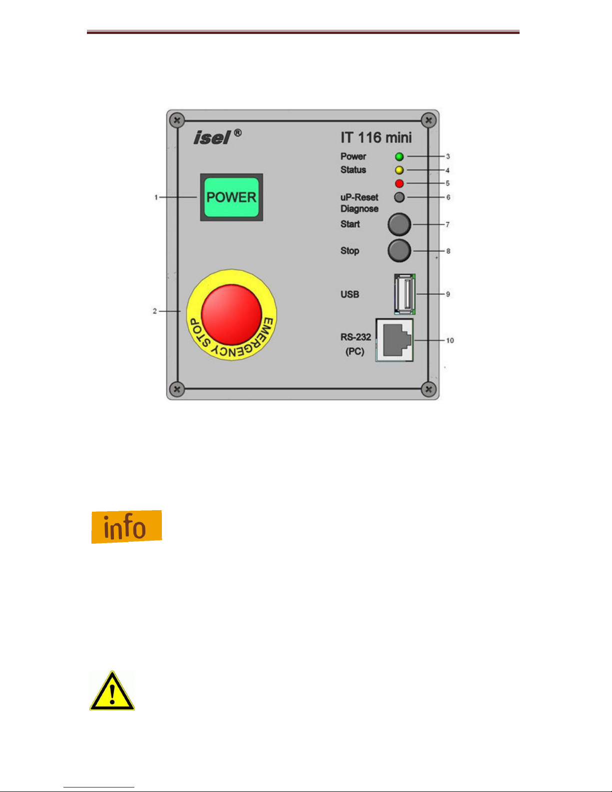
4.1 Front side IT116 mini / IT116 flash
1 - Power-button
Use this button to switch on motor power supply voltage for the motor power
amplifiers.
Conditions for switch on:
- Main power switch on the controller back side is switched on
- Emergency stop button is pulled out
Be sure that the contacts for external emergency stop switch
on the remote connector are bridged!
If power supply voltage is successfully switched on the power button is lighted green.
2 – Emergency stop button
Turns off the power supply for the motor power amplifiers and the working spindle in
case of any danger. This means dangers for the user’s health or machine safety.
If you push the emergency stop switch the motor power supply will
be switched off immediately (stop category 0, EN 60204-1) and any
axes motion will be stopped. The main power supply voltage of
115/230VAC lies still on the device, only the motor power supply
voltage for the amplifiers is switched off.
Page 9

IT116 flash / IT116 mini operating instruction
page - 9
3 - LED – power
This LED signalizes that the net power supply voltage is switched on by the main
switch on the back side of the controller.
4 - LED – diagnosis (future extension)
In case of any fault a blink code will be shown.
5- LED – over temperature
This LED signalizes a over temperature of the motor power amplifier.
LED only available on IT116 mini!
6- Reset button
Use this button to reset the micro processor and the motor power amplifier. All
activities will be interrupted and signal outputs are set to default state. Possible
appeared step losses will be ignored!
7 - Start button
Press this button to execute a stored user program in the flash memory of the
controller.
8 - Stop button
Use this button to stop a running user program / axis motion. Press the start button to
continue the execution of the user program / axis motion.
9 - USB slot (future extension)
This interface is used to connect a USB flash drive download user programs in the
flash memory of the controller.
10 - RS232 programming interface
Communication between IT116 and control PC is realized via a serial interface
(RS232). Use the delivered communication cable for connection. Plug the Sub-D (9pin) connector to a COM port on the PC and the RJ45 connector to the controller front
side socket.
A software protocol realizes the faultless transmission of the ASCII characters.
Therefore it’s necessary that both systems respect the communication protocol:
• The connected control PC sends a command which ends with a line end
character [CR, char(13).
• The processor unit quits the execution or storing of a command with the
quitting signal 0[char(48)] or returns an occurred error with an ASCII character
unequal 0.
Data transfer parameters on IT116 are defined as follows:
• 19200 baud, 8 data bits, 1 stop bit, no parity
Page 10

IT116 flash / IT116 mini operating instruction
page - 10
4.2 Back side IT116 mini / IT116 flash
IT116 flash IT116 mini
Page 11

IT116 flash / IT116 mini operating instruction
page - 11
AC input – main net input module
The net input module consists of net input socket, net filter, fuse holder und net main
switch. Connect the controller via delivered net cable to a free receptacle. After that
you can switch on the controller with the net main switch.
Stepper-motor – connector
Sub-D 9-pin connector for motor module (CNC axis).
Connect / disconnect the Sub-D plug only if controller is switched off.
dieses Ignoring this instruction can lead to damage the motor cable or
stepper motor amplifier.
p
in description
1 motor phase 2B
2 motor phase 2A
3 motor phase 1B
4 motor phase 1A
5 +24VDC
6 brake (+24VDC/1,8A output with reference potential GND)
7 limit switch 2 (Input +24VDC, if limit switch 2 is not actuated: NC
8 GND
9 limit switch 1 (Input +24VDC, if limit switch 1 is not actuated: NC
figure 1– motor module connector 2- phase stepper motor
Page 12

IT116 flash / IT116 mini operating instruction
page - 12
Remote - interface to security circuit
This connector is used to integrate the controller into a higher ranked security circuit
system. Please note that the external power button input is only useable if the power
button in the front side of the controller is switched off. That will be realized by setting
a jumper on the control board. Therefore you have to unscrew to front cover of the
controller (look at figure 3, 4)
pin
description
1 potential free contact (make contact)
2 potential free contact (make contact)
3 external emergency stop (brake contact 1), 11
4 external emergency stop (brake contact 1), 12
5 external emergency stop (brake contact 2), 21
6 external emergency stop (brake contact 2), 22
7 external power (make contact)
8 external power (make contact)
figure 2 – connection for external security circuit
The length of the connection cable for the external emergency
stop button must not more than 5m.
Page 13

IT116 flash / IT116 mini operating instruction
page - 13
figure 3 – IT116 flash, jumper JP4 for power extern / intern
figure 4 – IT116 mini, jumper JP4 for power extern / intern
Page 14

IT116 flash / IT116 mini operating instruction
page - 14
Impulse - interface impulse control
Use this connector to integrate the function keys start button, stop button and reset
from the controller front side as external signal inputs.
pin
description
1 start
2 +24VDC
3 stop
4 +24VDC
5 reset
6 +24VDC
figure 5 – impulse control connection
Input - digital inputs
The controller IT116 flash / IT116 mini has 4 digital user inputs. Use these inputs to
connect external devices like sensors, switches or outputs from other devices. All
inputs are opto-decoupled. If +24VDC lies on the input a logical HIGH is signalized.
Not connected (e.g. switch open) a logical LOW is signalized.
The input current is about 8 mA.
figure 6 – digital inputs wiring
Page 15
IT116 flash / IT116 mini operating instruction
page - 15
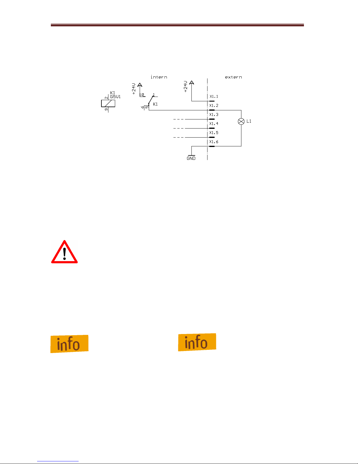
Output - digital outputs
The controller IT116 flash / IT116 mini has 4 digital user outputs. Use these outputs
to connect external devices like relays, or inputs from other devices. The maximum
load of each relay output is 24 VDC/1 A.
figure 7 – digital outputs wiring
4.3 DIP - switch settings
The DIP-switches are used to configure the motor amplifier. Depending on controller
type the DIP switch is based on the top side (IT116 flash) or on the back side (IT116
mini) of the controller.
Configuration of the controller should be done before first startup so
that a connected motor will not be damaged because of an incorrect
power setting.
IT116
flash
IT116
m
ini
DIP switch is based on the
top side of the controller.
DIP switch is based on the
back side of the controller.
1:
current setting 1
2: current setting 2
3: current setting 3
4: current reduction
5: step resolution 1
6: step resolution 2
7: step resolution 3
8: step resolution 4
1:
switch motor brake „manually“
2: current reduction
3: step resolution 1
4: step resolution 2
5: current setting 1
6: current setting 2
Page 16

IT116 flash / IT116 mini operating instruction
page - 16
4.3.1 DIP-switch settings on IT116 flash
current setting (DIP-switch 1, 2, 3)
Use the DIP switches 1, 2 and 3 to set the current of the motor. The following table
shows the motor current (RMS) setting for the different switch positions:
The factory set of the motor current is 2,03 A (RMS)on all motor
power amplifiers.
current reduction (DIP-switch 4)
Use the DIP switch 4 to set the automatic current reduction. If the DIP switch is set to
ON the automatic current reduction is deactivated. DIP switch in state OFF means
that the current is set to 60% of the motor current if the motor standstill.
DIP 4 current reduction in %
ON 0% reduction (deactivated)
OFF 60% reduction
If the holding torque is sufficient, the activated automatic current
reduction is recommended.
Page 17

IT116 flash / IT116 mini operating instruction
page - 17
step resolution (DIP-switch 5, 6, 7, 8)
Use the DIP switches 5, 6, 7 and 8 to set the step resolution. Setting the factor to a
higher value causes a smooth motion of the motor but the maximum reachable
velocity will taking down. Also the motor torque will be reduced to 75% in microstep
mode. The following table shows the DIP switch settings for the different step
resolutions:
micro steps
steps
/
rev. (1,8 °
motor
) SW5
SW6
SW7
SW8
2 400 OFF ON ON ON
4 800 ON OFF ON ON
8 1600 OFF OFF ON ON
16 3200 ON ON OFF ON
32 6400 OFF ON OFF ON
64 12800 ON OFF OFF ON
128 25600 OFF OFF OFF ON
5 1000 ON ON ON OFF
10 2000 OFF ON ON OFF
20 4000 ON OFF ON OFF
25 5000 OFF OFF ON OFF
40 8000 ON ON OFF OFF
50 10000 OFF ON OFF OFF
100 20000 ON OFF OFF OFF
125 25000 OFF OFF OFF OFF
The Factory set of the step resolution is 800 steps/rev for all motor
power amplifiers.
4.3.2 DIP-switch settings on IT116 mini
switch motor brake „manually“ (DIP-switch 1)
Use this function to switch the motor brake manually. It can be necessary if you wish
to move the motor with a hand wheel if main power supply voltage is switched off. In
nromal mode the DIP switch should be set to OFF.
DIP 1 brake
ON output brake is always switched on
OFF output brake will be switched automatically
Page 18

IT116 flash / IT116 mini operating instruction
page - 18
current reduction (DIP-switch 2)
Use the DIP switch 2 to set the automatic current reduction. If the DIP switch is set to
ON the automatic current reduction is deactivated. DIP switch in state OFF means
that the current is set to 50% of the motor current if the motor standstill.
DIP 4 current reduction in %
ON 0% reduction (deactivated)
OFF 50% reduction
If the holding torque is sufficient, the activated automatic
current reduction (DIP2 = OFF) is recommended.
step resolution (DIP-switch 3,4)
Use the DIP switches 3 and 4 to set the step resolution. Setting the factor to a higher
value causes a smooth motion of the motor but the maximum reachable velocity will
taking down. Also the motor torque will be reduced to 75% in microstep mode. The
following table shows the DIP switch settings for the different step resolutions:
micro steps steps/rev
(for 1,8° motor)
max. velocity in kHz DIP 3 DIP 4
1 200 15 KHz ON ON
2 400 7,5 KHz OFF ON
4 800 3,75 KHz ON OFF
8 1600 1,875 KHz OFF OFF
current setting (DIP-switch 5,6)
Use the DIP switches 5 and 6 to set the current for the motor. It is possible to set the
current in four steps:
current in A DIP 5 DIP 6
3,33 A ON ON
2,50 A OFF ON
1,67 A ON OFF
0,67 A OFF OFF
Page 19

IT116 flash / IT116 mini operating instruction
page - 19
5 Electrical connection and initial operation
Preparation
Before first startup of the controller please check the scope of delivery. The following
parts should be included:
- Net power supply cable
- Null modem cable Sub-D 9-pin RJ45
- Package with connectors
- Operating instruction
If all this parts are included you can begin initial operation.
Provide all electrical connections.
Connectors
- Connect Net power supply cable
- Connect axis (motor) with the controller IT116 (back side)
configuration
- Set DIP-switches (see chapter 4.3)
Initial operation
- Switch on controller with main power switch on the back side
- Check if power LED lights
- Check if emergency switch is pulled out
- Push power button on the front of the controller
- If a user program is saved on the controllers flash memory you can press the
start button to execute the program
- If no user program is saved in the flash memory you have to download your
program from PC to controller (future extension – loading a user program from
an USB flash device)
- Now it should be able to start execution of the program by pressing the start
button
- If you have not written a user program you should be write your first user
program with help of the software PALPC 2.1
Page 20

IT116 flash / IT116 mini operating instruction
page - 20
6 PALPC: User programming for CNC mode and download
Creating user programs for 1-axis-controller IT116 flash /IT116 mini is realized with
the software PALPC.exe. The implementation method is simple and described in /3/.
Analyze technological problem definition:
• Layout program algorithm (solve problem definition)
• Implementation of the control algorithm into a PALPC source program *.ppc; edit
code with text editor
• Compile PALPC source file with PALPC compiler; on faultless translation an
output file *.out is created by the compiler
• Download output file *.out into the flash memory of 1-axis-controller MC1
• Start program and check control behavior regarding technological problem
definition
6.1 Install programming software PALPC.exe
To install PALPC software do the following:
1. Insert PALPC 2.1 (Part.-No.: Z11-331810) installation CD in your PCs / Notebooks
CD/DVD drive. The following window will be shown.
Page 21

IT116 flash / IT116 mini operating instruction
page - 21
2. Click on “Install PAL PC” and follow the installation instructions.
If this window is not shown start Windows Explorer and open the
root directory of the CD/DVD drive / installation medium and
double click on file “Autorun.exe”.
PALPC installation assistant installation dialog:
Page 22

IT116 flash / IT116 mini operating instruction
page - 22
3. Start PALPC.exe via start menu entry or desktop shortcut. On first startup an
activation window will be shown. Enter delivered registration data (serial number
and activation code) into the dialogs edit fields.
6.2 User programming for CNC mode and download
The use of PALPC and user programming are described in /3/.
For 1-axis-controller IT116 flash / IT116 mini note following specialties:
Page 23

IT116 flash / IT116 mini operating instruction
page - 23
1. The declaration
#control IT116FLASH;
defines target controller as 1-axis-controller IT116 flash
#control IT116MINI;
defines target controller as 1-axis-controller IT116 mini
2. The declaration
#steps steps_ resolution ;
defines the step resolution set by DIP switch
e.g. #steps 1600; /8 micro steps per full step * 200 full steps/motor revolution
3. The declaration
#elev value_spindle_elevation;
defines the spindle elevation of the connected linear axis,
e.g. #elev 10 /elevation 10mm
#elev 360°/ transmission ratio;
defines the transmission ratio of the connected rotary axis,
e.g. ZR20 with transmission ratio 1:20:
18
20
360
=
°
#elev 18;
Page 24

IT116 flash / IT116 mini operating instruction
7 Declaration of Conformity
Der Hersteller
The manufacturer
isel Germany AG
Bürgermeister-Ebert-Str. 40
D-36124 Eichenzell
erklärt hiermit, dass folgendes Produkt
hereby declares that the following product
Geräteart: 1-Achs-Controller IT116
Device: 1-axis controller IT116
Typ: IT116 flash
Type:
Art.-Nr.: 381016
Product - No.:
mit den Vorschriften folgender Europäischer Richtlinien übereinstimmt:
complies with the requirements of the European Directives:
EG-Richtlinie 2004/108/EG
EC-Directive 2004/108/EC
EMV Richtlinie
EMC directive
EG-Richtlinie 2006/95/EG
EC-Directive 2006/95/EC
Niederspannungsrichtlinie
low voltage directive
Folgende harmonisierte Normen wurden angewandt:
Following harmonized standards have been applied:
EN 61000-6-2:2006 EMV - Fachgrundnorm - Störfestigkeit für Industriebereich
EMC - Generic standards - Immunity for industrial environments
EN 61000-4-2:2009 EMV - Prüf- und Messverfahren - Prüfung der Störfestigkeit gegen Entladung
statischer Elektrizität (ESD)
EMC - Testing and measurement techniques; Electrostatic discharge immunity test
EN 61000-4-4:2013 EMV - Prüf- und Messverfahren - Prüfung der Störfestigkeit gegen schnelle
transiente elektrische Störgrößen (Burst)
EMC - Testing and measurement techniques - Electrical fast transient/burst immunity test
EN 61000-4-5:2013 EMV - Prüf- und Messverfahren - Prüfung der Störfestigkeit gegen
energiereiche Impulse (Surge)
EMC - Testing and measurement techniques - Surge immunity test
EN 61000-4-11:2005 EMV - Prüf- und Messverfahren - Prüfung der Störfestigkeit gegen
Spannungs-einbrüche / Spannungsunterbrechungen
EMC - Testing and measurement techniques - Voltage dips, short interruptions and voltage
variations immunity tests
EN 61000-6-4:2011 EMV - Fachgrundnorm - Störaussendung Industriebereich
EMC - Generic standards - Emission standard for industrial environments
DIN EN 55011:2011 Industrielle, wissenschaftliche und medizinische Hochfrequenzgeräte (ISM-
Geräte) - Funkstörungen - Grenzwerte und Messverfahren
Industrial scientific and medical (ISM) radio-frequency equipment - Electromagnetic
disturbance characteristics - Limits and methods of measurement
EN 60204-1:2006
Sicherheit von Maschinen – Elektrische Ausrüstung von Maschinen –
Teil 1: Allgemeine Anforderungen
Safety of machinery – Electrical equipment of machines – Part 1: General requirements
Dermbach, 09.07.2014
Werner Kister, Vorstand / managing board
Page 25

IT116 flash / IT116 mini operating instruction
8 Bibliography
/1/ PAL-PC 2.0 programming instruction, 06/2004
/2/ MD24 / MD28 Microstepping Driver, Hardware Description, 02/2009
Operating instructions and manuals for download you can find here:
www.isel-data.de/manuals
9 Index
#
#control · 25
#elev · 25
#steps · 25
A
activation code · 24
air circulation · 5
Ambient temperature · 5
C
current reduction · 17
current setting · 17
D
Declaration of Conformity · 27
digital inputs · 7, 15
digital outputs · 7
digital outputs · 16
DIP –switch · 16
F
fuse · 8
I
impulse control · 15
initial operation · 20
Initial operation · 20
installation dialog · 22
intended use · 5
IT116 flash
· 6
IT116 mini
· 6
L
Low voltage directive · 5
M
motor brake · 18
motor connector · 12
O
output file · 21
P
PALPC compiler · 21
PALPC.exe · 21
peak current · 7
power supply · 7
program memory · 7
R
rated current · 7
RS232 programming interface · 10
S
safety class · 7
Scope of delivery · 6
security circuit · 13
serial number · 24
step resolution · 18
Storage temperature · 5
T
text editor · 21
W
weight · 7
 Loading...