

Page 1
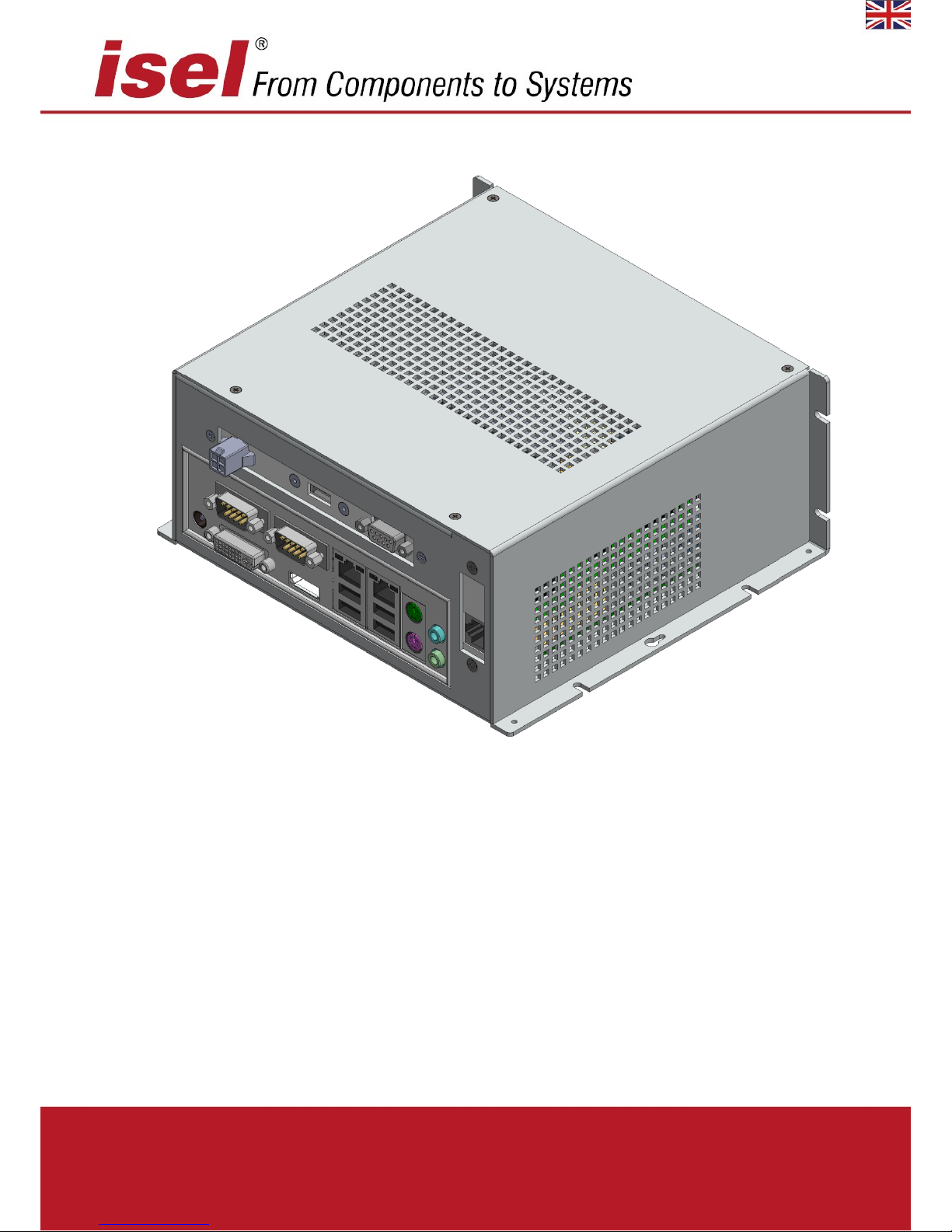
iPC25 - F
Operating instructions
Page 2

iPC25 operating instructions
The information, technical data and measurements contained in this publication are based on the
state of the art at the time of publication. However, any printing errors and errors that may be
present can not be excluded. We would be grateful for any suggested improvements or references
to errors.
It should be noted that the software and hardware names used in our publications are generally
the subject of protection as trademarks, or under proprietary rights, or patent law.
All rights reserved. No part of our publications may be reproduced in any form (print, photocopy or
any other process) without the written permission of isel Germany AG or processed, reproduced or
distributed using electronic systems.
The information contained in this manual is subject to change without notice. The contents are
subject to change without notice.
Manufacturer: isel Germany AG
Bürgermeister-Ebert-Straße 40
D-36124 Eichenzell
Tel.: (06659) 981-0
Fax: (06659) 981-776
E-mail: automation@isel.com
http://www.isel.com
Review index
Date of
change
Reason for change
Changed by
04/05/2015
First edition
RL a 29/05/2017
Supplement D3313-S4
HG
b
17/07/2017
EMC / low voltage directive
RL
Current operating guides for download can be found under:
www.isel.com/en/support-downloads/manuals.html
Page 3

iPC25 operating instructions
Contents
1 General notices ................................................................................................................... 1
1.1 Safety symbols ................................................................................................................. 1
1.2 Safety notices ................................................................................................................... 1
2 Product description ............................................................................................................ 2
2.1 Technical data .................................................................................................................. 2
2.2 Interfaces iPC25 - F ........................................................................................................... 4
3 Assembly and start-up ....................................................................................................... 6
3.1 Installation dimensions ..................................................................................................... 6
3.2 Switching on the control unit ............................................................................................ 7
4 Recovering the operating system Windows® Embedded Standard 7 ............................. 8
5 Maintenance and repair ..................................................................................................... 9
6 EG-Konformitätserklärung ........................................................................................ 10
Page 4
iPC25 operating instructions
Page - 1
1 General notices
Carefully read the operating instructions to the end and follow the instructions given. Failure
to observe these operating instructions can result in property damage, serious personal injury or
death.
1.1 Safety symbols
Attention
This symbol indicates that there is a risk to the life and health of personnel.
Danger
This symbol indicates that there is a risk to the material, machine and the
environment.
Information
This symbol highlights important information.
1.2 Safety notices
▪ The industrial PCs iPC25 are based on the latest state of the art and the
recognised safety regulations.
▪ The device may only be used for its intended use.
▪ The device may only be operated in an impeccable technical condition. Faults
must be removed immediately. Children and unauthorised persons must not
operate the device.
▪ All work must be carried out exclusively by authorised personnel and taking into
account the regulations of the electrical industry and accident prevention
regulations.
▪ Installation and use of the equipment must be carried out according to the
standards of the declaration of conformity. The regulations and limits set by the
manufacturer do not protect the device from improper use of the equipment.
▪ The device must not be exposed to high humidity and high vibrations.
▪ Keep these operating instructions carefully and make sure each user observes
them!
Page 5
iPC25 operating instructions
Page - 2
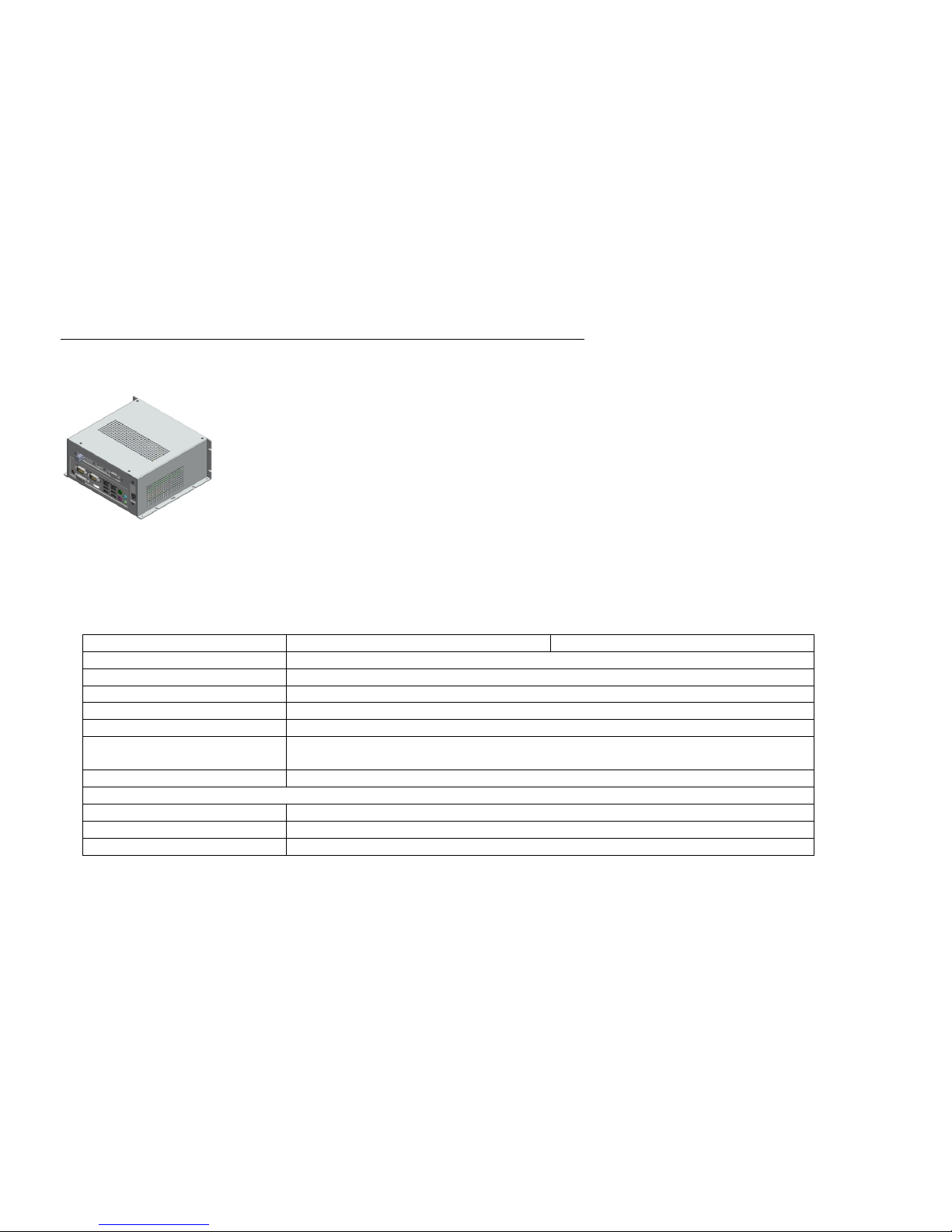
2 Product description
2.1 Technical data
Item number 371066 xxxx
4001 (E)
4001 P (E)
Dimensions (W x H x D):
210 x 90 x 190 mm
Weight:
1.2 kg.
Ambient temperature:
0°C to 35°C
Relative humidity:
max. 90% non condensing
Protection type
IP20
Supply voltage:
on the interface 8 (see 2.2)
12 VDC/min. 100W (external power supply 12V/ 100W required)
Use:
Industrial area / Home- Office area
Form-Factor:
Mini-ITX
CPU:
AMD GX-222GC
Main memory
2xSO DIMM Socket (1.5V/ 1.35V), max. 16GB, SC, DDR-1333/ DD3-1600
Page 6

iPC25 operating instructions
Page - 3
Hard drive:
2,5“ HDD 500GB
2,5“ SSD
256GB MLC/MTPF 2mill. Std.
Operating system:
Windows 7 Embedded standard 64bit
Connections:
external
1 x DVI-I, 1xDisplayPort
1 x PS/2 keyboard, 1 x PS/2 mouse
5 x USB 2.0
2 x LAN 1GBit
2 x serial Port RS 232
1 x Sub-D9-pin connection for iBP10 / iBP17 / iOP-19-TFT
Audio Line in, Line out
12 V,DC power supply
internal
PCI Express x4 Slot
1 x Mini PCI Express Slot x4 (incl. USB2.0)
USB 2.0 / USB 3.0 channels
LVDS Dual Channel / Backlight Inverter
other internal connections, see data sheet Mainboard
Optional connections:
USB
DVI-I/VGA interface / DVI-I/HDMI via Interface-Connector
Page 7

iPC25 operating instructions
Page - 4
2.2 Interfaces iPC25 - F
No.
Interface
1
DVI-I connection, optional adapter DVI-I available on VGA
2
RS 232 connection
Serial interface RS232 –COM1 + COM2
3
LAN connection
2x RJ45 socket for network
4
USB interfaces
4 x USB 2.0 interfaces for the connection of peripherals
5
Mouse, Keyboard Connection
Connection socket for mouse and keyboard
6
Audio connection
Jack socket Line In, Line Out
7
1 x CAN connection
CAN-Bus connection RJ45, optional CAN Duo – 2 x separate CAN-Bus
8
Connection of the power supply for cabinet mounting
with 2-core cable (+ 12VDC white / GND brown)
12 VDC/100W supply voltage
Page 8

iPC25 operating instructions
Page - 5
9
SubD-9-pin socket for connection iBP10 / iBP17 / iOP-19-TFT
only for cabinet mounting
Pin
Description
Description
1
PWR BTN +
Connection for Power key +
2
PWR BTN GND
Connection for Power key GND
3
PWR LED +5VDC
Connection for power indicator LED +
4
PWR LED GND
Connection for power indicator LED GND
5
HDD LED +5VDC
Connection for HDD power indicator LED +
6
+12VDC
Supply voltage for TFT +12V
7
GND
Supply voltage for TFT GND
8
n.v.
9
HDD LED GND
Connection for HDD power indicator LED GND
Power supply for computers and monitors only possible in connection
with a sufficiently dimensioned power supply, with iBP10 / iBP17 /
iOP-19-TFT at least 100W.
10
Multifunction screen for additional optional connections
11
Connector for power supply 2-pin plug when used with external plug-in power
supply 12 VDC/5A hollow plug 5.5/2.5mm (+ pole inside)
Attention: Only one power supply connection is available at all times.
Based on the variants/item numbers
12
Connection for monitors with display port
13
additional USB interface
1 x USB 2.0 interfaces for the connection of peripherals
Page 9

iPC25 operating instructions
Page - 6
3 Assembly and start-up
3.1 Installation dimensions
Make sure that there is always sufficient clearance for the air circulation on the
ventilation slots of the iPC. Failure to observe this measure will result in overheating
and possible defects in the control computer.
Avoid, as far as possible, extreme environmental conditions.
Protect the PC from dust, moisture and heat.
The ventilation slots of the PC must not be covered.
Scale drawing iPC25- F
Page 10

iPC25 operating instructions
Page - 7
3.2 Switching on the control unit
The control unit is switched on via the contacts of the sub-D9-pin socket connection in the slot of
the iPC (see chapter 2.2).
When a 12V DC supply voltage is applied, the computer can also power up the
operating system independently. This is the default setting in the BIOS of the computer.
On delivery, the IPC25 computers are set up, so that the standalone start-up
is disabled.
The BIOS setting can be found under "POWER Power Failure Recovery“
Important notice!
If the start-up of the control computer is set up in the BIOS when the supply voltage is applied, the
computer must be shut down properly before the machine is switched off. Otherwise there is the
risk of a loss of data as well as a damaged, operating system that can no longer be booted.
Page 11

iPC25 operating instructions
Page - 8
4 Recovering the operating system Windows® Embedded Standard 7
Important information
4.1 Preparations for restoring the operating system.
Backing up user data
Preparing USB Boot
1) To restore the Windows® Embedded operating system
Standard 7 of your control computer, you need the USB Recovery Stick supplied. This
data carrier contains an image of the operating system of your installed control
computer in the delivery state.
2) The hard disk of the control computer delivered is set to two partitions
in the factory The primary partition (approx. 40 GB) of the hard disk contains
the operating System Windows® Embedded Standard 7, while the second
partition for user data is available.
3) If you have partitioned the hard disk other than in the delivery state,
this will be returned to the delivery state when restored.
I.e only the partitions described under 2.) are created.
1) Back up your user data from all partitions to an external
data carrier (USB stick, USB HDD).
2) If you have made changes to the control configuration of your software since the
delivery please back up your current control configuration with the CNC
wbBackup wizard. This is located within the CNCworkbench entry in the Start
menu. Also save this backup on the external disk!
The backup must be done on an external data carrier,
since when restoring the operating system all partitions
are formatted and thus all data is lost.
1) After you have backed up all the data, you must use the operating system of the
recovery USB stick supplied. Plug the USB stick into an available USB port on the
computer. Switch on the computer and press the <F12> key at the beginning of
the boot process.
The boot menu of the computer is displayed.
2) Use the <Up / Down arrow keys> to select the USB stick in the list
Confirm your selection with the <ENTER> key.
3) If you have set everything correctly, do not boot the installed
operating system but the operating system on the USB Stick.
Alternatively, you can also use the <Delete> key in the system start to call up
the BIOS of the computer There you have to change the boot sequence and set
the USB Recovery Stick as the first boot medium. After saving the settings, the
operating system is now started on the Recovery Stick.
Page 12

iPC25 operating instructions
Page - 9
4.2 Performing system recovery
5 Maintenance and repair
Maintenance
The industrial PCs of the iPC series are maintenance-free.
Cleaning
Switch off the control computer and the connected components and remove the
power supply.
Use a damp, soft cloth for cleaning. Do not use detergents or abrasive cleaners. Be
careful not to allow moisture to enter the housing through the ventilation slots.
1) After you have set the boot medium or the boot-
sequence, start the computer again.
2) If the USB stick does the booting, a "Blue"
cube is displayed on the screen and below this a rotating circle ".
3) After loading the operating system, a command line starts
and then the Windows® Embedded Standard 7 Recovery Wizard.
4) Follow the wizard's instructions. Click on the last
window on the "Install" button to start the recovery.
After successful recovery, a wizard window is displayed. Confirm with OK!
5) Remove the USB Stick (Recovery Stick).
6) Now in the still open command line window, enter the command
<exit> to close the window. The computer will now start again
Page 13

iPC25 operating instructions
Page - 10
6 EG-Konformitätserklärung
EC - Declaration of Conformity
Der Hersteller
The manufacturer
isel Germany AG
Bürgermeister-Ebert-Str. 40
D-36124 Eichenzell
erklärt hiermit, dass folgendes Produkt
hereby declares that the following product
Geräteart:
Industrie PC
Device: industrial PC
Typ: iPC25-F
Type: iPC25-F
Art.-Nr.: 371066 10xx
Product - No.: 371066 10xx
mit den Vorschriften folgender Europäischer Richtlinien übereinstimmt:
complies with the requirements of the European Directives:
EG-Richtlinie 2014/30/EU
EC-Directive 2014/30/EU
EMV Richtlinie
EMC directive
EG-Richtlinie 2014/35/EU
EC-Directive 2014/35/EU
Niederspannungsrichtlinie
low voltage directive
Folgende harmonisierte Normen wurden angewandt:
Following harmonized standards have been applied:
EN 61000-6-2:2006-
EMV - Fachgrundnorm - Störfestigkeit für Industriebereich
EMC - Generic standards - Immunity for industrial environments
EN 61000-4-2:2008
EMV - Prüf- und Messverfahren - Prüfung der Störfestigkeit gegen Entladung statischer
Elektrizität (ESD)
EMC - Testing and measurement techniques; Electrostatic discharge immunity test
EN 61000-4-4:2012
EMV - Prüf- und Messverfahren - Prüfung der Störfestigkeit gegen schnelle transiente
elektrische Störgrößen (Burst)
EMC - Testing and measurement techniques - Electrical fast transient/burst immunity test
EN 61000-4-5:2007
EMV - Prüf- und Messverfahren - Prüfung der Störfestigkeit gegen energiereiche Impulse
(Surge)
EMC - Testing and measurement techniques - Surge immunity test
EN 61000-4-11:2005
EMV - Prüf- und Messverfahren - Prüfung der Störfestigkeit gegen Spannungs-einbrüche /
Spannungsunterbrechungen
EMC - Testing and measurement techniques - Voltage dips, short interruptions and voltage
variations immunity tests
EN 61000-6-4:2011
EMV - Fachgrundnorm - Störaussendung Industriebereich
EMC - Generic standards - Emission standard for industrial environments
DIN EN 55011:2011
Industrielle, wissenschaftliche und medizinische Hochfrequenzgeräte (ISM-Geräte) Funkstörungen - Grenzwerte und Messverfahren
Industrial scientific and medical (ISM) radio-frequency equipment - Electromagnetic
disturbance characteristics - Limits and methods of measurement
Dermbach, 17.07.2017
Page 14

iPC25 operating instructions
Page - 11
___________________________
Werner Kister, Vorstand / managing board
IMPORTANT NOTICE!
If there are problems with ISEL Germany AG computers,
please always first re-install the operating system with the help of the recovery USBStick supplied and matching the serial number.
The recovery stick contains in the folder „Recovery -> Wimtargetfolder“ a Windows
image with the extension xxxx.wim (approx. 3 GB).
This can be re-installed using the operating instructions of the computer.
If this is not the case, please send this recovery stick back to us and we will install
the Windows image on your stick. This means that you can reset your computer to
the delivery status at any time.
This will save you time and money.
IMPORTANT!
For repairs to computers,
always include the recovery stick that matches the serial number.
When returning a computer,
make sure you return the accessories supplied.
Accessories in the accessory box with attached serial number consist of:
•
USB recovery stick (matching the computer / licence number)
•
DVD driver of the main board
•
Manuals for the main board
•
Computer’s voltage supply cable
Page 15

 Loading...